Viessmann norpe SPIRIT User manual

SPIRIT – E-NOVUS – E-VENTUS – E-VISIO
INSPI– INTRO – LUXO – NARDO – MAXIM
ICONIC – GUSTO– SOFIE – EMILIE – VERA
05/2015Please keep these instructions for future reference!
UserGuide
EN FI SV NO DA EE RU LV

SV
MD
RI
1

2

A 920 930 30
230 650 1880
M
230 v 1 50 Hz Class
No 244352 Control M
Porvoo Finland
norpe
KR-
Type
cc
Electric
diagram
3

Light
switch
4
4

5
5

ENGLISH
1. Introduction ..................................................................................................................................... 2
1.1. Before you start ................................................................................................................... 2
1.2. Warranty ............................................................................................................................... 2
1.3. Restrictions .......................................................................................................................... 2
1.4. Spirit, e-Novus, e-Ventus and e-Visio MD, Intro RI and Inspi SV ..................................... 3
1.5. Maxim CI/FI .......................................................................................................................... 3
1.6. Luxo FGD ............................................................................................................................. 3
1.7. Nardo HGD ........................................................................................................................... 3
1.8. Iconic FSV ............................................................................................................................ 3
1.9. Gusto SO .............................................................................................................................. 4
1.10. Sofie SO ............................................................................................................................. 5
1.11. Emilie SO ............................................................................................................................ 5
1.12. Vera SO ............................................................................................................................... 6
1.13. Night covers, glass lids and doors .................................................................................. 7
2. Preparations .................................................................................................................................... 7
2.1. Package ................................................................................................................................ 7
2.2. Transport damage ................................................................................................................ 8
2.3. Installation ........................................................................................................................... 8
2.4. Cleaning before use ............................................................................................................ 8
2.5. Electrical connections ........................................................................................................ 8
3. Operation ......................................................................................................................................... 9
3.1. Start-up ................................................................................................................................ 9
3.2. Operating thermostat .......................................................................................................... 9
3.2.1.EliwellID971.............................................................................................................. 9
3.3. Automatic defrosting ........................................................................................................ 11
3.4. Loading cabinet ................................................................................................................. 11
3.5. Fan speed control .............................................................................................................. 12
4. Maintenance .................................................................................................................................. 13
4.1. Cleaning ............................................................................................................................. 13
4.2. Troubleshooting ................................................................................................................. 14
4.3. Interruption in mains supply ............................................................................................ 14
4.4. Servicing and spare parts ................................................................................................ 14
4.5. Disposal of equipment ...................................................................................................... 14
iVersion05/2015
ENGLISH
SM

1. Introduction
1.1. Before you start
Read these instructions carefully. They explain how to install, place, use and service the cabinet
correctly and safely.
Keep these instructions in a safe place and available for other users.
The cabinet must be installed and started up in compliance with the manufacturer's instructions
and in conformance with local instructions and regulations.
If a defect occurs in the cabinet or cabinet equipment, or the cabinet does not operate normally,
check that this does not create a hazard to people or property. If necessary, disconnect the
cabinet and contact the nearest service organisation. All users of the cabinet must be aware of
how to use the cabinet correctly and safely.
1.2. Warranty
Each cabinet has a two (2) year durability and material warranty for normal ambient conditions.
Normal ambient conditions must not exceed:
• Relative humidity 60 % RH
• Ambient temperature +25 °C
• Frontal airflow < 0.2 m/s
The warranty does not extend to any breakage of glass, accidental or otherwise.NOTE
1.3. Restrictions
Using the cabinet in any way other than specified in these instructions is prohibited. Only products
that are specified in these instructions or in the brochure for the cabinet may be stored in the
cabinet.
The manufacturer accepts no liability for incidents that are caused by using the cabinet in
contravention of these instructions, or with disregard for the warnings in these instructions or
without following these instructions.
Cabinet is for indoor use only.NOTE
Storing flammable or hazardous liquids in the cabinet is strictly prohibited.NOTE
Climbing inside or on the top of the cabinet is prohibited. Standing on any part of the
cabinet is prohibited.
NOTE
RI cabinet's front panel must be lifted using both hands.NOTE
2Version05/2015
ENGLISH
SM

Cabinets equipped with glass lids and doors: to avoid finger or other injuries handle
with care.
WARNING
1.4. Spirit, e-Novus, e-Ventus and e-Visio MD, Intro RI and Inspi SV
Spirit, e-Novus, e-Ventus and e-Visio MD, Intro RI and Inspi SV display cabinets are intended
for dairy products, processed meat products, convenience foods, salads, processed and
semi-processed foods, drinks, packed meat, fruit and vegetables. The storage temperature ranges
for products are 0...+2° C, +2...+4° C, +4...+8° C, +8...+12° C.
Make sure that the cabinet version and the storage temperature are correct for the product to be
stored.
1.5. Maxim CI/FI
Maxim fridge and freezer cabinets are intended for storing and displaying dairy products, packaged
meat, packed ice creams and frozen foods. The storage temperature ranges for products are
+2...+4° C in fridge cabinet and -23...-21° C in freezer cabinet.
Make sure that the cabinet version and storage temperature are correct for the products to be
stored.
1.6. Luxo FGD
Luxo FGD fridge and freezer cabinets are intended for storing and displaying drinks, ice creams
and frozen foods. The storage temperature ranges for products are +2..+4° C in fridge cabinet
(FGD FC) and -25..-23° C in freezer cabinet (FGD FF).
Make sure that the cabinet version and storage temperature are correct for the products to be
stored.
1.7. Nardo HGD
Modular Nardo HGD fridge and freezer cabinets are intended for storing and displaying ice
creams, frozen foods and convenience foods. The storage temperature ranges for products are
+2...+4° C in fridge cabinets and -23..-21° C in freezer cabinets.
Make sure that the cabinet version and storage temperature are correct for the products to be
stored.
1.8. Iconic FSV
Iconic FSV freezer cabinets are intended for storing and displaying ice creams and other frozen
goods. The storage temperature range is -25..-23° C.
Make sure that the cabinet version and storage temperature are correct for the products to be
stored.
3Version05/2015
ENGLISH
SM

When opening Iconic cabinet doors, note that the opening mechanism is lightened and
the doors open slightly upwards. When the door is opened, the lower corner of the door
ends up further out than it would if the door was in a normal, upright position. This may
result to an unexpected collision. Respectively, the door shuts down softly and slowly.
Do not force or slam the door - instead, let the door close by gravitational force.
Open and close the doors carefully to avoid accidents.
Instruct the customers in the safe use of the doors.
Do not attach any material, for example price tags, on the doors.
WARNING
1.9. Gusto SO
Gusto SO serve over and self-service display cabinets are intended for storing and displaying a
wide variety of foods and foodstuffs, including dairy products, processed meat, convenience
foods, salads, processed and semi-processed foods and packed meat. Gusto SO display cabinets
are available for the deep-frozen, refrigerated and warmed products.
Gusto SO display cabinets are supplied for a number of different storage temperature ranges.
The cabinet versions are:
• Cabinet without integrated machinery unit, 0 version, cooling provided by remote refrigeration
equipment.
• Cabinet with integrated machinery unit, M version, provided with local cooling equipment.
•Freezer cabinet, F.
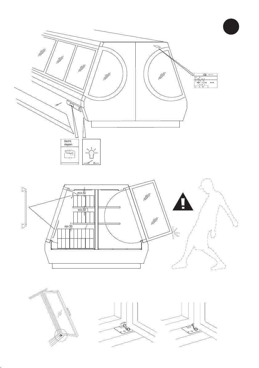
The temperature range in the cabinet is -21..-18° C. The electronic thermostat and light
switch are located in the lower right corner of the cabinet on the service side. The fan
evaporator is located inside the cabinet under the service access covers.
•Heated display counter, H.
The heating equipment for the display counter is comprised of two heating units:
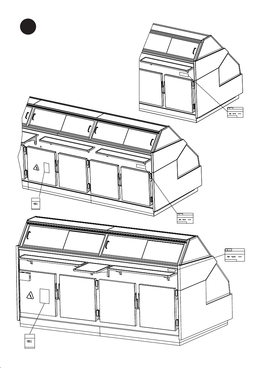
• A heat radiator located in the roof compartment of the cabinet. This radiator is always
switched on when the electric plug is in the wall socket and the main switch (see figure
page 3, figure B2) is turned on. No automated feature disconnects this heating, which
also provides lighting for the cabinet.
• Heating resistors are installed in the base of the storage compartment. Gusto H display
counter has five or seven resistors. The heat output of these resistors is controlled by
a thermostat (see figure page 3, figure C2). The thermostat can be set to the temperature
desired, which is generally +70° C. The maximum setting is +90° C.
The interior surfaces of the cabinet and the lighting/heat radiator shade are
extremely hot. Wear protective gloves.
NOTE
Lift the front glass using both hands. Bring the glass gently to top positionNOTE
Do not push the glass up with force or slam the glass down.WARNING
Make sure that the cabinet version and storage temperature are correct for the products to be
stored.
4Version05/2015
ENGLISH
SM

1.10. Sofie SO
Sofie SO double decker (DD) display cabinets models are intended for storing and displaying a
wide variety of foods and foodstuffs, including cheeses, meat, convenience foods, salads,
processed and semi-processed foods and packed meat.
Sofie SO DD display cabinets are available for both fresh and packed products and are supplied
for a number of different storage temperature ranges. The cabinet versions are:
• Cabinet without integrated machinery unit, 0 version, cooling provided by remote refrigeration
equipment.
• Cabinet with separate refrigeration for upper and lower decks so that they can be switched
off or on separately.
NOTE • When opening the front glass, be sure to hold it with both hands. Move the glass
carefully to lowered position.
• Remember to switch off and empty the upper deck cabinet for the night.
• Remember to clean the drip pan carefully once a week. The drip pan is located
under the evaporator on the upper deck.
• Clean the visible surfaces daily.
Use only Norpe ice chip or meat shelves. Norpe does not guarantee cabinet functionality unless
the manufacturer’s own accessories are used.
The cabinet contains automatic defrosting system. In addition to this, the cabinet must be manually
defrosted at least twice a year or even more frequently, depending on the operating conditions.
Do not push the glass up by force or slam the glass down.WARNING
Make sure that the cabinet version and storage temperature are correct for the products to be
stored.
1.11. Emilie SO
Emilie SO double decker (DD) display cabinets models are intended for storing and displaying
a wide variety of foods and foodstuffs, including cheeses, meat, convenience foods, salads,
processed and semi-processed foods and packed meat.
Emilie SO DD display cabinets are available for both fresh and packed products and are supplied
for a number of different storage temperature ranges. The cabinet versions are:
• Cabinet without integrated machinery unit, 0 version, cooling provided by remote refrigeration
equipment.
• Cabinet with separate refrigeration for upper and lower decks so that they can be switched
off or on separately.
• Upper deck can be switched to self-service cabinet. To do this, move the upper deck glass
to its back position.
5Version05/2015
ENGLISH
SM

NOTE • When opening the upper deck glass, be sure to hold it with both hands. Move the
glass carefully to back position.
• Remember to switch off and empty the upper deck cabinet for the night.
• Remember to clean the drip pan carefully once a week. The drip pan is located
under the evaporator on the upper deck.
• Clean the visible surfaces daily.
Use only Norpe ice chip or meat shelves. Norpe does not guarantee cabinet functionality unless
the manufacturer’s own accessories are used.
The cabinet contains automatic defrosting system. In addition to this, the cabinet must be manually
defrosted at least twice a year or even more frequently, depending on the operating conditions.
Do not push the glass up by force or slam the glass down.WARNING
Make sure that the cabinet version and storage temperature are correct for the products to be
stored.
1.12. Vera SO
Vera SO triple decker (TD) display cabinets models are intended for storing and displaying a
wide variety of foods and foodstuffs, including cheeses, meat, convenience foods, salads,
processed and semi-processed foods and packed meat.
Vera SO cabinet is available for both fresh and packed products and are supplied for a number
of different storage temperature ranges. The cabinet versions are:
•Cabinet without integrated machinery unit, 0 version, cooling provided by remote refrigeration
equipment.
•Cabinet with separate refrigeration for decks so that they can be switched off or on separately
(also the lights).
The lower deck's back storage is cooled using lower deck's front steamer, so it cannot be
used separately.
NOTE • When opening the front glass, be sure to hold it with both hands. Move the glass
carefully to up position.
• The sliding glass doors must be always be closed after use to maintain the correct
cabinet temperature.
• Remember to switch off and empty the upper deck cabinet for the night.
• Remember to clean the drip pan carefully once a week. The drip pan is located
under the evaporator on the upper deck.
• Clean the visible surfaces daily.
• The upper deck fan can be turned off for cleaning.
• If your Vera cabinet is equipped with an optional humidifier system, please follow
the system manufacturer's separate instructions for use and maintenance.
Use only Norpe ice chip or meat shelves. Norpe does not guarantee cabinet functionality unless
the manufacturer’s own accessories are used.
6Version05/2015
ENGLISH
SM

The cabinet contains automatic defrosting system. In addition to this, the cabinet must be manually
defrosted at least twice a year or even more frequently, depending on the operating conditions.
Do not push the glass up by force or slam the glass down.WARNING
Make sure that the cabinet version and storage temperature are correct for the products to be
stored.
1.13. Night covers, glass lids and doors
Spirit, e-Ventus, e-Novus MD, Inspi SV, Intro RI, Maxim, Sofie SO and Emilie SO display cabinets
are optionally supplied with covers, glass lids or doors depending on the type of cabinet.
• Alwayshandlethenightcoverscarefully.
• Donotallowcoverstowindinunderuncontrolledspringforce('whiplash').
• Alwayskeepholdofthehandleofthecoverwhenopeningorclosingittoavoiddamageto
thespringorcovermechanisms.
When opening or closing Maxim night cover, keep the cover horizontal at a
90-degree angle to the cover holder. If the cover is moved at the wrong angle, the
fasteners or the cover holder may fray the edges of the cover.
NOTE
Spirit, e-Ventus, e-Novus MD and Intro RI cabinets can be supplied with either a manually operated
or a motorised cover. For Maxim cabinets only the manually operated option is available.
Motorised night covers are operated manually with the light switch on the right-hand cabinet.
When the lights of the cabinets are switched off from left to right, the night cover is lowered when
the light of the last cabinet is extinguished. Conversely, the lights are switched on by proceeding
from right to left. One motorised unit may control a maximum of four extension covers.
The upper and lower limits of the night cover can be adjusted with the adjusting crank on the
motor for the cover. Remote control for all the lights and motorised night covers in a single store
is also available.
Check regularly that the night cover operates correctly. If the cover needs to be adjusted, contact
your nearest servicing organization.
Glass lids and doors should be opened and closed cautiously to avoid injuries. Instruct
customers how to use them safely.
NOTE
2. Preparations
2.1. Package
Transport or move the cabinet to its destination site in the original factory packing, whenever
possible. The packaging materials are recyclable.
7Version05/2015
ENGLISH
SM

2.2. Transport damage
Unpack the cabinet and check for any sign of damage during transport. Report any damage
immediately to your insurance company, or to the supplier or manufacturer of the cabinet.
2.3. Installation
When installing the cabinet, make sure of the following:
• The area where the cabinet is placed is flat and level.
• The cabinet is not placed in the immediate vicinity of a heat source such as a radiator, warm
air blowing heater or spotlight.
• The cabinet is not exposed to direct sunlight. If necessary, use blinds in any nearby window.
•The cabinet is not placed in the proximity of air conditioning equipment or the main entrance
to the premises.
Strong draught can raise the temperature in the cabinet by several degrees.
Correct positioning of the cabinet optimises temperature conditions and performance.
A heated display counter is always supplied with its own end facings because of its high
temperature. Two end facings are always recommended between cooled and heated
display units. However, two heated display counters can be connected to each other
without end facings.
NOTE
2.4. Cleaning before use
1. Cleanthecabinetsurfacesandthestoragecompartmentforfoodstuffswithamildliquid
detergentbeforeusingthecabinet.
Follow the instructions provided with the detergent.
Make sure that all cleaning fluids are classed as non-toxic and pH 6-8. Do not use
solvent-based detergents.
NOTE
2. Drythesurfacescarefully.
2.5. Electrical connections
The symbol marked on the cabinet (a lightning bolt inside a triangle) indicates that there
are components and wires under the cover containing live voltage. Only personnel
qualified to install and service electrical equipment are permitted access to areas that
contain live voltage.
NOTE
Cabinets without an integrated machinery unit are wired to the electricity supply network by
means of a permanent connection.
Cabinets with an integrated machinery unit operate on single-phase AC current at 230 V/50 Hz
voltage. The electrical socket must be earthed and the circuit must be provided with either a 10
A slow fuse or a 16 A slow fuse. Check the rating plate (see figure page 3, figure A1/A2) to
determine which fuse size applies. Other equipment must not be connected to the same fuse.
8Version05/2015
ENGLISH
SM

The electrical connections for the cabinet are shown in the wiring diagram in the plastic wallet
attached to the side of the electrical terminal box. Always replace the wiring diagram after use.
For more information on the location of the rating plates and wiring diagrams, see figure pages
1-5 in the beginning of this manual.
All electrical connections must be carried out by approved and qualified personnel and
comply with all IEE and local regulations, failure to do this could result in personal or
fatal injury.
WARNING
3. Operation
3.1. Start-up
Display cabinets are designed for remote installation. The company that installs the
cabinet/refrigeration equipment must provide adequate training and instructions on the operation
and location of power supply and service switches needed when carrying out normal cleaning.
The expansion valves in the cabinets must be set to the correct value before starting up the
cabinets. The set values for the thermostats in the cabinets should be checked with a separate
and accurate thermometer.
For cabinets with an integrated machinery unit, the cooling equipment - compressor,
condenser and electrical equipment - is located in the machinery compartment on the
right-hand side of the cabinet as viewed from the service side. The cooling equipment
starts when the electrical plug is inserted into the wall socket.
NOTE
3.2. Operating thermostat
The interior temperatures of the cabinets are controlled by thermostats. During the cooling phase,
the thermostat opens the magnetic valve in the coolant line.
For cabinets with an integrated machinery unit, the thermostat (see figure page 3, figures
B1-E1) switches on the compressor in the machinery compartment.
NOTE
The operating thermostat of the cabinet is set when the cabinet is started up. The setting takes
into account both the temperature required by the products to be displayed and the operating
temperature of the cabinet. Setting the thermostat to a lower temperature may freeze and stop
the evaporator.
The temperature in the cabinet should be checked at regular intervals.
The operating thermostat is set with factory settings. For the operating thermostat instructions,
see the thermostat's own user manual. In case of problems, contact your service company.
3.2.1. Eliwell ID 971
Eliwell ID 971 is a cabinet controller that automates cabinet defrosting by
means of a thermostat and temperature sensor.
3.2.1.1. Keys and menus
The instrument is programmed and controlled with four keys:
9Version05/2015
ENGLISH
SM

•UP arrow-scrollsthroughmenuitems,increasesvalues,activatesmanualdefrosting
function.
•DOWN arrow-scrollsthroughmenuitems,decreasesvalues,programmablebyparameter.
•FNC key-exitfunction,programmablebyparameter.
•SET key-accessessetpointsandmenus,confirmscommands,displaysalarms.
At start-up the instrument performs a lamp test - for a few seconds the display and the LEDs
blink to verify their integrity and correct operation.
The cabinet controller is pre-programmed at the factory. Do not adjust the set values.
Adjusting the thermostat or defrosting values may cause the evaporator to freeze. In
case of problems, please contact your nearest servicing organisation or dealer.
NOTE
The instrument has two main menus: the Machine Status menu and the Programming menu.
3.2.1.2. Machine Status menu
1. PressSETquicklytoaccesstheMachineStatusmenu.Ifalarmsarenotpresent,thelabel
"SEt"appears.
2. ScrollthroughtheotherfoldersinthemenuwithUPorDOWN.
Folders: Pb1 (probe 1 value folder), Pb2 (probe 2 value folder), SEt (setpoint setting folder).
Adjusting the temperature
a. Press SET quickly to access the Machine Status menu. The label of the "SEt" folder
appears.
b. Press SET again to display the Setpoint value. The value appears on the display.
c. Change the Setpoint value with UP or DOWN within 15 seconds.
Displaying probes
When the appropriate label appears, press SET to display the probe value associated to it.
3.2.1.3. Programming menu
1. PressSETformorethan5secondstoentertheProgrammingmenu.
2. ScrollthroughthefolderswithUPorDOWN.
3. PressSETtoenterthedesiredfolder. Thelabelofthefirstvisibleparameterappears.
4. ScrollthroughtheotherparameterswithUPorDOWN.
5. PressSETquicklytoselectthedesiredparameter.
6. SetthedesiredvaluewithUPorDOWN.
7. PressSETtoconfirmtheselectionandmovetothenextparameter.
If you do not press any of the keys for 15 seconds or press FNC to exit the function,
the last value on the display is verified and you return to the previous display.
NOTE
Factory settings
The parameter settings are pre-adjusted at the factory. The settings should not be changed
unless necessary.
3.2.1.4. Manual activation of defrosting cycle
Press UP for 5 seconds to manually activate the defrosting cycle.
10Version05/2015
ENGLISH
SM

If defrosting conditions are not present (for example the evaporator probe temperature is higher
than the defrost stop temperature), the display will blink three (3) times to indicate that the
operation will not be performed.
Diagnostics
The alarm condition is always signaled by the buzzer (if present) and by the LED of the alarm
icon.
• The alarm signal produced by a faulty thermostat probe (probe 1) is shown as E1 on the
instrument display.
• The alarm signal produced by a faulty evaporator probe (probe 2) is shown as E2 on the
instrument display.
3.2.1.5. LED
StatusRelated
function
Position
ONwhenthecompressorisstartedup;blinkingincaseofdelay,
protectionorblockedenabling.
Compressor
orrelay1
ONwhendefrosting;blinkingincaseofmanualenabling.Defrost
ONwhenthealarmisenabled;blinkingwhenthealarmissilenced.Alarm
3.3. Automatic defrosting
Defrosting is controlled by a separate defrosting timer containing a limiter thermostat. Defrosting
lasts approximately 30 minutes and normally takes place automatically 1-4 times a day, depending
on the cabinet model. The temperature inside the cabinet rises by a few degrees during defrosting
and the evaporation fans stop.
Gusto SO cabinet does not need to be defrosted, if it is emptied and turned off for the
night.
NOTE
The drain water from defrosting travels through a pipe to the sewage drain or is transferred to
the sewage drain by a separate pump. Although defrosting is automatic, the cabinet can also be
manually set to defrost. Contact your nearest servicing organisation if you need assistance with
defrosting and cleaning.
Cabinets with an integrated machinery unit have a separate evaporation sump for drain
water, which needs manual emptying. Gusto SO freezer cabinet F always requires a
cabinet-specific sewerage point for the drain water, since there is no condensate
evaporator pan. Because the cabinet’s sewerage point is on a different level than in the
regular Gusto SO model, common drain water line cannot be used.
NOTE
3.4. Loading cabinet
When loading the cabinet, care must be taken that the airflow is retained. Observe the loading
limits of the cabinet. Overloading or improper loading of the cabinet will disrupt the airflow and
raise the temperature of products in the cabinet.
For Luxo FGD and Nardo HGD cabinets, the door of the cabinet can be locked with a locking
latch in open position during loading. Avoid keeping the door open for long periods of time.
11Version05/2015
ENGLISH
SM

For Sofie SO DD and Emilie SO DD cabinets, make sure that the products on display on the
upper deck do not block the air duct on the front side of the cabinet. Do not place products outside
the designated area on the product shelf. For more information, please see the images below.
When loading the cabinet:
• Position the products carefully
• Use the compartment dividers to allow cold air to pass between the
products more easily.
• Use the appropriate product display shelves for different products.
• Leave at least 50 mm of free space between products and the inside
roof surface of the cabinet.
• Do not place products above the loading limit. For more information,
see figure pages 1 and 2 in the beginning of this manual.
• Do not place products so that they protrude over the front edges of
the shelves.
• Do not exceed the maximum load on a shelf, 100 kg per metre.
• Do not place products on the roof of the cabinet.
• Do not stand on the glass edge.
The cabinet is not designed to cool down or warm up products but to maintain them at
the temperature at which they are placed in the cabinet. Food products cooler or warmer
(depending on the cabinet type) than the specified temperature should not be placed
in the cabinet.
NOTE
Load and weight limits must not be exceeded. Objects falling or hurling down may cause
danger to users.
WARNING
3.5. Fan speed control
Emilie and Sofie SO cabinets are equipped with the possibility to control the fan speed. On these
cabinets there are two dials as shown in the picture below. The left hand side dial switch with
two positions and the right hand side potentiometer. When set to “Fixed”, the fan operates at
maximum speed, with the potentiometer located on its right being unavailable. When the the left
hand side switch is set to “Adjust”, the fan speed can be controlled with the potentiometer. The
suitable speed is dependent on ambient conditions, but as a general rule it is the most efficient
to set the potentiometer to the marked “Opt” position.
12Version05/2015
ENGLISH
SM

4. Maintenance
4.1. Cleaning
The following cleaning procedure must be carried out at least twice a year. If products stored in
the cabinet break or leak liquid into the cabinet, the cabinet should be cleaned without delay.
Serve over cabinet should be cleaned daily.
The cabinet must not be cleaned while the fans are running. To disable the fans,
disconnect the cabinet from the electricity supply during cleaning.
NOTE
Evaporators, condensers and parts made of stainless steel may have sharp edges.
Wear protective gloves and work cautiously to avoid cut injuries.
WARNING
1. Disconnectthecabinetfromthemainssupplyorturntheseparateswitchtothecleaning
position.
For Luxo FGD and Nardo HGD cabinets, the door of the cabinet can be locked with a locking
latch in open position during cleaning.
2. Emptythecabinet.
3. Allowthecabinettoreachtheambienttemperature.
4. Removeanydebris.
Do not use picks or sharp tools to remove ice from the evaporator. Damage to the coil may
lead to refrigerant leakage.
To make the cleaning faster, the suction grid can be lifted up easily in Spirit MD, Intro RI
and Inspi SV. For more information on the location of the suction grids, see figure page 1
in the beginning of this manual.
5. Inspectfordrainwaterandremoveit,ifthereisany.
6. Cleantheinteriorsurfacesofthecabinetwithamildliquiddetergent(non-toxic,pH6-8)and
drythesurfacescarefullyusingacleantowel.
7. Whencleaningiscompleted,startupthecabinet.
For cabinets with an integrated machinery unit, check at least once a month that
the condenser is clean. If necessary, vacuum clean the condenser fins and check
that the spaces between the fins are unobstructed. The front panel must be opened
for servicing and maintenance.
NOTE
For Gusto SO heated display cabinet H, the tray located in the centre of the cabinet
on the service side (see figure page 3, figure D2) must be emptied and cleaned
daily. The draught of the tray is c. 5 L ( approx. 2 cm water on the bottom).
NOTE
In the event of a refrigerant leakage all products displayed in the cabinet must be
disposed of and then the cabinet must be cleaned.
NOTE
13Version05/2015
ENGLISH
SM

4.2. Troubleshooting
If a defect occurs in the cabinet or cabinet equipment, or the cabinet does not operate normally,
check that this does not create a hazard to people or property. If necessary, disconnect the
cabinet and contact your nearest service organisation.
4.3. Interruption in mains supply
After a power cut, check that the cabinet operates normally. If necessary, contact your nearest
service organisation.
4.4. Servicing and spare parts
The specifications of the cabinet are marked on the rating plate, which is fixed to the side of the
electrical terminal box in chest cabinets and to the top lighting enclosure on the top front facing
board in upright cabinets. Please inform the authorised servicing organisation of the cabinet type,
cabinet name, cabinet serial number and the Control markings marked on the rating plate.
Only authorised fitters may carry out servicing and repair of the machinery and electrical equipment
in the cabinet.
Use only the original fittings supplied with the cabinet and the manufacturer's accessories for the
specific cabinet. For further information about fittings and accessories, please contact the supplier
of the cabinet.
Lock-up main power switch is located in the power-pack machinery room.NOTE
Fans must be switched of during service action.NOTE
4.5. Disposal of equipment
After reaching the end of its service life, the cabinet must be disposed of in compliance with local
regulations and instructions. Seek expert advice when disposing of substances that are harmful
to the environment and when utilising recyclable material.
14Version05/2015
ENGLISH
SM
This manual suits for next models
13
Table of contents
Languages:
Other Viessmann Merchandiser manuals
Popular Merchandiser manuals by other brands

Dixie Narco
Dixie Narco P Series Technical manual

Hussmann
Hussmann IMPACT D5R datasheet

Kysor/Warren
Kysor/Warren GranBering KW TECHNICAL MANUAL & USER INSTRUCTIONS

Hussmann
Hussmann P4NX-E Technical data sheet

Hussmann
Hussmann Impact Excel P1X-E Technical data sheet

Vollrath
Vollrath T 43R Operating and safety instructions