C. Checking hydraulic fittings at installation site
Tap water pressure
In order for the water softener to
function properly the pressure in the
water supply network must not be
lower than 1.4 bar and higher than 8.0
bars. If water pressure is below the
minimum, pressure raising pressure
tank must be used; if water pressure
exceeds the maximum value,
pressure regulator (pressure reducing
valve) must be installed.
Important notice!
If during daytime water pressure is
high, it is very likely that during night
time it will exceed the maximum value
of 8.0 bars. In this case, we
recommend to install a pressure
regulator. It is recommended to fit
pressure gauges on the installation, in
accordance with the schematic
diagram (figure 2), in order to control
operating water pressure in the
installation.
Water flow rate
In order for the water softener to
function properly the minimum water
flow rate at the water inlet should be
11.0 litres per minute.
D. Selecting installation site for the device
The water softener should be
located as close as possible to
hydrophore (in case of supplying
water from private well [intake]) or
water meter measuring the whole
water in the household (in case of
supplying the household with tap
water). The device should be
located in the immediate vicinity of
the outlet drain.
When installing the device
upstream from the water heater (or
boiler unit), make sure that the
temperature of water at the
connection point does not exceed
490C. It is recommended that a
check valve is fitted between the
water softener and the water heater
(or boiler unit) in order to prevent
hot water backflow to the water
softener. Excessively hot water may
cause damage of control valve
elements as well as the ion
exchange resin.
Make sure that the valve for water
used outside of the house (such as
water used for garden watering) is
installed upstream from the water
softener. Softening of water used
outside of the house is not cost
effective (unless necessary).
Installation site of the water softener
must not be exposed to freezing. If
frozen, the water softener will be
damaged. Any damage resulting
from freezing is not covered by the
warranty.
The water softener is powered with
28 V. The transformer and power
cable are provided along with the
device. Earthed power socket for
the water softener should be
located within the immediate vicinity
of the device and should be
protected against rain and sub-zero
temperatures. The water must be
always connected to the power
supply source; the power socket
must not be fitted with a controller
that could be incidentally switched
off.
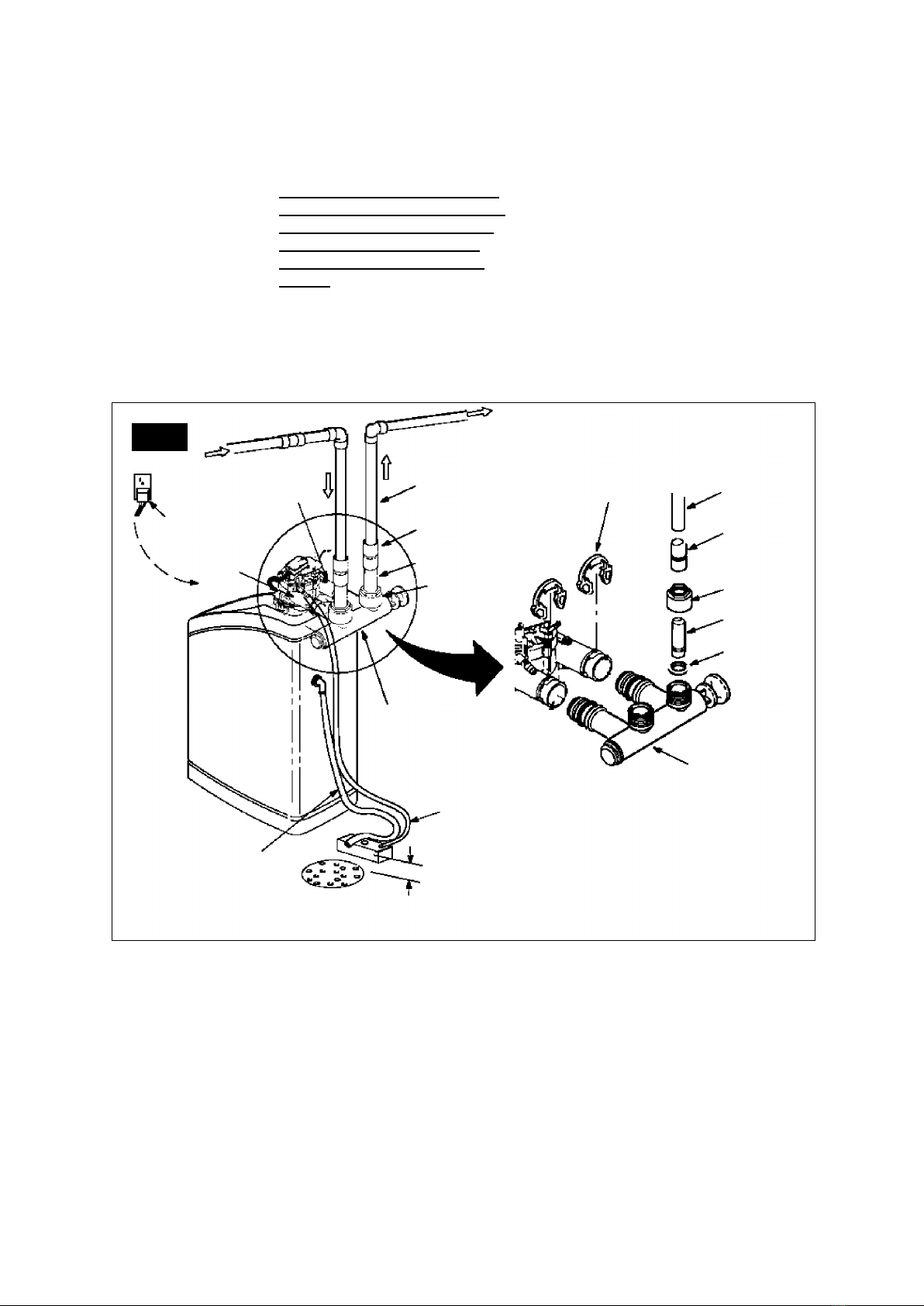
E. Materials
Before commencing installation of the device, it is
important to check relevant connection of inflow
and outflow of water to and from the water
softener. The water “inflow” connection is located
on the right side of the device and water “outflow”
connection on its left side, when facing the device
(fig. 3).