Viewpro DDL24E-ESPB User manual

Video and Data Transmitter
DDL24E-ESPB

Content
1. Package Contents...................................................................................... 1
2. Product Description.................................................................................... 4
2.1. Parameters...................................................................................... 4
2.2. Air Unit Interfaces........................................................................... 4
2.3. Ground Unit Interfaces...................................................................6
3. Installation....................................................................................................8
3.1. Air Unit Installation..........................................................................8
3.1.1. Antenna installation............................................................8
3.1.2. Power supply.....................................................................10
3.1.3. Connection to camera......................................................11
3.1.4. Connection to flight controller (RC & telemetry).......... 12
3.2. Ground Unit Installation...............................................................13
3.2.1. Antenna installation..........................................................13
3.2.2. Power supply.....................................................................13
3.2.3. Telemetry connection...................................................... 14
3.2.4. Connection to remote controller.....................................15
3.2.5. Setup video output........................................................... 15
3.2.6. Use Viewpro System........................................................ 16
4. Software..................................................................................................... 18
4.1. Installation......................................................................................18
4.2. Software Language...................................................................... 20
4.3. Device Info.....................................................................................22
4.4. Status............................................................................................. 22
4.5. Configuration................................................................................. 23
4.5.1. Encryption Configuration.................................................23
4.5.2. Mode configuration...........................................................24
4.5.3. Telemetry configuration...................................................25
4.5.4. Remote control mode configuration.............................. 26
4.6. Frequency Scan............................................................................26
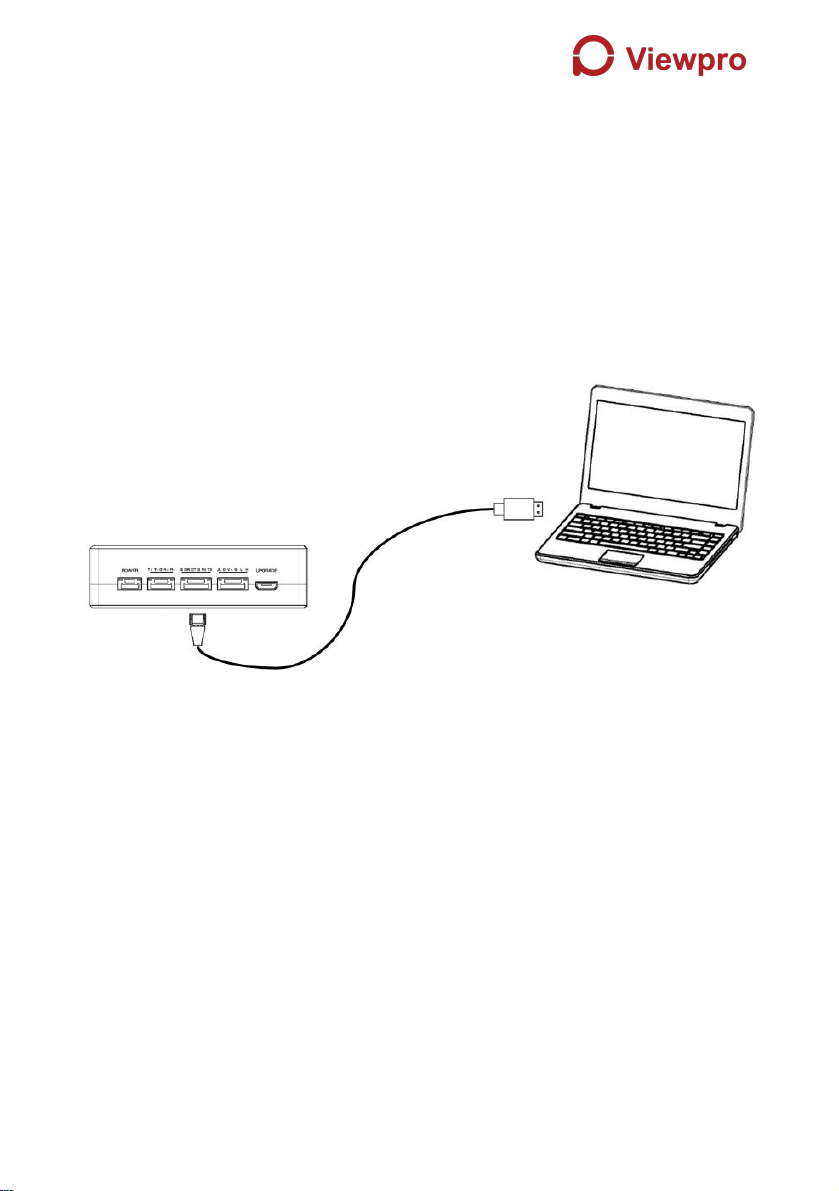
4.7. Upgrade......................................................................................... 27
4.8. View Live Video............................................................................ 28
5. Applications............................................................................................... 29
5.1. Applications of system in detail.................................................. 29
5.2. Applications of RC........................................................................29
5.2.1. FRSKY remote controller................................................ 30
5.2.2. FUTABA remote controller..............................................31
5.3. Telemetry connection...................................................................31
6. Notes.......................................................................................................... 31
6.1. Link performance..........................................................................31

6.2. How to select Frequency.............................................................33
6.3. Firmware update...........................................................................36
6.4. Bind operation............................................................................... 37
6.5. Telemetry & RC............................................................................ 37
7. FAQ.............................................................................................................38
1
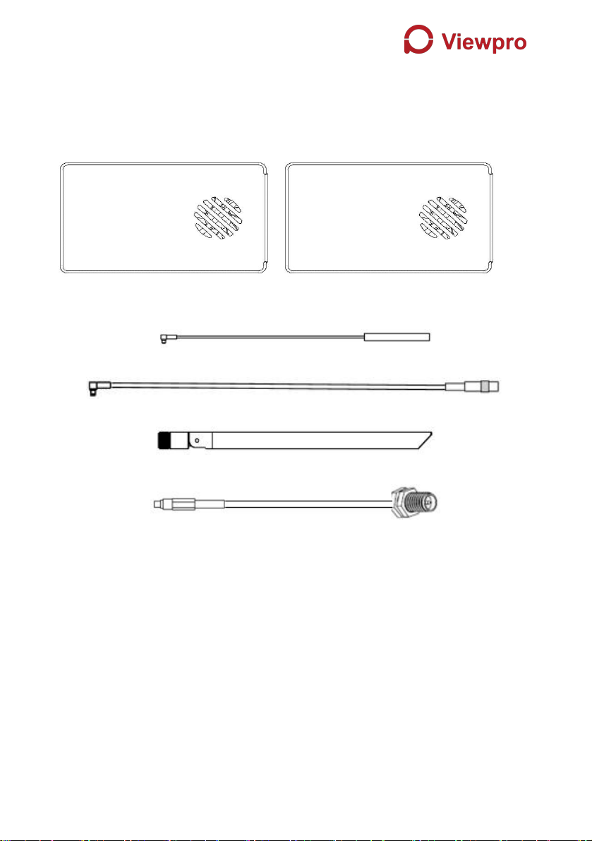
1. Package Contents
Air Unit & Ground Unit
Air unit antenna & feeder line ×2
(2.4G antenna for air unit)
(2.4G feeder extension line for air unit)
(1.4G antenna for air unit)
(1.4G feeder extension line for air unit)
Use feeder extension line of air unit

2
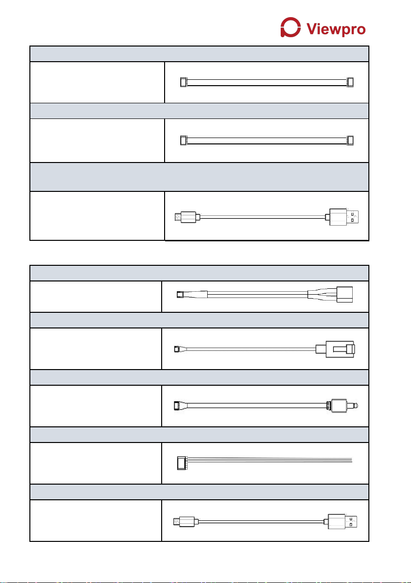
Ground unit antenna & feeder line ×2
(2.4G antenna for ground unit)
(2.4G feeder line for ground unit)
(1.4G antenna for ground unit)
(1.4G feeder line for ground unit)
Air Unit Cables
Power cable x1
This is used to connect the
output of a battery to the power
input of the air unit.
RJ45 cable x1
This is used to connect the
ETH output of camera to the
ETH input of the air unit.
3
RC cable x1
This is used to connect the
PPM/S.bus port of flight
controller to the RC port of the
air unit.
Serial cable x1
This is used to connect the
telemetry port of flight controller
to the serial port of the air unit.
USB cable(Micro to Type-A)×1
This is used to connect the
USB port of a PC or a cell
phone, to the Micro USB port of
the ground unit.
Ground Unit Cables
Power cable x1
This is used to connect the
output of a battery to the
power input of the air unit.
RJ45 cable x1
This is used to connect the
ETH output of ground unit to
the ETH input of a PC or
laptop.
RC cable x1
This is used to connect the
training port of a remote
controller to the RC port of the
ground unit.
Serial cable (UART) x1
This is used to connect the
telemetry port of ground
station to the serial port of the
ground unit.
USB cable (Micro to Type-A)×1 (share with air unit one)
This is used to connect the
USB port of a PC or a cell
phone, to the Micro USB port
of the ground unit.

4
2. Product Description
2.1. Parameters
Frequency
1.400GHz-1.495GHz, 2.4GHz-2.483GHz,
(Customizable)
Band width
2.5MHz (uplink), 10MHz(downlink)
Power
27dBm (FCC), 20dBm (CE)
Modulation
OFDM
Constellation
BPSK, QPSK, 16QAM
FEC
LDPC (1/2, 2/3, 3/4, 5/6)
Duplex
TDD
Downlink throughput
2.3Mbps ~ 12Mbps
Uplink throughput
115.2kbps
Encryption
AES 128, AES 256
Interface
Ethernet, Serial, PPM/S.BUS
Consumption
6.8W(ground unit) / 7.8W(air unit)
Dimension
77.8X47.3X23.5mm
Weight
97g
Rated voltage/current
DC12V/1.2A (or 3S lithium battery)
Working temperature
-30°C ~55°C
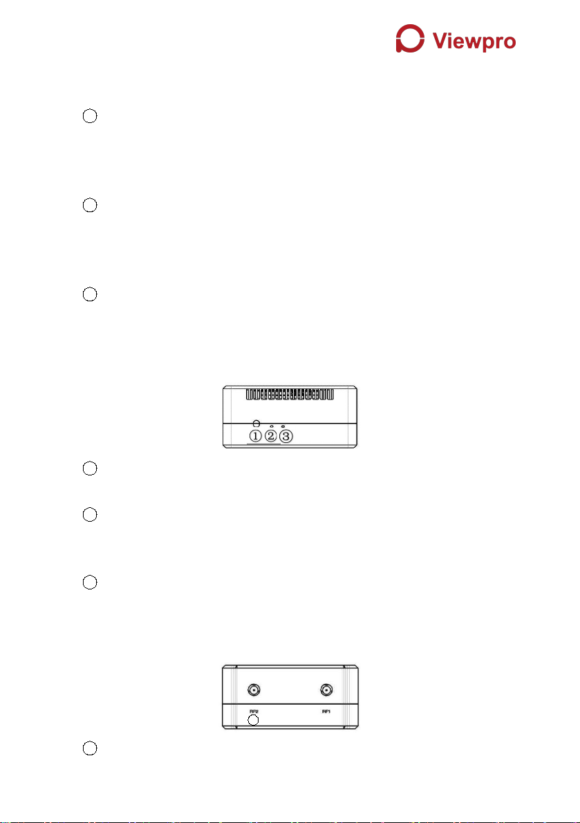
2.2. Air Unit Interfaces
1Power Input Port
Connect a 12V power source to this port. The power source can be from a battery,
or can be from a power adaptor when the ground unit is upgraded on the ground.
The power supply recommended 3s battery.
2RJ45 Port
②
③
④
⑤
①
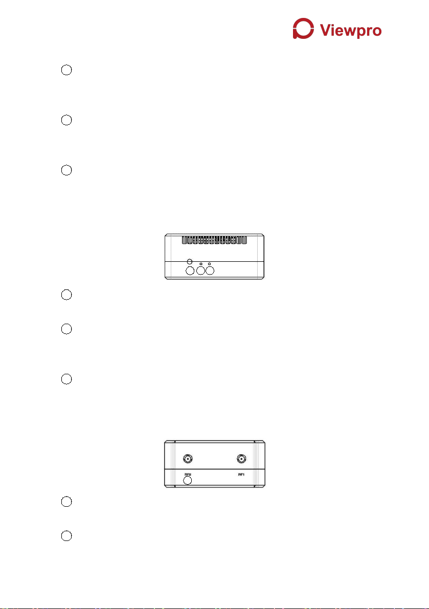
5
Connect the ethernet output of camera to the ethernet input of the air unit.
3Serial Port (UART)
Connect this port to the telemetry port of a flight controller for telemetry
communication with the ground unit. UART signal: LVCMOS-3.3V.
4Remote Control Port (RC)
Connect this port to the PPM/S.Bus port of a flight controller for remote control
communication with the ground unit. Pin V + can provide 5V power supply.
5Micro USB Port
Connect this port to the USB port of a PC or Laptop, and use the Viewpro PC
program to upgrade firmware on the air unit.
1Bind Button
Press this button to perform the binding operation.
2LED 1
When this LED is on, it means the air-to-ground link is connected; when this LED
is off, it means the air-to-ground link is disconnected. (Not available for air unit)
3LED 2
When this LED is on, it means the ground -to-air link is connected; when this LED
is off, it means the ground -to-air link is disconnected. (Not available for air unit)
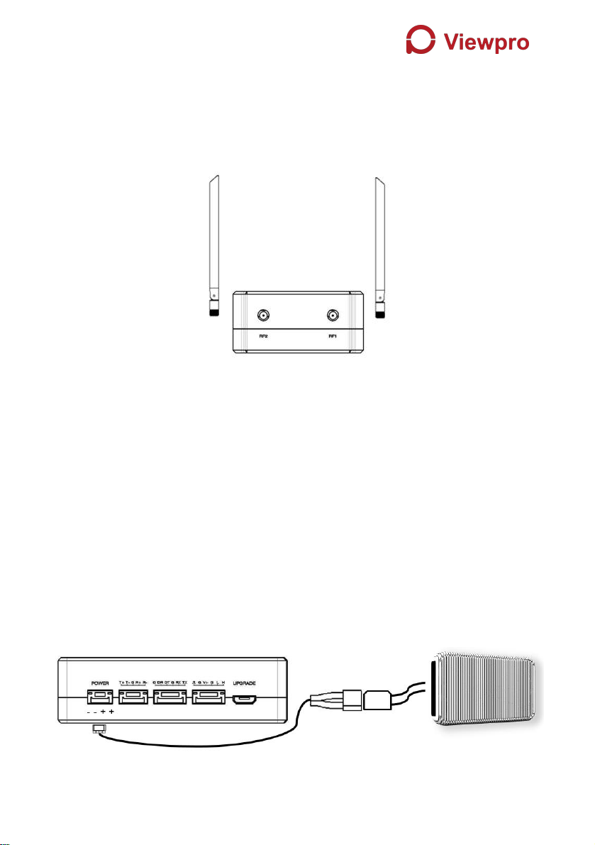
1RF2 Port
Connect the 2nd air unit antenna to this port.
2RF1 Port
Connect the 1st air unit antenna to this port.
1
1
3
2
②
6
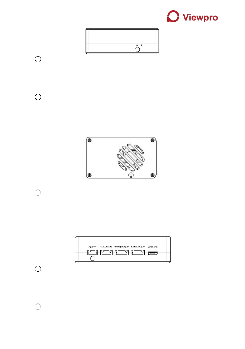
1LED3
When this LED is flickering, it means the data link of the Ethernet network is
connected; when this LED is off, it means the data link of the Ethernet network is
disconnected.
2LED4
When this LED is on, it means the physical link of the ethernet port is connected;
when this LED is off, it means the physical link of the ethernet port is
disconnected.
1Fan Ventilation Outlet
Don’t block this fan ventilation outlet to ensure effective cooling.
2.3. Ground Unit Interfaces
1Power Input Port
Connect 12V power source to this port. The power source can be from a battery,
or can be from a power adaptor when the ground unit is upgraded on the ground.
The power supply recommended 3s battery.
2RJ45 Port
1
1
②
③
④
⑤
②
7
Connect this ethernet output port to the ethernet input port of a camera using the
supplied RJ45 cable.
3Serial Port (UART)
Connect this port to the telemetry port of a remote controller, or the serial port of
a ground control station to setup a telemetry link between the drone and the
remote controller or the ground control station. UART singal: LVCMOS-3.3V.
4Remote Control Port (RC)
Connect this port to the training PPM/S.bus port of a remote controller. Remote
controller can use ViUlinxTM uplink to communicate with the drone. Pin V + can
provide 5V power supply.
5Micro USB Port
Connect this port to the USB port of a PC or Laptop, and use the Viewpro PC
program to upgrade firmware on the air unit.
1Bind Button
Press this button to perform the binding operation.
2LED 1
When this LED is on, it means the air-to-ground link is connected; when this LED
is off, it means the air-to-ground link is disconnected.
3LED 2
When this LED is on, it means the ground -to-air link is connected; when this LED
is off, it means the ground -to-air link is disconnected.
1RF2 Port
1
②

8
Connect the 2nd ground unit antenna to this port.
2RF1 Port
Connect the 1st ground unit antenna to this port.
1LED 1
When this LED is flickering, it means the data link of the Ethernet network is
connected; when this LED is off, it means the data link of the Ethernet network is
disconnected.
2LED 2
When this LED is on, it means the physical link of the ethernet port is connected;
when this LED is off, it means the physical link of the ethernet port is
disconnected.
1Fan Ventilation Outlet
Don’t block this fan ventilation outlet to ensure effective cooling.
3. Installation
3.1. Air Unit Installation
3.1.1. Antenna installation
2.4G air unit
1
②
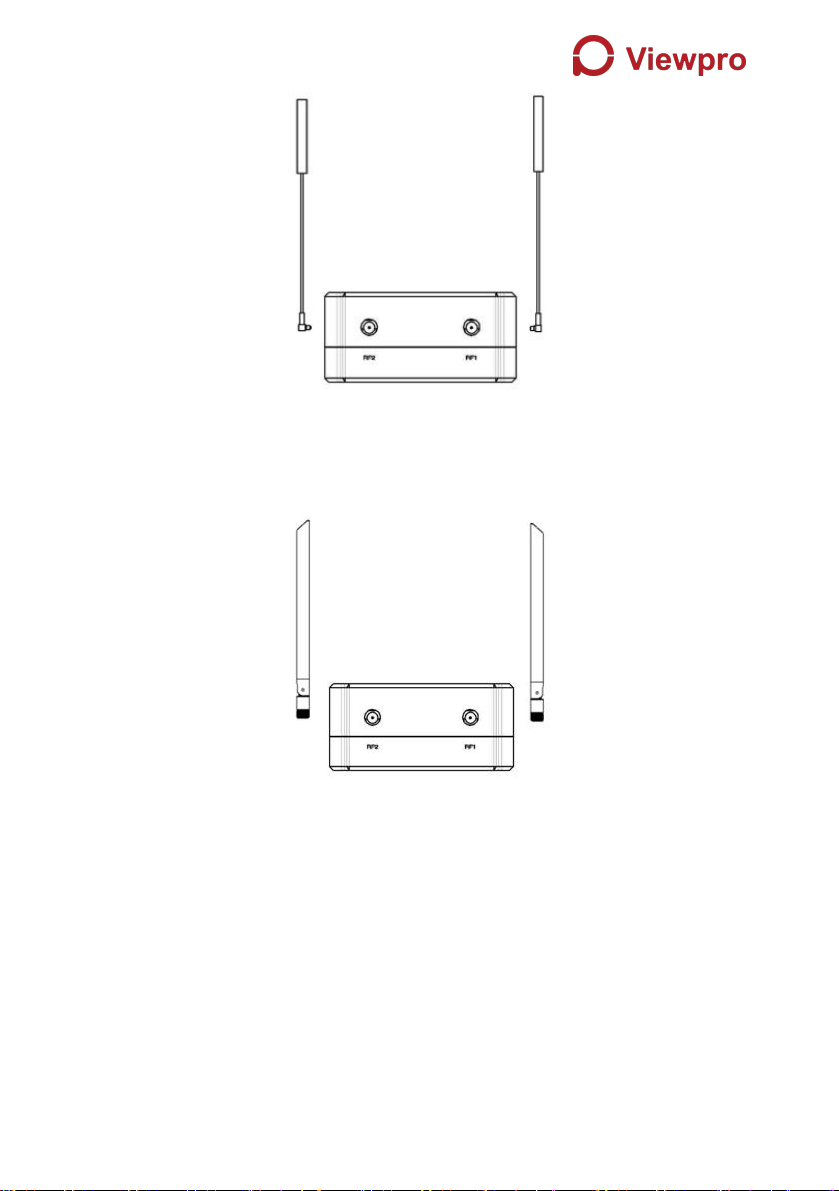
9
Insert the air unit antennas into the RF ports. Antenna clicks in when properly
installed.
1.4G air unit
Insert the air unit antennas into the RF ports with RF cables. RF cables clicks in
when properly installed.
Note:
(1)To avoid equipment damage, install antennas before powering on the units.
(2)When install air unit to drone, avoid the antennas being blocked by parts of the
drone.
(3)Both antennas need to be installed.
(4) Ensure the antenna connector is vertical to the module when it is pushed into
the RF port.
(5)When uninstall the antenna, hold the connector and pull it out of the RF port.
Do not pull the cable.
10
3.1.2. Power supply
Pin-out: - - + +. Insert the four-pin connector of supplied power cable to the
power port of the air unit and connect the orange power connect of supplied
power cable to a battery output, or the power supply port of a drone.
Recommended voltage is 12V.
Note:
(1)To avoid equipment damage, install antennas before powering on the units.
(2)Recommended rated voltage/current is DC12V/1.2A (or 3S lithium battery).

11
3.1.3. Connection to camera
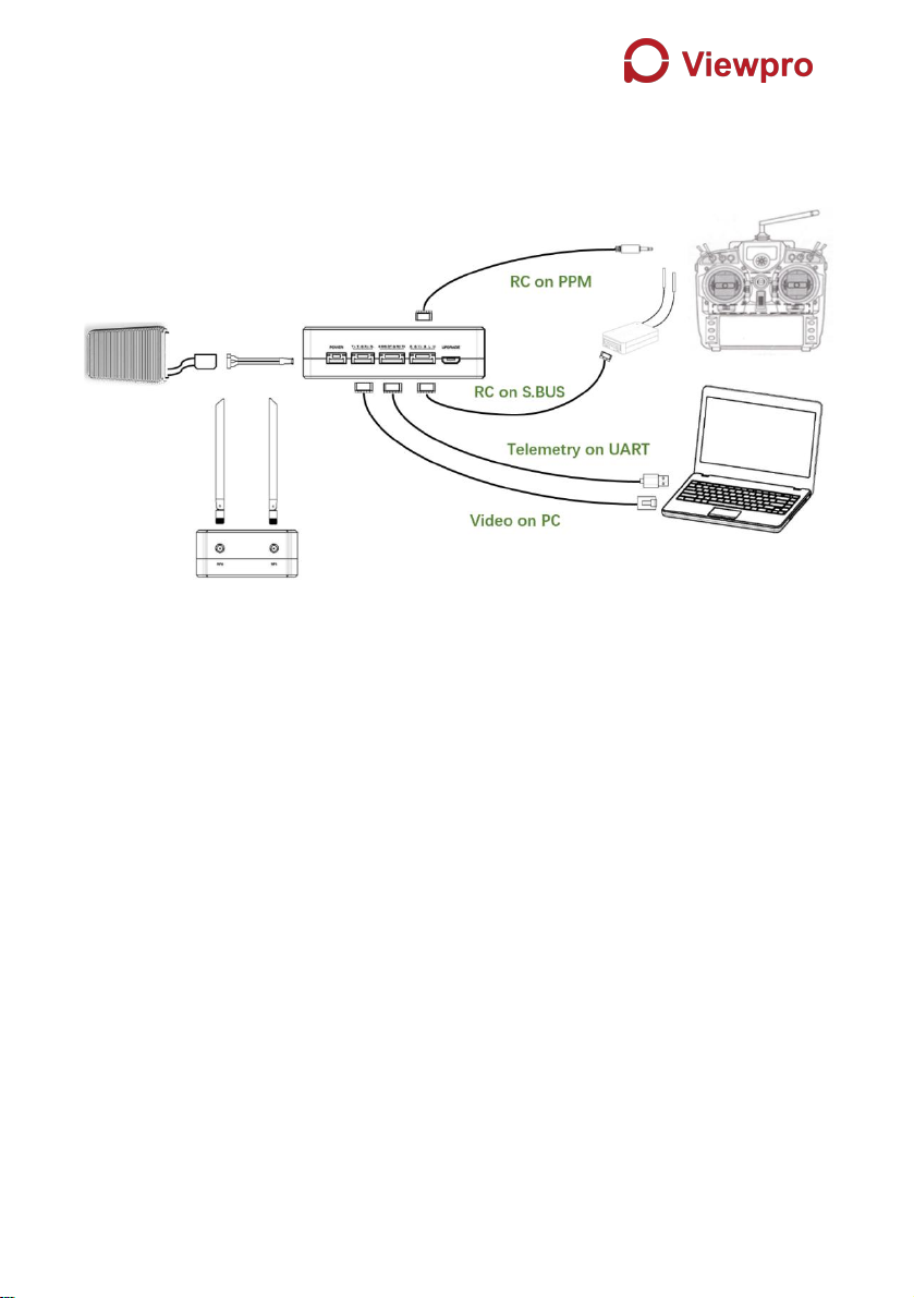
Connect the ethernet video output port to the ethernet video input port of the air unit.

12
3.1.4. Connection to flight controller (RC & telemetry)
Insert the six-pin connector of supplied serial cable to the serial port of the air unit
and connect the other end of the serial cable to the telemetry port of a flight
controller.
Insert the supplied RC cable to the RC port of the air unit and connect the other end
of the RC cable to the PPM/S.BUS port of a flight controller.
13
3.2. Ground Unit Installation
3.2.1. Antenna installation
Insert the air unit antennas into the RF ports with RF cables. RF cables clicks in
when properly installed.
Note:
(1)To avoid equipment damage, install antennas before powering on the units.
(2)When install air unit to drone, avoid the antennas being blocked by parts of the
drone.
(3)Both antennas need to be installed.
(4) Ensure the antenna connector is vertical to the module when it is pushed into
the RF port.
(5)When uninstall the antenna, hold the connector and pull it out of the RF port. Do
not pull the cable.
3.2.2. Power supply
14
Insert the power connector of the power adaptor into the charging port of the ground
unit and insert into the aerial plug into an electrical outlet to fully charge the battery
of ground unit. Recommended voltage is 12V.
Note:
(1) Recommended rated voltage/current is DC12V/1.2A (or 3S lithium battery).
(2) To avoid equipment damage, install antennas before powering on the units.
3.2.3. Telemetry connection
Insert the six-pin connector of supplied serial cable to the serial port of the ground
unit and connect the other end of supplied serial cable to the telemetry port of the
ground control station.
Note:
(1) Ensure the baud rate of ground station and the baud rate of Viewpro module
are configured correctly.
(2) Ensure the serial cable sequence matches the interface definition of Viewpro
module.

15
3.2.4. Connection to remote controller
Using PPM mode: Insert the training connector of the supplied RC cable to the
training port of a remote controller and connect the six-pin connector of the RC
cable to the RC port of the ground unit.
Using S.BUS mode: Insert the six-pin connector of the RC cable to the RC port of
the ground unit, the other end connect the S.BUS receiver, and the S.BUS receiver
communicates with the remote controller in wireless communication.
Note:
(1) Ensure the remote controller is in training mode, it is configured to the PPM or
S. BUS working mode.
(2) Ensure the RC cable sequence matches the interface definition of Viewpro
module.
(3) If the S.BUS receiver is used, the working frequency of the receiver and the
Viewpro module should be guaranteed with a certain degree of isolation.
3.2.5. Setup video output

16
Ground unit has one way of outputting received video, to a PC or laptop.
Note:
(1) To view the video on PC or Laptop, connect the ethernet port of the ground unit
to the ethernet port of a PC or a Laptop, the IP address of the PC is configured
correctly.
3.2.6. Use Viewpro System
1. Connect antennas to RF ports of the air unit.
2. Connect camera ethernet output to ethernet input port of the air unit.
3. Connect the PPM/S.bus port of the flight controller to the RC port of the air
unit.
4. Connect the flight controller telemetry port to the serial port of the air unit.
5. Turn on the camera and set the video format to 720p or 1080p.
6. Connect a 12V DC power to the power port of the air unit and turn on the
power.
17
7. If latest firmware is desired, connect the air unit to a PC or a Laptop using
USB cable and run Viewpro PC program to upgrade the firmware of the air
unit to the latest one.
1. Connect antennas to RF ports of the ground unit.
2. Adjust the remote controller to the training mode, if PPM mode is used, the
remote controller interface at the ground end is connected to the training
port of the remote control. If S.BUS mode is used, the cable connection
between the S.BUS receiver and the ground end need to be established,
and the connection between the receiver and the remote control need to be
established.
3. Connect the USB port of ground control station to the serial port of the
ground unit with TTL-USB cable if you want to use Viewpro’s telemetry link.
4. If video view on a PC or a Laptop is desired, connect a PC or a Laptop to
the ethernet port of the ground unit.
5. Connect a 12V DC power to the power port of the ground unit and turn on
the power.
6. If latest firmware is desired, connect the ground unit to a PC or a Laptop
using USB cable and run Viewpro PC program to upgrade the firmware of
the ground unit to the latest one.
Table of contents
Other Viewpro Transmitter manuals

Popular Transmitter manuals by other brands


Crestron
Crestron DM-TX-201-C Operations & installation guide

Williams Sound
Williams Sound PERSONAL PA T35 Manual and user guide

AMG
AMG AMG2683 instruction manual

AMEC
AMEC AIS SART PLOMO-500 manual

Roger Technology
Roger Technology R80/TX102 instructions

B+B Sensors
B+B Sensors 0555 0035-01 operating manual