Viewpro DDL14H-HUSPB User manual

1
Video and Data Transmitter
DDL14H-HUSPB
User Manual
www.viewprotech.com

2
Contents
1. Package Contents................................................................................ 3
2. Product Description............................................................................. 5
2.1. Air Unit Interfaces.....................................................................5
2.2. Ground Unit Interfaces............................................................. 7
3. Installation........................................................................................... 9
3.1. Air Unit Installation...................................................................9
3.1.1. Antenna installation...................................................... 9
3.1.2. Power supply............................................................... 11
3.1.3. Connection to camera................................................. 11
3.1.4. Connection to flight controller (RC & telemetry)........ 12
3.2. Ground Unit Installation......................................................... 13
3.2.1. Antenna installation.................................................... 13
3.2.2. Power supply............................................................... 14
3.2.3. Connection to ground control station......................... 14
3.2.4. Connection to remote controller................................ 15
3.2.5. Setup video output...................................................... 16
3.2.6. Use ViuLinxTM System................................................... 17
4. Software.............................................................................................19
4.1. Installation.............................................................................. 19
4.2. Language Selection................................................................. 21
4.3. Device Info.............................................................................. 22
4.4. Status...................................................................................... 22
4.5. Configuration.......................................................................... 23
4.5.1. Mode configuration..................................................... 23
4.5.2. Baud rate configuration...............................................25
4.5.3. Remote control mode configuration...........................25
4.6. Frequency Scan.......................................................................25
4.7. Upgrade.................................................................................. 27
4.8. View Live Video.......................................................................27
4.8.1. On phone..................................................................... 27
4.8.2. On monitor.................................................................. 27

3
1. Package Contents
Air Unit & Ground
Unit
Air unit antenna ×2
(2.4G antenna for air unit)
(1.4G antenna for air unit)
Ground unit antenna× 2
Air Unit Cables
Power cable x1
This is used to connect the
output of a battery to the power
input of the air unit.
HDMI cable (Micro to Micro) ×1
This is used to connect the HDMI
output of camera to the HDMI
input of the air unit.
RC cable x1

4
This is used to connect the
PPM/S.bus port of flight
controller to the RC port of the
air unit.
Serial cable x1
This is used to connect the
telemetry port of flight controller
to the serial port of the air unit.
USB cable(Micro to Type-A)×1
This is used to connect the USB
port of a PC or a cell phone, to
the Micro USB port of the ground
unit.
Ground Unit Cables
Power cable x1
This is used to connect the
output of a battery to the power
input of the air unit.
HDMI cable (Mini to TYPE A) ×1
This is used to connect the HDMI
output of ground unit to the
HDMI input of the monitor.
RC cable x1
This is used to connect the
training port of a remote
controller to the RC port of the
ground unit.
Serial cable x1
This is used to connect the
telemetry port of ground station
to the serial port of the ground
unit.
USB cable (Micro to Type-A)×1
Connect the USB port of a PC or a
cell phone, to the Micro USB port
of the ground unit.

5
2. Product Description
2.1. Air Unit Interfaces
1Power Input Port
Connect a 7V ~ 16V power source to this port. The power source can be from the drone
when the air unit is used for drone operation, or can be from a power adaptor when the
air unit is upgraded on the ground.
2Serial Port(UART)
Connect this port to the telemetry port of a flight controller for telemetry
communication with the ground unit.
3Remote Control Port(RC)
Connect this port to the PPM/S.bus port of a flight controller for remote control
communication with the ground unit.
4Micro USB Port
Connect this port to the USB port of a PC or Laptop, and use the Taisync PC program to
upgrade firmware on the air unit.
1HDMI Port
Connect the HDMI output of a camera to the HDMI input of the air unit.
③
②
1
④
1

6
1Bind Button
Press this button to perform the binding operation.
2LED 1
When this LED is on, it means the air-to-ground link is connected; when this LED is off, it
means the air-to-ground link is disconnected.
3LED 2
When this LED is on, it means the ground -to-air link is connected; when this LED is off, it
means the ground -to-air link is disconnected.
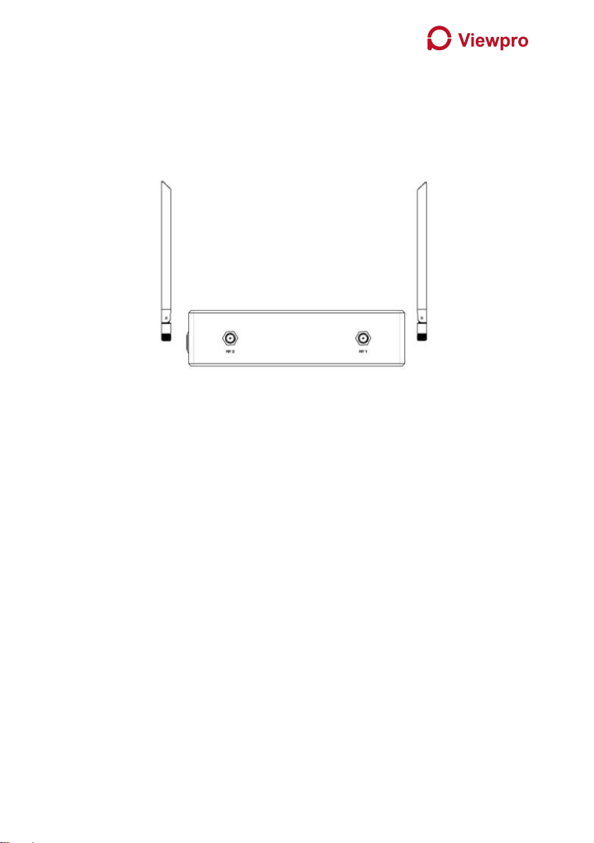
1RF2 Port
Connect the 2nd air unit antenna to this port.
2RF1 Port
Connect the 2nd air unit antenna to this port.
1Fan Ventilation Outlet
Don’t block this fan ventilation outlet to ensure effective cooling.
1
2
1
1
②
③

7
2.2. Ground Unit Interfaces
1HDMI Port
Connect this mini HDMI output port to the HDMI input port of a display device using the
supplied Mini HDMI to HDMI cable.
2Micro USB Port
Connect this port to the USB port of a PC or Laptop, and use the Taisync PC program to
upgrade firmware and set parameters on the air unit.
3USB Port
Connect this port to the Lightning port of an iPhone, or to the USB port of an Android phone
and use ViULinxTM cell phone APP to watch live video play and set parameters of the air and
ground unit.
4Serial Port(UART)
Connect this port to the telemetry port of a remote controller, or the serial port of a ground
control station to setup a telemetry link between the drone and the remote controller or the
ground control station.
5Remote Control Port(RC)
Connect this port to the training PPM/S.bus port of a remote controller. Remote controller can
use ViUlinxTM uplink to communicate with the drone.
1
②
③
④
⑤
1
②
③
④

8
1Charging Port
Connect this port to the supplied power adaptor to charge the battery in the ground unit.
2Power Button
When the ground unit is off, push this button once to turn on the ground unit. When the
ground unit is on, push this button once to turn off the ground unit.
3Fan Ventilation Outlet
Don’t block this fan ventilation outlet to ensure effective cooling.
4Fan Ventilation Outlet
Don’t block this fan ventilation outlet to ensure effective cooling.
1RF2 Port
Connect the ground unit antenna to this port.
2RF1 Port
Connect the 2nd ground unit antenna to this port.
1Bind Button
Press this button to perform the binding operation.
1
②
1

9
1LED 1
When this LED is on, it means the air-to-ground link is connected; when this LED is off, it
means the air-to-ground link is disconnected.
2LED 2
When this LED is on, it means the ground -to-air link is connected; when this LED is off, it
means the ground -to-air link is disconnected.
3. Installation
3.1. Air Unit Installation
3.1.1. Antenna installation
2.4G air unit
1
②

10
Insert the air unit antennas into the RF ports. Antenna clicks in when properly installed.
1.4G air unit
Insert the air unit antennas into the RF ports with RF cables. RF cables clicks in when
properly installed.
Note:
(1) To avoid equipment damage, install antennas before powering on the units.
(2) When install air unit to drone, avoid the antennas being blocked by parts of the drone.
(3) Both antennas need to be installed.
(4) Ensure the antenna connector is vertical to the module when it is pushed into the RF
port.
(5) When uninstall the antenna, hold the connector and pull it out of the RF port. Do not
pull the cable.

11
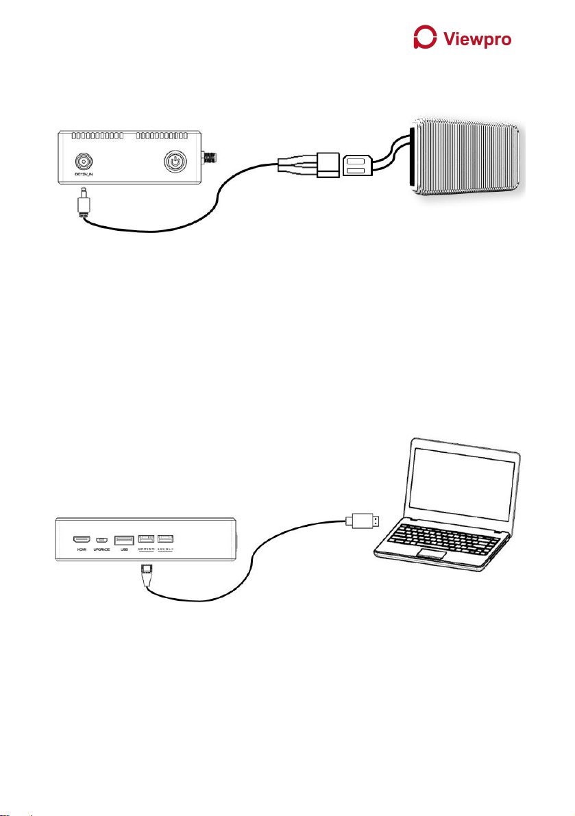
3.1.2. Power supply
Insert the four-pin connector of supplied power cable to the power port of the air unit
and connect the orange power connect of supplied power cable to a battery output, or
the power supply port of a drone. Power supply range is 7V~16V with recommended
voltage of 12V.
Note:
(1) To avoid equipment damage, install antennas before powering on the units.
(2) Recommended voltage is 7V~16V.
3.1.3. Connection to camera
Connect the HDMI video output port to the HDMI video input port of the air unit.

12
3.1.4. Connection to flight controller (RC & telemetry)
Insert the six-pin connector of supplied serial cable to the serial port of the air unit and
connect the other end of the serial cable to the telemetry port of a flight controller.
Insert the supplied RC cable to the RC port of the air unit and connect the other end of the
RC cable to the PPM/S.bus port of a flight controller.
13
3.2. Ground Unit Installation
3.2.1. Antenna installation
Screw the ground unit antennas onto the RF ports. Make sure the antennas are tightly
installed.
Note:
(1) To avoid equipment damage, install antennas before powering on the units.
(2) Ensure the antenna connector is vertical to the module when it is screwed onto the RF
port. Screw the antenna tightly to avoid loose connection, but do not overtighten the
antenna to avoid damaging the antenna.
(3) Both antennas need to be installed.
(4) Adjust the antenna to be vertical to the ground during operation.
14
3.2.2. Power supply
Insert the power connector of the power adaptor into the charging port of the ground unit
and insert into the aerial plug into an electrical outlet to fully charge the battery of ground
unit. Power supply range is 7V~16V with recommended voltage of 12V.
Note:
(1) Charging voltage is 12V.
(2) To avoid equipment damage, install antennas before powering on the units.
3.2.3. Connection to ground control station
Insert the six-pin connector of supplied serial cable to the serial port of the ground unit and
connect the other end of supplied serial cable to the telemetry port of the ground control
station.
Note:
(1) Ensure the baud rate is configurated correctly.
(2) Ensure the interface sequence is connected correctly.

15
3.2.4. Connection to remote controller
Insert the training connector of the supplied RC cable to the training port of a remote
controller and connect the six-pin connector of the RC cable to the PPM/S.bus port of the
ground unit.
Note:
(1) Ensure the remote controller is in training mode.
(2) Ensure the interface sequence is connected correctly.

16
3.2.5. Setup video output
Ground unit has two ways of outputting received video, either to a monitor, or to a
cellphone.
Note:
(1) To view the video on monitor, connect the mini HDMI port of the ground unit to the
HDMI port of a monitor, then connect the USB port of the ground unit to your cell phone.
Run ViULinxTM on the cell phone and select the video output to be HDMI.
(2) To view the video on cell phone, connect the USB port of the ground unit to your cell
phone. Run ViULinxTM on the cell phone and select the video output to be Cell Phone. Click
play button to start the video.

17
3.2.6. Use ViuLinxTM System
1. Connect antennas to RF ports of the air unit.
2. Connect camera HDMI output to HDMI port of the air unit.
3. Connect the PPM/S.bus port of the flight controller to the RC port of the air unit.
4. Connect the flight controller telemetry port to the serial port of the air unit.
5. Turn on the camera and set the video format to 720p or 1080p.
6. Connect a 12V DC power to the power port of the air unit and turn on the power.
7. If latest firmware is desired, connect the air unit to a PC or a Laptop using USB cable
and run ViuLinxTMPC program to upgrade the firmware of the air unit to the latest
one.

18
1. Connect antennas to RF ports of the ground unit.
2. Connect the remote controller’s PPM/S.bus output to the RC port of the ground unit
if you want to use ViuLinx’s command uplink.
3. Connect the USB port of ground control station to the serial port of the ground unit
with TTL-USB cable if you want to use ViuLinx’s telemetry uplink.
4. Connect cell phone to the micro USB port of the ground unit.
5. If video view on a monitor is desired, connect a monitor to the HMDI port of the
ground unit.
6. Turn on the ground unit.
7. If latest firmware is desired, connect the ground unit to a PC or a Laptop using USB
cable and run ViULinxTM PC program to upgrade the firmware of the air unit to the
latest one.
8. After downlink and uplink are connected, both LEDs will be on.
9. Run ViULinxTM APP on your cell phone. You can set the parameters of air unit and
ground unit, monitor link status.

19
4. Software
4.1. Installation
We provide program installation files, program file name: Taisync Wireless App Setup.exe.
The installer icon is as follows:
Double-click the installer to install and customize the program installation directory. After
configuration, click the “Next” button to jump to the next step. To cancel the installation,
click the “Cancel” button.
Check the Generate desktop shortcut. If it is not checked, the desktop shortcut will not be
generated. After configuration, click the “Next” button to jump to the next step. To rewind
the previous step, click the “Back” button. To cancel the installation, click the Cancel button.

20
Click “Install” to proceed with the installation. To rewind the previous step, click the “Back”
button. To cancel the installation, click the “Cancel” button.
Note: Please turn off the firewall software, otherwise the firewall may prevent the driver
from being installed when the driver is installed.
Table of contents
Other Viewpro Transmitter manuals

Popular Transmitter manuals by other brands


Endress+Hauser
Endress+Hauser iTEMP TMT82 Brief operating instructions

NOSHOK
NOSHOK 850 Series operating instructions

Emerson
Emerson Rosemount 2051L quick start guide

E+E Elektronik
E+E Elektronik EE210 user guide

Jasco
Jasco GE SmartSecurity 51147 user manual

SY Electronics
SY Electronics MFT-31C user manual


