Vighnaharta VCOP GOLD User manual

Vighnaharta Technologies Pvt. Ltd.
2nd Floor,Karanjkar Estate,
S.N.11/11,Nanded Gaon,
Pune-411041
Tel no.: + 1 01103325 , Sales: + 1 011033260
Email: sales@vighnaharta.in | Website: http://www.vighnaharta.in
Prepared By: SKP
Reviewed By: JG
Approved By: AG
Doc No.: RASS/R&D/VCOP_Gold_UM_1_2
Rev No.: 1_2
Eff Date: 04/11/201
VC O P GOL D
US E R MA N UA L
Mfg. By:
Vighnaharta Technologies Pvt. Ltd.
2nd Floor,Karanjkar Estate,S.N.11/11,Nanded Gaon,Pune-411041
Contact no.: + 1 01103325 (Landline) Sales: + 1 011033260
Email: sales@vighnaharta.in | Website: http://www.vighnaharta.in

VCOP Gold User Manual
Vighnaharta Technologies Pvt. Ltd. Page 2 of 44
Table Of Contents
T
ABLE
O
F
C
ONTENT
............................................................................................. 2
1. PRODUCT DE CRIPTION ............................................................................. 4
1.1
O
VERVIEW
.................................................................................................... 4
1.2
F
EATURE
.................................................................................................... 5
1.3
O
PTIONAL
A
CCE ORIE
P
ROVIDED
W
ITH
T
HE
Y TEM
.......................................... 5
1.4
T
ECHNICAL
PECIFICATION
.............................................................................. 5
2. IN TALLATION PROCEDURE ....................................................................... 7
2.1
P
REREQUI ITE
............................................................................................. 7
2.2
I
N TALLING THE UNIT AT THE U ER PREMI E
....................................................... 7
2.3
W
IRING
D
IAGRAM
......................................................................................... 8
3. GETTING TARTED ...................................................................................... 9
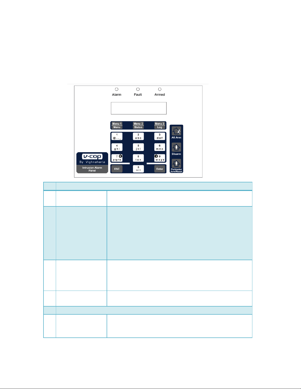
3.1
U
NDER TANDING
C
ONTROL
O
N
F
RONT
P
ANEL
..................................................... 9
3.2
P
OWER
ON
T
HE
Y TEM
............................................................................... 10
3.3
V
IEW
E
VENT
L
OG
......................................................................................... 10
3.4
ETTING
D
ATE AND
T
IME
............................................................................... 11
3.5
R
EBOOT THE
Y TEM
.................................................................................... 11
4. CONFIGURING THE Y TEM ........................................................................ 13
4.1 IN TALLER ............................................................................................. 13
4.1.1 Set PIN ................................................................................................ 13
4.1.2 Delete Log ........................................................................................... 14
4.2
U ER ........................................................................................................ 15
4.2.1 User Configuration 1 / 5 ......................................................................... 16
4.2.2 User Configuration 2 / 5 ........................................................................ 19
4.2.3 User Configuration 3 / 5 ........................................................................ 20
4.2.4 ey Fob ............................................................................................... 20
4.2.5 User configuration 4 / 5 ......................................................................... 22
4.2.6 User configuration 5/5 ........................................................................... 23
5. CONFIGURING G M .................................................................................. 24
5.1
V
OICE NUMBER CONFIGURATION
..................................................................... 24
5.2
M
NUMBER CONFIGURATION
....................................................................... 25
5.3
A
UTHENTICATED
M
NUMBER CONFIGURATION
............................................... 26

VCOP Gold User Manual
Vighnaharta Technologies Pvt. Ltd. Page 3 of 44
5.4
C
OMM
.
T
E T FOR
C
OMMUNICATION TE TING
...................................................... 27
5.5
C
ONFIGURATION BY ENDING
M .................................................................. 28
5.5.1 Configuring SMS and voice reporting numbers Error! Bookmark not defined.
5.5.2 Voice Record and Playback by SMS ......................................................... 28
5.5.3 Arm, Perimeter Arm and Disarm by SMS ........ Error! Bookmark not defined.
6. CONFIGURING P TN .................................................................................... 30
6.1
V
OICE NUMBER CONFIGURATION
..................................................................... 31
6.1.1 Voice number types with examples ......................................................... 31
6.1.2 To configure voice numbers .................................................................... 32
6.2
V
OICE
M
E AGE
R
ECORDING
.......................................................................... 33
6.3
V
OICE
M
E AGE
P
LAYBACK
............................................................................ 33
7. CID ........................................................................................................... 34
7.1
C
ONFIGURATION OF
CID
REPORTING NUMBER
.................................................. 34
7.2
C
OMM
T
E T FOR COMMUNICATION TE TING
....................................................... 35
8. IP ETTING ............................................................................................... 37
9. OPERATION .............................................................................................. 40
9.1 A
RMING THE Y TEM
................................................................................... 40
9.2 D
I ARMING THE Y TEM
............................................................................... 40
9.3 P
ERIMETER
A
RM THE Y TEM
......................................................................... 40
9.4 ENTRY/EXIT
D
ELAY
................................................................................. 41
9.5 A
LARM
R
EPORTING
..................................................................................... 41
APPENDIX ........................................................................................................ 42
Connector Details for zones ............................................................................. 42
SYSTEM FAULTS LIST ..................................................................................... 43
GLO ARY ........................................................................................................ 44

VCOP Gold User Manual
Vighnaharta Technologies Pvt. Ltd. Page 4 of 44
1. Product Description
1.1 Overview
VCOP Gold is a sophisticated home / office security system for protection against burglary or
property damage. The system is designed to detect intrusion (unauthorized) entry in to building or
area with the help of sensors. The system is kept at the user premises. System can read inputs
from wired as well as wireless sensors. User can configure various parameters like zones, entry /
exit delay, and contact numbers with help of key pad. LCD display on the front panel indicates the
various activities. LED and buzzers are also used to report emergency. At the same time system
reports to different users by sending SMS or voice call and central stations with the help of contact
IDs.
VCOP Gold has following basic models.
No. Model Operation Pre-requisite
1 VCOP Gold GSM
Wired
•
Alert through sms and voice call.
SIM card
2 VCOP Gold GSM
Hybrid
•Alert through sms and voice call.
•Remote configuration through
sms/ android app.
SIM card
3 VCOP Gold
Standalone
•
Alert display on panel N/A
4 VCOP Gold
PSTN Wired
•Alert through voice call only.
Telephone line
5 VCOP Gold
PSTN Hybrid
•Alert through voice call.
•Remote configuration through
android app.
Telephone line
6 VCOP GOLD IP
•
Alert through Ethernet (TCP IP)
connectivity.
LAN Connection and Internet
Connectivity, CMS monitoring

VCOP Gold User Manual
Vighnaharta Technologies Pvt. Ltd. Page 5 of 44
1.2 Features
•Battery backup* of 24 hours.
•Sends alert call / sms to 10 mobile numbers / landline numbers.
•Key fob has panic key.
•Can connect 8 wired, 1 smoke and 32 wireless zones (including 4 key fobs – panic zones).
•Zones (sensors) include gas leak detector, door magnetic sensor, fire detector, smoke
detector, PIR sensors, vibration detector.
•Auto arm and disarm facility for a particular zone.
•Voice / sms number configuration through sms / android application.
•Voice recording through sms.
Note: Battery backup* - This back up is claimed without sensors connected to the unit.
1.3 Optional Accessories Provided With The ystem
1.4
Technical pecification
Power upply Adaptor of 15V/2A or External battery of 12V /1.2AH. Rechargeable
battery backup.
Item
Arming / Disarming wireless key fob
Wired Sensors for smoke, intrusion, motion and gas leak
Wireless sensors for motion, intrusion
Siren
Telephone cable

VCOP Gold User Manual
Vighnaharta Technologies Pvt. Ltd. Page 6 of 44
Input
8-Wired sensor inputs.
1-input for smoke detector.
32-Wireless sensor inputs (including 4 key fobs - panic zones).
Dome keypad with 18 keys
Indication LED indication for
•Alarm
•Fault
•Armed
Output •LCD display
•Audio Buzzer indication for various status (trouble, alarm, entry
delay, exit delay)
•Siren output
•Auxillary relay PFC output (flasher, door latch)
ize
( 300x235
X75
)mm
( L x H
x W )
Operating
Temperature
-20C° to +55C°
Humidity
0 to 5 % Rh.
Enclosure Metallic

VCOP Gold User Manual
Vighnaharta Technologies Pvt. Ltd. Page 7 of 44
2. Installation Procedure
2.1 Prerequisites
•Telephone line must be available at user premises or user must have SIM card.
•The convenient location for mounting the system must be finalized.
•The wiring from sensors to the system is complete.
•Number of sensors to be configured and its types must be finalized.
2.2 Installing the unit at the user premises
1. Run all desired power, siren and hardware contact wires to the panel location.
2. Open Enclosure door for wiring entry.
3. Level the cabinet on sturdy wall and mark the mounting holes with a pencil.
Note: The height of the unit from the flooring must be appropriate so that user can easily
view the indications on the front panel.
4. Insert the screws into the top mounting holes partially and hang the cabinet on screws.
5. Tight all the screws of the cabinet and check the fitments.
6. Put SIM card inside PCB for VCOP Gold GSM model, Connect Landline cable to the PSTN PCB
for VCOP Gold PSTN Model.
Note: According the product requirement and application make the proper connection.
7. Connect sensor cables to the connector.
8. Do the configuration for zones as mentioned in zone Configuration section.

VCOP Gold User Manual
Vighnaharta Technologies Pvt. Ltd. Page 8 of 44
2.3 Wiring Diagram
The figure shows wiring in detail. Different wireless sensors, siren, smoke detector connections are
as per the diagram.
Note: End Of Line resistor of 4.7 k ohm is connected across every smoke zone.
The following components are included in the unit as per VCOP model.
Components
V
-
COP
G M
wired
V
-
COP
G M
Hybrid
V
-
COP
tandalon
e
V
-
COP
P TN
wired
V
-
COP
P TN
Hybrid
V
-
COP
IP
Battery: 12V, 1.2AH √ √ √ √ √ √
Host board (Controller)
√
√
√
√
√
√
Console board (keypad) √ √ √ √ √ √
VAD board
√
√
X
X
X
√
GSM module √ √ X X X √
PSTN module
X
X
X
√
√
X
X
1
5V/2A
Adaptor
iren
No C NC
Auxiliary O/P
Conn.
Zone 1
moke
Detector
Z9+ G Z8+ Z7+ G Z6+ Z5+ G Z4+ Z3+ G Z2+
Zone 2 to Zone 9
T
o Consol
Board
RA _2087
Battery 12VDC
1.2Ah
HOST Board
RASS_4024
1
2
3
4
5
6
7
6
8
1
0
1
1
1
2
1
3
1
1
4
1
5
1
6
1
7
1
8
1
2
0
2
1
2
2
2
3
2
4
2
5
CON5
CON
6
RF Module
CON2
GSM(VAD) Board (RASS_3037)
OR
PSTN Board (RASS_2148)
Rabbo
Board
RASS_3046
CON1
RASS
2062

VCOP Gold User Manual
Vighnaharta Technologies Pvt. Ltd. Page 9 of 44
3. Getting Started
3.1 Understanding Controls On Front Panel
1 LED Indicators
1.1 Armed Blue LED glows till system is in armed state. It becomes off if
system is disarmed.
1.2
Alar
m
Red LED indicates alarm condition. When system sense alarm
condition, red LED becomes ON and buzzer also becomes ON.
During alarm conditions, siren becomes ON as per configured time
(in minutes).
Note: User can change siren ON time.
Alarm condition: If any zone is triggered or pressed panic switch
on key fob.
1.2 Fault Yellow LED indicates fault / trouble related to zones or system.
Also there is trouble tone indication.
Trouble condition: power fail, siren disconnect, battery disconnect,
fire zone open, low battery.
2 LCD Display 16x2 LCD shows the status of the system, configurable menus
and settings.
3
Dome
Keypad
3.1 E C Exits from the current action and opens the previous menu. For
example, if you are in zone configuration, you can reach to Select
Options menu.

VCOP Gold User Manual
Vighnaharta Technologies Pvt. Ltd. Page 10 of 44
3.2
Press this key to Arm the system.
3.3
Press this key to Disarm the system.
3.4
Press this key to Perimeter Arm system.
3.5 Enter To save the selected option and to scroll between various options
Enter key is used.
3.6
Menu 1
Menu key1. In disarmed state, it allows user to select various
menus for setting date and time, system configuration and reboot.
3.7 Menu 2 Menu key2. In disarmed state, it shows the network strength in
percentage. (For models installed with GSM module)
3.8
Menu 3
Menu key3. In disarmed state, it allows user to view event log.
3. Alphanumeric keys Combinations of alphanumeric keys (10 keys) allow entering
various text messages as well as settings, passwords and so on.
Forward: To move forward, press Enter key.
Backward: To move backward, press E C key.
7 NO Key: TO scroll the cursor backward
No Key: TO scroll the cursor Foreword
3.2 Power ON The ystem
Check the proper wiring and connection before power ON the system, insert the adapter of the
system into power socket and put it ON.
After reading zones connected to the system, VCOP GOLD as a stand by message on first line,
date and time on second line appears as shown below.
Then system checks for the system level faults. If any fault exists in the system, faults scroll on
the display putting Fault indicator ON.
To change this message “VCOP GOLD”, go to Config --> System --> User Config 2 /5 --> Syst-
Name.
3.3 View Event Log
V-COP GOLD
25/08/2012 3:58

VCOP Gold User Manual
Vighnaharta Technologies Pvt. Ltd. Page 11 of 44
The events occurred during the system operations are recorded by the system. The events include
events like power fail, arm, disarm, low battery and so on. The event appears along with date and
time. System can store events. When system is in disarm condition, then only user can view
the event log.
To view event log,
1. Press Menu 3 key.
2. Press Arrow (<, >) keys to scroll and view events.
The following 2 displays toggle for typical system disarmed event.
Every entry shows the following details (with above example data).
1. Event Number (17)
2. Event Type (System Event)
3. Time (05:3 :17)
4. Date (2 /08)
5. Event Description (System Disarmed)
6. Event parameter (User No: 01)
3.4 etting Date and Time
Press MENU 1 key, the LCD displays as shown below.
To set date,
1. Press Menu 1 key.
2. Press alphanumeric key and enter the desired date.
3. Press Enter key.
To set time,
1. Press Menu 2 key.
2. Press alphanumeric keys and set the desired time.
3. Press Enter key.
3.5 Reboot the ystem
SELECT OPTIONS:
Date Time Config
17) System Event
05:3 :17 2 /08
System Disarmed
By User No: 01

VCOP Gold User Manual
Vighnaharta Technologies Pvt. Ltd. Page 12 of 44
To restart the system, press MENU 1 key. The LCD displays as shown below.
Press Enter key. The LCD displays as shown below.
Press Menu 1 key. The system resets and starts again.
Note: Avoid reboot in battery mode.
SELECT OPTIONS:
Date Time
Config
SELECT OPTIONS:
Reboot

VCOP Gold User Manual
Vighnaharta Technologies Pvt. Ltd. Page 13 of 44
4. CONFIGURING THE SYSTEM
There are two types of users of the unit. The different configurations are available to these users.
After power on, press MENU 1 key, the LCD displays as shown below.
To select the Config menu, press MENU 3 key.
As this the configuration menu it is password protected, so user have to enter the password, the
system will “PIN REQUIRED “as a stand by message on first line, “ENTER PIN: xxxx” on second
line and appears as shown below.
If user is installer, user has to enter password for installer. The LCD appears as shown below.
This menu is categorizes as Installer and User (from 1 to 4). Installer has administrative rights.
Installer can assign and change the pins of the user. When user enters a pin, according to
category, the menus are available.
Note: Menus for the installer are not available to users from 1 to 4.
4.1 IN TALLER
To select Config menu, press MENU 3 key. Enter the pin of the installer. The LCD displays as
shown below.
Press MENU 1 key. The LCD displays as shown below.
4.1.1 et PIN
Installer can set PIN for installer, other users and duress.
Press MENU 1 key. The LCD displays as shown below.
SELECT OPTIONS:
Installer User
Inst Config 1/1
Set PIN Del Log
SELECT OPTIONS:
Inst User Dures
SELECT OPTIONS:
Date Time Config
PIN REQUIRED
ENTER PIN: xxxx
SELECT OPTIONS:
Installer User

VCOP Gold User Manual
Vighnaharta Technologies Pvt. Ltd. Page 14 of 44
To select Inst, press MENU 1 key.
To select User, press MENU 2 key.
To select Dures, press MENU 3 key.
4.1.2 Delete Log
Installer can delete the event log of the system.
To delete the event log,
Press MENU 3 key in disarmed state. The LCD displays as shown below.
To exit from this menu press the ESC key to enter the pervious menu or to exit on main screen.
Inst The system allows configuring password for
installer.
Enter password as 4 digit
numeric characters. Also user
can modify it. Press Enter key to
save the PIN.
User The system allows configuring 4 authenticated
users. Each user has password.
Enter number from 1 to 4 as a
user number and password as 4
digit numeric characters. Also
user can modify it. Press Enter
key to save the user and PIN.
Dures In case of emergency or panic situation, if user
is forced to disarm the system, user is
supposed to enter duress PIN instead of disarm
PIN. Then system sends alert to desired users
silently, but on the front panel it shows the
disarm message.
Note: Do not set Duress PIN unless it is
absolutely necessary. Its use often results in
false alarm.
Enter 4 digits PIN as numeric
characters and press Enter key
to save the PIN.
Event Log Erased
Press ESC
Wait For Action
Deleting Log…
Inst Config 1/1
Set PIN Del Log
Set USERPIN(1-4)
User:x PIN:xxxx
Set Duress PIN:
Enter PIN: xxxx
Set InstallerPIN
Enter PIN: xxxx

VCOP Gold User Manual
Vighnaharta Technologies Pvt. Ltd. Page 15 of 44
4.2 U ER
To select Config menu, press MENU 3 key. Enter the pin of the desired user. If user is user from
1 to 4, the LCD displays as shown below.
Users Default password
1 1111
2 2222
3 3333
4 4444
Note: GSM menu is shown if VCOP has GSM module installed. PSTN menu is shown if
VCOP has PSTN module for landline telephone installed.
To select ystem configuration, press MENU 1 key. Then the LCD displays as shown below.
In System Configuration there are 5 menus as given in the following table. Press Enter key to go
to the next configuration menu.
ystem Configuration Menu LCD Display
1 User Configuration 1 / 5
2 User Configuration 2 / 5
3 User Configuration 3 / 5
4 User Configuration 4 / 5
5 User Configuration 5/5
CONFIG OPTIONS:
System GSM PSTN
User Config 1/5
Zone Timers
User Config 1/5
Zone Timers
User Config 2/5
Syst
-
Name PAN.ID
User Config 3/5
Keyfobs
Sensors
User Config 4/5
AutoArm
De
faults
User Config 5/5
AutoDisarm

VCOP Gold User Manual
Vighnaharta Technologies Pvt. Ltd. Page 16 of 44
4.2.1 User Configuration 1 / 5
To select Zone configuration, press MENU 1 key.
To select Timers configuration, press MENU 3 key.
Zones
To select Zone configuration, press MENU 1 key.
Zones are nothing but wired or wireless sensors. User can configure different zones. The system
allows 8 wired zones, 1 fire zone and 32 wireless zones (including 4 key fobs – panic zones). User
can configure various parameters for zones. While editing the parameters, use left and right keys
for backward and forward movement of cursor and alpha numeric keys for modifying the text.
The following table explains parameters related to zones.
Enter 2 digit zone no by numeric keys and press Enter key. LCD display shows configured zone
status as active or bypass at 1
st
line and asks for its opposite action at 2
nd
line.
To understand the zone configuration, consider example of zone 1.
Parameter
name
Description Data
Zone
N
o:
Zone is recognized by
the number as well.
The zone number is two digit number. The
zone number starts from 01 to 41.
Zone Active /
Bypassed
Here zone is
configured as Active
asks for bypass. If
zone is active press
Enter key for further
zone configuration. If
it is bypassed then 1
st
activate & then press
Enter key for further
zone configuration.
To bypass the zone, press MENU 1 key and
press E C key. The previous menu appears
on LCD.
To activate the zone, press MENU 1 key.
User has to configure zone parameters.
Zone name The zone name is
name of the particular
zone or set to user
reference as its
location.
Initially each zone from 01 to 37 is named in
the system by default. User can modify it.
Press Enter key to save the name.
Zone trig
ger
This is the trigger
type of the particular
zone. The zones are
There are 5 trigger types.
1. Perimeter delay: Perimeter zone
2. 24 Hrs
ZONE CONFIG:
Zone No:
01:Zone Active
Bypass?
01:Edit ZoneName
Fire zone
01:Edit Trigger
24 Hrs

VCOP Gold User Manual
Vighnaharta Technologies Pvt. Ltd. Page 17 of 44
classified as interior
or perimeter type.
Interior means inside
the building.
Perimeter means
outside the building
but inside the
premises, typically in
the garden, near gate
or so on. Once any
zone triggers, system
gets alert. Then
system either starts
giving alarm
immediately or after
some defined delay
depending up on the
zone trigger type.
3. Interior instant
4. Perimeter Instant
5. Interior delay
To change the type use forward (
>
) and
backward (<) arrow key.
By default, zones have assigned desired
trigger type. User can modify it. Press Enter
key to save the trigger type assigned to the
zone.
Note: When trigger type has delay, user can
disarm the system within defined delay time.
If no action is taken by the user, then system
starts alarm. In case of 24 Hrs, system gives
alert for tripped zone all the time, no delay is
provided.
Zone type This is type of the
wired or wireless
zone. This parameter
indicates the sensor
type. For e.g. At
zone 1 smoke sensor
is connected, select
this parameter a fire,
if motion sensor
connected select it as
a Motion & so, on. To
change the type use
forward (
>
) and
backward (<) arrow
key.
There are 10 zone types.
1. Intrusion
2. Fire
3. Motion
4. Gas Leak
5. Tamper
6. Panic
7. Supervision
8. Vibration
. Heat
10. Other
By default, zones have assigned desired zone
type. User can modify it. Press Enter key to
save the zone type assigned to the zone.
Note: User can use more than one zone with
same zone type. For example, Zone 1, 5 and
8 can have zone type as Intrusion. Zone 6
and 7 can have zone type as Motion.
iren Active/
bypass
This is to set the zone
siren as active or
bypass (silent) for
wired or wireless
zone.
To bypass the already active siren, press
MENU 1 key. To active the already bypassed
siren, press MENU 1 key.
Note: To save the all selected configuration
parameters press Enter key form this menu.
01:Edit ZoneType
Fire
01:Siren Active
Bypass?

VCOP Gold User Manual
Vighnaharta Technologies Pvt. Ltd. Page 18 of 44
Timer
Press Enter key. The LCD displays as shown below
To CONFIGURE THE SYSTEM
To select iren configuration, press MENU 1 key.
To select Entry delay configuration, press MENU 2 key.
To select Exit delay configuration, press MENU 3 key.
To select Periodic delay Configuration, press Enter Key then MENU 1 key.
To select chdule time configuration, press Enter Key then Menu 3 key
To understand the Timers we take the example of Siren.
SELECT OPTIONS:
Siren Entry Exit
Set Siren Ontime
(01
-
20)min : 01
SELECT OPTIONS:
Periodic Schdule
SELECT OPTIONS:
Siren Entry E
xit

VCOP Gold User Manual
Vighnaharta Technologies Pvt. Ltd. Page 19 of 44
4.2.2 User Configuration 2 / 5
To select yst-Name configuration, press MENU 1 key.
To select PAN ID configuration, press MENU 3 key.
yst-Name Configuration
This is the stand by message appears on first line of LCD display after power on. User can change
this text message.
iren This is the time during which
siren continues to blow after
alarm condition occurs.
Enter the number from 1 to 20 min as
desired.
Note: By default the siren on time is 1
minute.
Entry This is entry delay of the system.
Enter number from 10 to 0 sec as desired.
Note: By default the Entry on time is 60
seconds
Exit This is exit delay of the system.
Enter number from 10 to 0 sec as desired.
Note: By default the Entry on time is 60
seconds
Periodic
This is periodic delay for frame
transfer of communication
status(If communication is going
on, frame will be sent after every
defined minutes to the
monitoring system).
Enter number from 01 to 15 min as desired.
Note: Applicable for V-cop Gold-IP model
only. By default the Periodic delay is 10
minutes.
chedule This is Schedule frame Allows
you to Schedule the System
armed for particular time frame
Set start time and end time, it should be
minimum 1 min.
For Eg:
i.e: Panel Armerd automatically at 7:15 AM
and Disarmed automatically at 18:15 PM
User Config 2/5
Syst
-
Name PAN ID
Edit System Name
V
-
COP
Gold
Set Entry Delay
(10
-
0)Sec : 30
Set Exit Delay
(10
-
0)Sec : 60
SetPeriodicDelay
(01
-
15)Min : 10
Set Schedule Time:
Start END
Edit Start Time:
07:15 (HH:MM)
Edit End Time:
18:15 (HH:MM)

VCOP Gold User Manual
Vighnaharta Technologies Pvt. Ltd. Page 20 of 44
1. Type the desired message at the place of stand by message “V-COP GOLD” with the help
alphanumeric keys.
Note: For forward or backward movement, press Arm/Disarm (Lock) key and then forward or
backward arrow key and you can only enter the 16 small caps character message.
2. Press Enter key to save the stand by message.
Panel ID Configuration
This will set the Panel Id of that particular system. There can be various panels connected at the
site; this parameter helps to collect data from particular panel number.
Note: This menu is valid for V-cop Gold-IP Model.
4.2.3 User Configuration 3 / 5
To select Key fobs, press MENU 1 key. The LCD displays as shown below.
To select ensors, press MENU 3 key.
4.2.4 Key Fob
Key fob is nothing but remote control of the system. The installation of a remote control is called
learning the key fob. An un-installation of a remote control is called De-learning the key fob.
System can have max 4 key fobs. If user wishes to install more than one key fob (key fob2-key
fob4), press Enter key and move to next key fob installation.
User Config 3/5
Keyfobs
Sensors
Keyfob1 Absent
Activate
A
rm
key
Perimeter
Arm key
Disa
rm
key
Panic
key
LED
indication
for key press
Other manuals for VCOP GOLD
1
This manual suits for next models
6
Table of contents
Popular Security System manuals by other brands

ecoey
ecoey FJ192 user manual

STI
STI Theft Stopper STI-6200 Series Install

Viking
Viking VS 1125 Installation & operation instructions

TIP TEMPerature Products
TIP TEMPerature Products LATALM001 quick start guide

Blaupunkt
Blaupunkt SRAC-S1 quick start guide

Menvier Security
Menvier Security TS2500 Operator's manual