Viking ER20 User manual

Page 1of 16
Version 1.0 –June 2021

Page 2of 16
Version 1.0 –June 2021
All machinery, especially CNC machinery, has inherent dangers and risks. It is the responsibility of
the system designer to ensure that any systems built using any Viking Machinery Ltd. products are
safe for use. Any technical information is provided as a reference only, and does not constitute a
recommendation as to the fitness of use in any particular application.
Viking Machinery Ltd. strongly urges customers to seek expert advice when dealing with potentially
dangerous electrical voltages and sources of mechanical energy. Information contained in this
document does not constitute a substitute for expert advice.
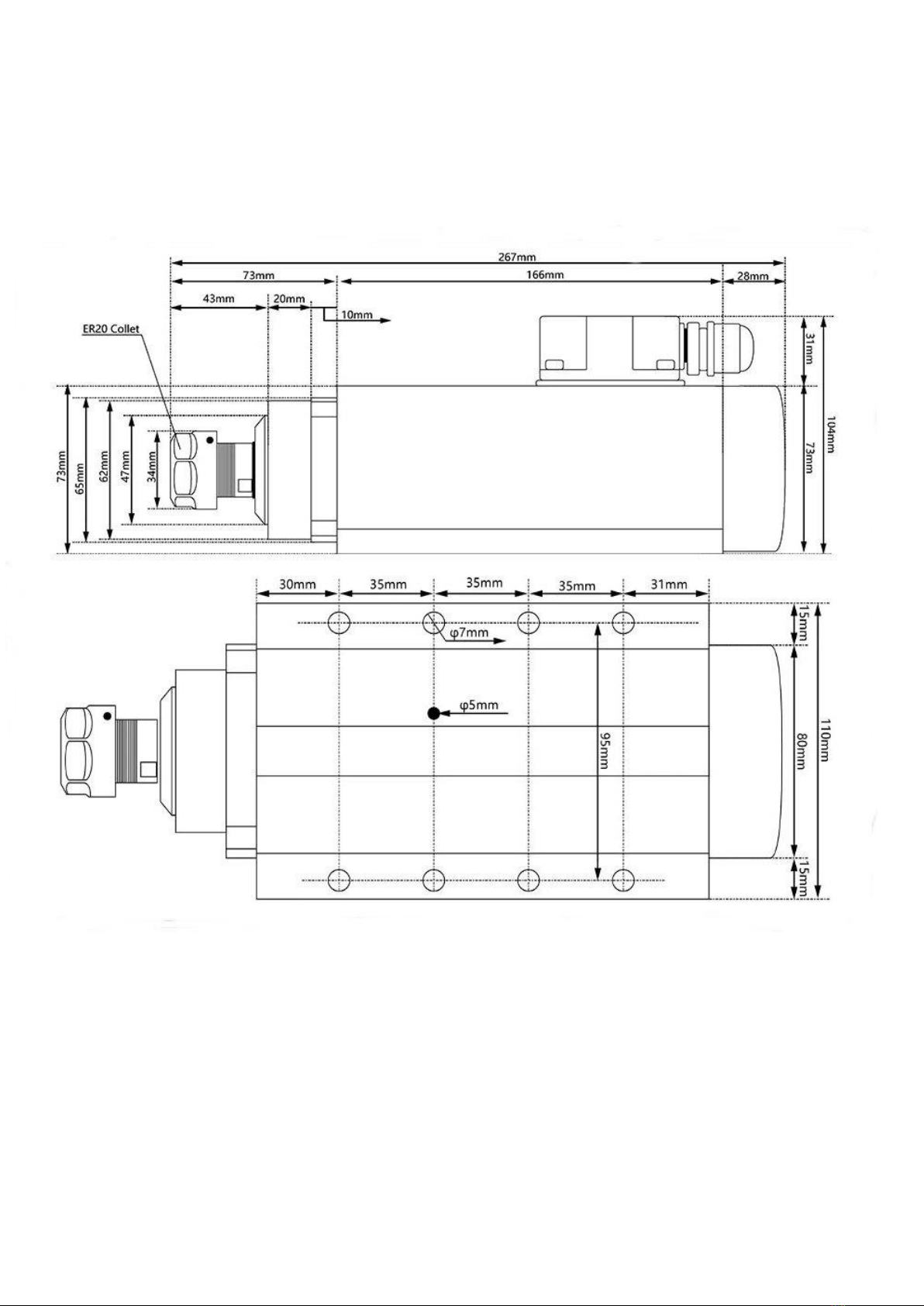
•Spindle Power –2.2kW
•Spindle Maximum Speed –18,000 rpm
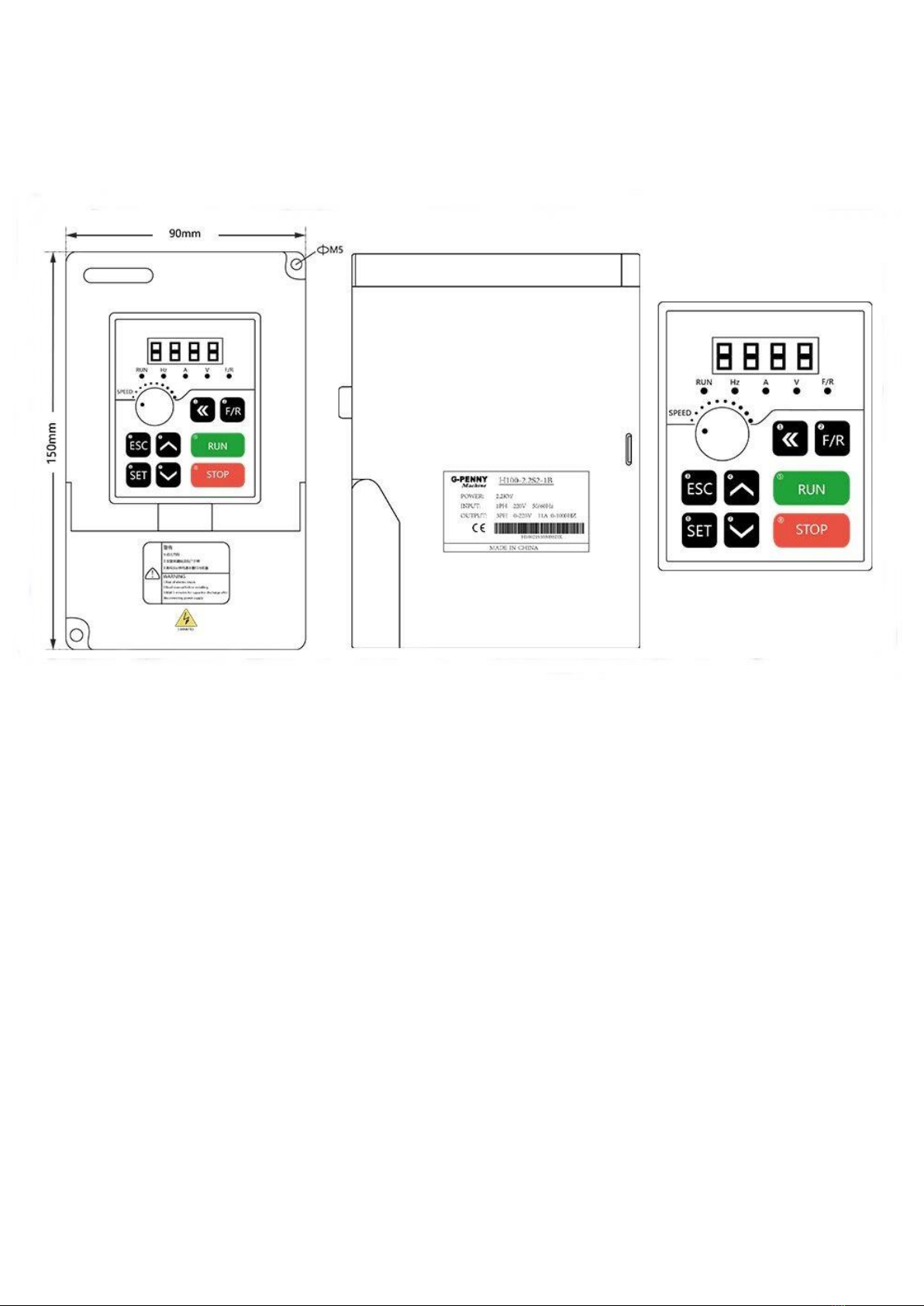
•VFD Supply Voltage –230V AC
•VFD Maximum Current –9.5A
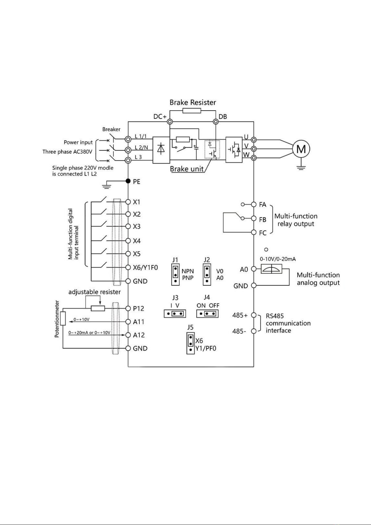
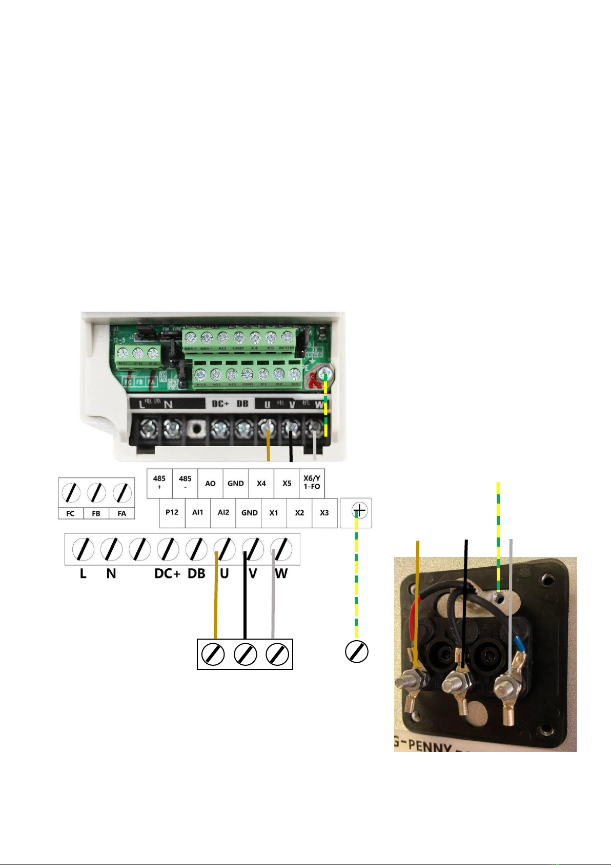
This document is designed to give an overview of the wiring options for the aircooled ER20 spindle
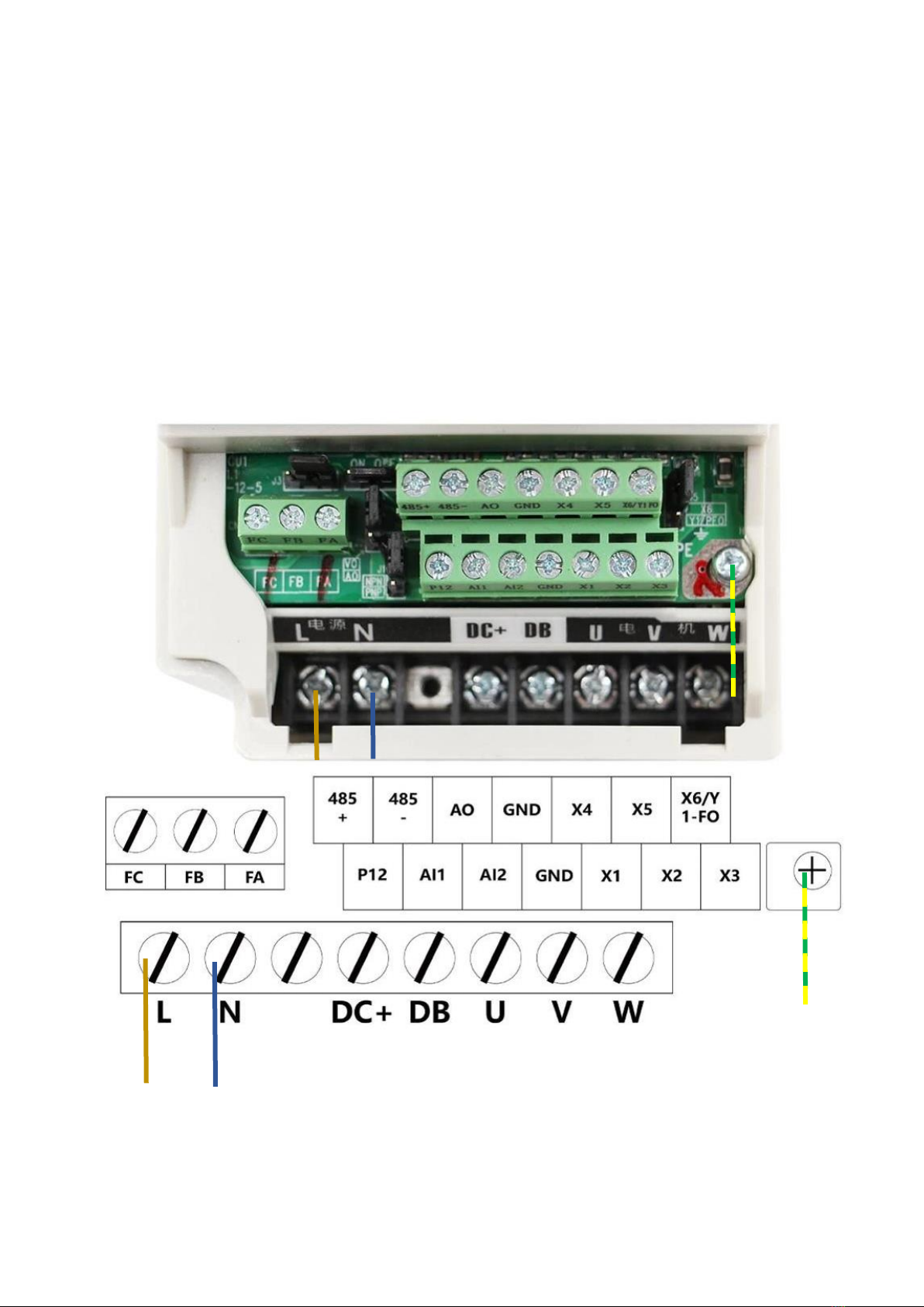
and H100 VFD products. The H100 VFD accepts several input / control wiring set ups, but only those
commonly used in CNC applications will be discussed here.
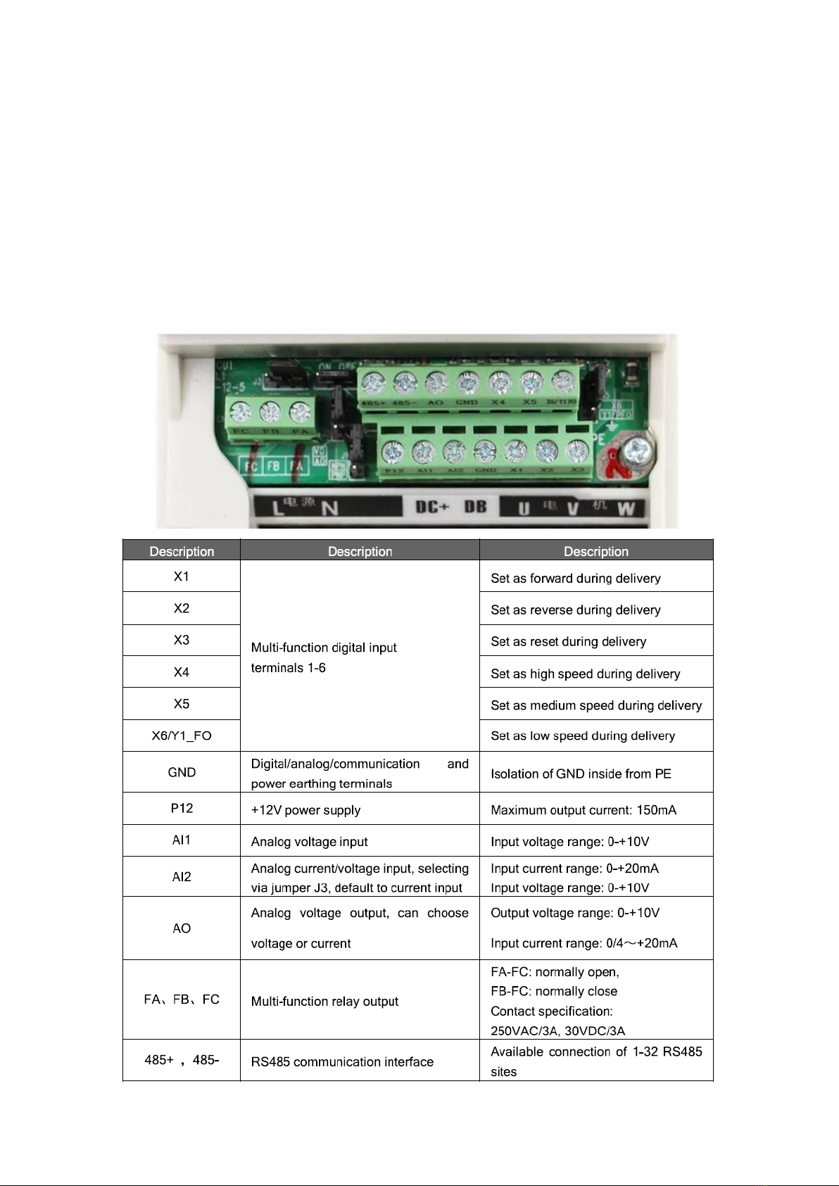
There is a factory supplied user manual for the H100 VFD. It is available for download HERE. Please
familiarise yourself with this document as it contains much technical information that will not be
covered in this document.
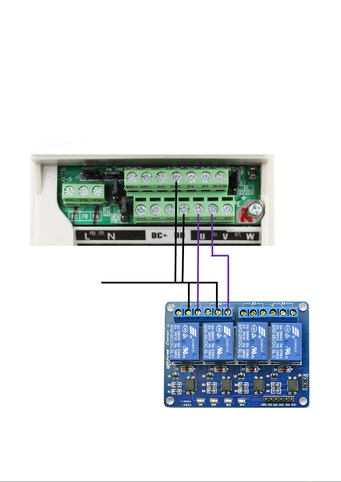
Software setting examples are given for Mach 3 only, but other CNC software will also work with the
board.

Page 3of 16
Version 1.0 –June 2021

Page 4of 16
Version 1.0 –June 2021

Page 5of 16
Version 1.0 –June 2021

Page 6of 16
Version 1.0 –June 2021
Start by wiring the drive for 230V power supply. Note that the protective earth (PE) is located away
from the input terminals to the right of the control terminal group. The diagrams below show both
the actual ‘as photographed’VFD connection area, and also the labelled schematic view.
230V AC Phase
230V AC Neutral
230V AC Earth

Page 7of 16
Version 1.0 –June 2021
Next wire the spindle to the VFD. Again, note that the protective earth (PE) is located away from the
input terminals to the right of the control terminal group. The diagrams below show both the actual
‘as photographed’ VFD connection area, and also the labelled schematic view.
Use appropriate shielded 3C+E VFD rated flexible cord for this connection. The shielding should be
connected to chassis ground at the control cabinet end only.

Page 8of 16
Version 1.0 –June 2021
Only change the jumper settings of the drive with the power off! Changing with power connected
can damage the drive.
The H100 VFD comes with a series of PCB mounted jumpers. These are used to set various functional
parameters on the board. If they are not set correctly, you may not get the behaviour from the
inverter you expect! For the wiring set up we will cover below, you will want to set the jumpers as
per the schematic.
If you need any further information on jumper settings, please refer to page 13 (section 3.5) of the
H100 user manual.

Page 9of 16
Version 1.0 –June 2021
The green screw terminals of the inverter are used for the logic level input / output control between
this device and your machine controller. Note that each terminal is labelled, and a description and
default setting can be found in the table below.
Please make sure to conncet both “GND”terminals back into the common DC bus of your machine
controller, or else you will not get proper communication between devices.
For the parameters required to change these default settings, please see page 22 of the H100 user
manual.

Page 10 of 16
Version 1.0 –June 2021
Terminals X1 (Forward) and X2 (Reverse) need to be wired to be switched remotely if you wish them
to be controlled by Mach 3 and your CNC controller. The example below shows these terminals
being switched via our 5V relay module, but any other relay or 12-24v DC transistor based control
will work.
The relay module is normally open. When it is activated via the CNC control, it connects the input to
the 0V DC common bus, thus activating the relevant input on the VFD. Releasing the relay will stop
sending the function signal to the VFD. This is an NPN wiring configuration as we are pulling the VFD
terminals down to 0v to send an activation signal to them.
Common 0v DC Bus

Page 11 of 16
Version 1.0 –June 2021
The breakout board supports two options for supplying spindle speed information to your spindle
drive. We will use the 0-10V DC analogue signal as it is the most common method for speed control.
The diagram below shows the typical wiring for the H100 VFD using the 0-10V analogue method. It is
essential that the 0V rail from the VFD and the breakout board are both wired back to the common
DC bus. The 0-10V DC output from your CNC controller is connected into terminal A12. No other
connections are needed.
0V DC Common Rail
0-10V Analogue Out

Page 12 of 16
Version 1.0 –June 2021
The rest of this manual assumes that you have your CNC controller set up and talking to your PC
already. If not, go away now and get this working (see our Breakout Board user manuals for a
detailed guide). The spindle control should be the last part of your project.
This section picks up from the breakout board user manual at section 6.5.
Now open the “Spindle Setup” tab and make sure that the “Disable Spindle Relays” box is
UNCHECKED. You need to set the Clockwise (M3) Output number to #1 (or whichever number
output you set just before), and CCW (M4) to output #2 (or whichever output number you set up
before).
Mach3 will only allow you to use outputs 1-6 for spindle relay control. We suggest always using #1
for CW, #2 for CCW, and #3 & #4 for mist and flood coolant respectively.

Page 13 of 16
Version 1.0 –June 2021
In the Motor Outputs tab, you need to enable the spindle, set the Step Pin#, Dir Pin#, Step Port & Dir
Port all to 1. Click on Apply again to save!
Next return to the Spindle Setup tab and enter the details below. If your VFD needs a higher than 0V
minimum setting then adjust the minimum PWM setting up by 10% per volt required. For most
VFD’s however (the H100 included) 0% will be perfect.

Page 14 of 16
Version 1.0 –June 2021
You will now need to configure your spindle pulleys to match
the hardware on your machine. Find this via Config -> Spindle
Pulleys.. as shown to the right.
Leave the box set as Pulley Number 4 (Mach 3 doesn’t like it if
you change) and then set the minimum and maximum speeds
to match those that your VFD supports. This number is the
RPM (Revolutions per minute) that you are limited to. For this
example, the H100 will use 4,000 as its minimum and 18,000
as its maximum, as it must be running at least 4,000RPM, but
no more than 18,000RPM.
Click OK to save your settings.

Page 15 of 16
Version 1.0 –June 2021
Finally, we need to set the VFD to work with external control,
and with the spindle motor we are using. Below is the
manufacturer recommended sequence for doing this. Please
note that doing this out of order can cause problems later. If
you would like to change any other settings, please refer to the
H100 user manual.
We will mostly be using the push buttons on the front of the
inverter to change settings. The button functions are:
SET –Used to ‘enter’a setting for adjustment
ESC –Backs up one level
UP / DOWN arrows –Used to navigate through a menu, or to
change a variable up / down
SHIFT arrow –Used to move the cursor to the left so you can
change other digits of a parameter
The correct basic parameters for CNC control with this spindle are:
F013=8 –This resets the inverter to factory default
F005=300 –Sets the maximum frequency of the drive. 300Hz is 18kRPM, 400Hz is 24kRPM with this
spindle
F004=300 –Sets the reference frequency of the drive. 300Hz is 18kRPM, 400Hz is 24kRPM with this
spindle
F003=300 –Sets the main frequency of the drive. 300Hz is 18kRPM, 400Hz is 24kRPM with this
spindle
F072=300 –Sets the high end frequency that corresponds to 10V on the analogue input
F070=000 –Sets the potentiometer input for voltage, 0-10V range
F002=004 –Sets the VFD to look for speed control information form the AI12 terminal
F001=001 –Sets the VFD to look for forward / reverse signals from the X1 & X2 terminals
Please read through the H100 user manual from page 35 for a detailed description of all the
available parameters. There are several cool features that you may wish to make use of that have
not been covered here.

Page 16 of 16
Version 1.0 –June 2021
www.vikingmachinery.co.nz
https://www.trademe.co.nz/Members/Listings.aspx?member=4906214
https://www.instagram.com/james_viking_machinery/
https://www.thingiverse.com/VikingNZ/about
https://www.youtube.com/channel/UCgnl_7dUO9MeNOyI_jWO5QQ?view_as=subscriber
https://grabcad.com/james.hussey-3
http://www.machsupport.com/wp-content/uploads/2013/04/Mach3Version3.043.066.exe
http://www.machsupport.com/wp-content/uploads/2013/02/Mach3Mill_Install_Config.pdf
https://github.com/Viking-
Machinery/Viking_User_Manuals/blob/master/H100%20VFD%20User%20Manual.pdf
This manual suits for next models
1
Popular DC Drive manuals by other brands

Rockwell Automation
Rockwell Automation Allen-Bradley PowerFlex 755 installation instructions

G-U
G-U ELTRAL S60 Assembly and operating instructions

Seagate
Seagate Decathlon 850 installation guide

Wittenstein Alpha
Wittenstein Alpha VDT+ Series operating manual

Lenze
Lenze 9300 Series manual

Becker
Becker EVO 20 R Assembly and operating instructions