Table of Contents
Warnings and Important Information
Bottom Mount
Dimensions (36”)
Specifications (36”)
Cutout Dimensions (36”)
Anti-Tip Dimensions (36”)
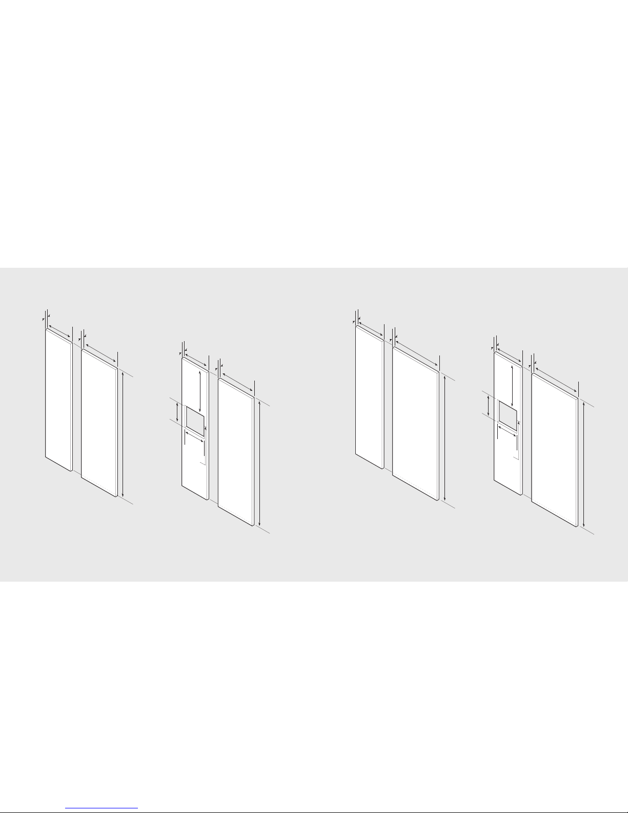
Overlay Dimensions (36”)
Custom Grille Dimensions (36”)
Custom Grille Dimensions (Dual 36”)
Side-By-Side
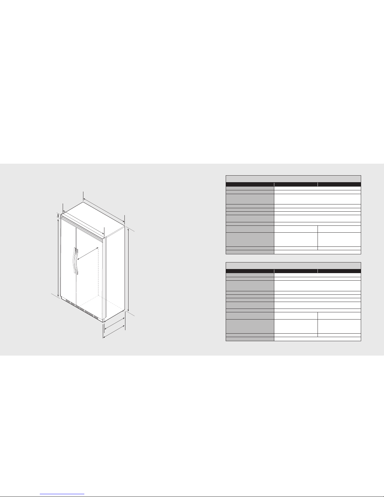
Dimensions (42”)
Dimensions (48”)
Specifications (42”and 48”)
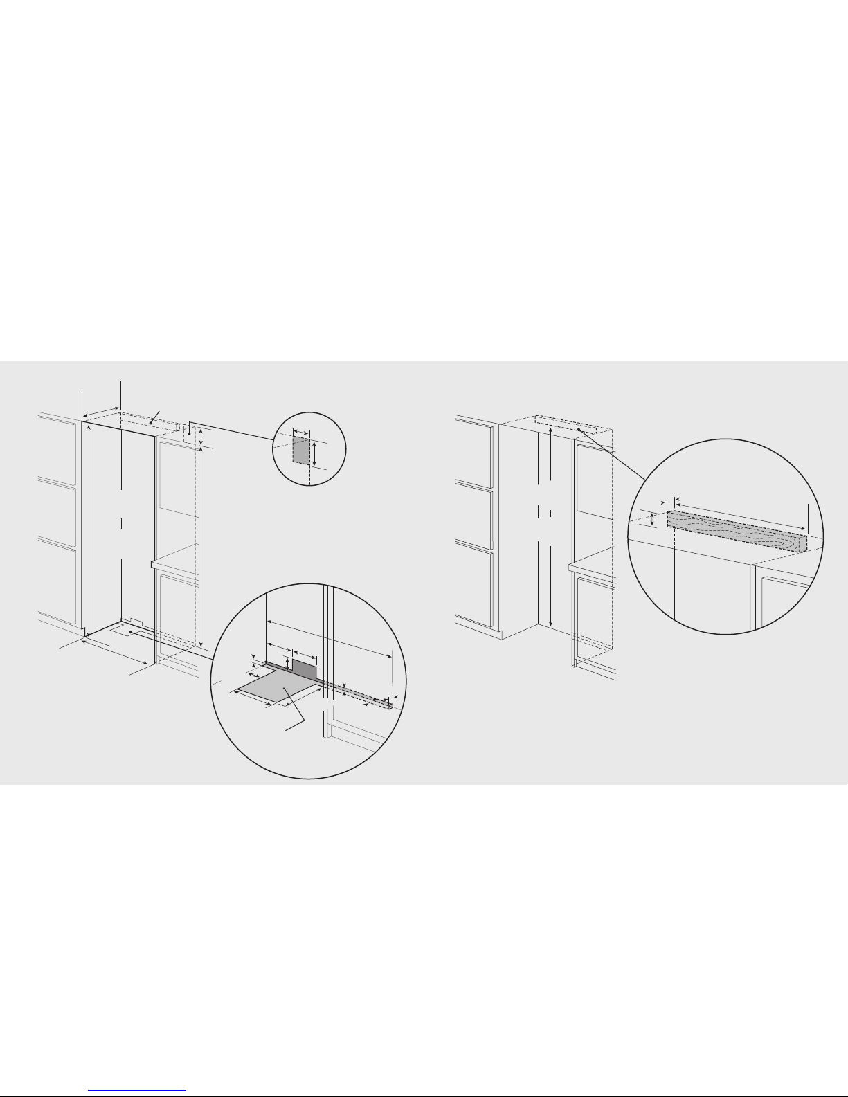
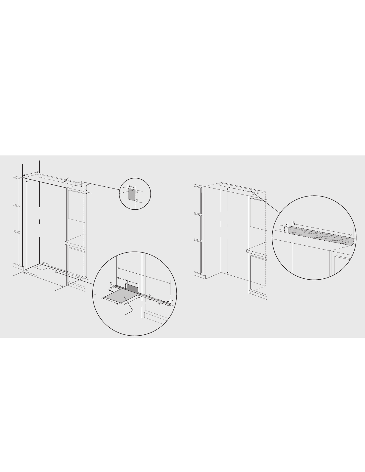
Cutout Dimensions (42”)
Anti-Tip Dimensions (42”)
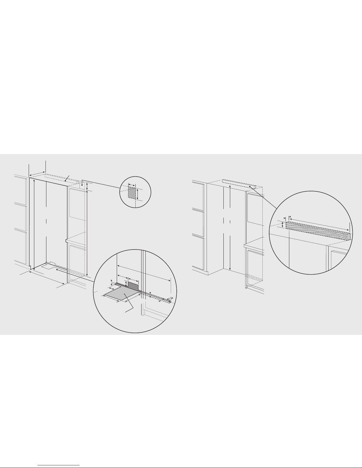
Cutout Dimensions (48”)
Anti-Tip Dimensions (48”)
Overlay Dimensions (42”)
Overlay Dimensions (48”)
Custom Grille Dimensions (42”)
Custom Grille Dimensions (48”)
All Refrigerator/Freezer
Dimensions (30”and 36”)
Specifications (30”and 36”)
Cutout Dimensions (30”)
Anti-Tip Dimensions (30”)
Cutout Dimensions (36”)
Anti-Tip Dimensions (36”)
Dimensions (Dual 30”)
Dimensions (Dual 30”and 36”)
Dimensions (Dual 36”and 36”)
Specifications (Dual)
Cutout Dimensions (Dual 30”)
Anti-Tip Dimensions (Dual 30”)
Cutout Dimensions (Dual 30”and 36”)
Anti-Tip Dimensions (Dual 30”and 36”)
Cutout Dimensions (Dual 36”)
Anti-Tip Dimensions (Dual 36”)
Overlay Dimensions (30”and 36”)
Custom Grille Dimensions (30”)
Custom Grille Dimensions (36”)
Custom Grille Dimensions (Dual 30”)
Custom Grille Dimensions (Dual 30”and 36”)
Custom Grille Dimensions (Dual 36”)
Cabinet Information
Custom Side Panel Dimensions
Custom Panel General Information
Ice and Water Dispenser Bezel Removal
Custom Door Panel Installation–Refrigerator
Custom Door Panel Installation–Freezer
Ice and Water Dispenser Bezel Installation
Custom Panel Hinge Cutout
Custom Grille Installation
General Information
Unpacking & Moving
Installation
Hinge Adjustment
Kickplate Installation
Door Stop Adjustment
Water Filter Installation
Water Filter System Specifications
Final Installation
Performance Checklist
Control Panels
Service & Registration
2
2
3
4
5
6
7
8
9
10
11
12
13
14
15
16
17
18
19
20
21
22
23
24
25
26
27
28
29
30
31
32
33
34
35
36
37
38
39
40
41
42
43
46
46
48
49
50
52
53
55
57
58
59
61
62
63
64
65
66
67
69
IMPORTANT–Please Read and Follow
Make sure that incoming voltage is the same
as unit rating. An electric rating plate
specifying voltage, frequency, wattage,
amperage, and phase is attached to the
product.
To reduce the risk of fire, electrical shock, or
injury to persons, installation work and
electrical wiring must be done by qualified
people in accordance with all applicable
codes and standards, including fire-rated
construction.
The installer should leave these instructions
with the consumer who should retain them for
local inspector’s use and for future reference.
It is your responsibility to:
Comply with installation specifications and
dimensions.
Properly install unit.
Remove any moldings or decorative panels
that prevent the unit from being serviced.
Make sure that you have these materials (not
provided with your unit), which are necessary
for proper installation:
1/4” (6 mm) copper tubing with shutoff
valve
6– #8 x 3” (7.6 cm) wood screws (longer
screws may be required)
1– Saddle valve (do not use self-piercing
feature of the valve)
Assure that floor will support unit, door
panels and contents (approximately 1200
pounds [540 kg]).
Provide a properly grounded electrical outlet.
Assure that location will permit appliance
doors to open a minimum of 90˚.
W A R N I N G
TIP OVER HAZARD
Appliance is top heavy
and tips easily when not
completely installed.
Keep doors closed until
appliance is completely installed and
secured per installation instructions.
Use two or more people to move and install
appliance. Failure to do so can result in death
or serious injury.
ELECTRICAL SHOCK HAZARD
Disconnect power or turn
power disconnect switch to
OFF position before removing
top grille. Failure to do so can
result in death or electric shock.
Your safety and the safety of others is
very important.
We have provided many important safety
messages in this manual and on your
appliance. Always read and obey all
safety messages.
This is the safety alert symbol. This
symbol alerts to hazards that can
result in injury or death to you and
others.
All safety messages will be preceded by the
safety alert symbol and the word“DANGER”
or “WARNING.” These words mean:
Failure to follow these instructions can
result in serious injury or death.
Failure to follow these instructions can
result in serious injury or death.
All safety messages will identify the
hazard, tell you how to reduce the chance
of injury, and tell you what can happen if
the instructions are not followed.
Most of the unit’s weight is at the top. Extra care is needed when moving the unit to prevent tipping.
Use cardboard shipping material or plywood under unit until it is installed in the operating position
to protect floor surface.
D A N G E R
W A R N I N G
WARNING
45