manuals.online logo
Brands
  1. Home
  2. •
  3. Brands
  4. •
  5. Viking
  6. •
  7. Freezer
  8. •
  9. Viking Designer DDFB304 User manual

Viking Designer DDFB304 User manual

Viking Installation Guide
Viking Range Corporation
111 Front Street
Greenwood, Mississippi 38930 USA
Freestanding Bottom-Mount/
French Door Bottom-Mount
Refrigerator/Freezer
Listed
2
IIMMPPOORRTTAANNTTSSAAFFEETTYYIINNSSTTRRUUCCTTIIOONNSS
YYoouurrssaaffeettyyaannddtthheessaaffeettyyooffootthheerrssiissvveerryyiimmppoorrttaanntt..
We have provided many important safety messages in this manual and on your appliance. Always read and obey all safety messages.
This is the safety alert symbol. This symbol alerts you to hazards that can kill or hurt you and others. All safety messages will be
preceded by the safety alert symbol and the word “DANGER” , “WARNING” or “CAUTION”.
These words mean:
All safety messages will identify the hazard, tell you how to reduce the chance of injury, and tell you what can happen if the instructions
are not followed.
Immediate hazards which WWIILLLLresult in severe personal injury or death
Hazards or unsafe practices which CCOOUULLDDresult in severe personal injury or death.
DANGER
WARNING
To reduce the risk of fire, electric shock, serious injury or death when using your refrigerator, follow these basic
precautions, including the following:
Hazards or unsafe practices which CCOOUULLDDresult in minor personal injury or property damage.
CAUTION
WARNING
•Read all instructions before using the refrigerator.
•Observe all local codes and ordinances. Install refrigerator according to Installation Instructions. All connections for
water, electrical power and grounding must comply with local codes and be made by licensed personnel when
required.
•Do not modify plug on power cord. If plug does not fit electrical outlet, have proper outlet installed by a qualified
technician. Replace worn power cords and/or loose plugs.
•Do not ground to a gas line or cold-water pipe.
•Do not remove warning tag from power cord
•Refrigerator is designed to operate on a separate 115 volt, 15 amp., 60 cycle line.
•Do not tamper with refrigerator controls.
•Do not service or replace any part of refrigerator unless specifically recommended in Use & Care or Installation
Instructions. Do not attempt service if instructions are not understood or if they are beyond personal skill level.
•Always disconnect refrigerator from electrical supply before attempting to change light bulbs, clean, or service the
refrigerator. Disconnect the power cord by grasping the plug, not the cord.
•Always read and follow manufacturer’s storage and ideal environment instructions for items being stored in refrigerator.
•Never allow children to operate, play with, crawl inside or stand on any part the refrigerator.
•Never clean refrigerator parts with flammable fluids. The fumes can create a fire hazard or explosion.
•Clean up spills or water leakage associated with water installation.
•Keep your refrigerator in good condition. Bumping or dropping refrigerator can damage refrigerator or cause
refrigerator to malfunction or leak. If damage occurs, have refrigerator checked by qualified service technician.
--SSAAVVEETTHHEESSEEIINNSSTTRRUUCCTTIIOONNSS--
GGEENNEERRAALLIINNFFOORRMMAATTIIOONN
IIMMPPOORRTTAANNTT--PPLLEEAASSEERREEAADDAANNDDFFOOLLLLOOWW
Make sure that incoming voltage is the same as unit rating. An electric rating plate specifying voltage, frequency, and
amperage is attached to the product.
To reduce the risk of fire, electric shock, or injury to persons, installation work and electrical wiring must be done by qualified
people in accordance with all applicable codes and standards, including fire-rated construction.
The installer should leave these instructions with the consumer who should retain them for local inspector’s use and for
future reference.
3
BBAASSIICCSSPPEECCIIFFIICCAATTIIOONNSSAANNDDDDIIMMEENNSSIIOONNSS
FFrreeeessttaannddiinnggBBoottttoommMMoouunntt//FFrreenncchhDDoooorrBBoottttoommMMoouunntt
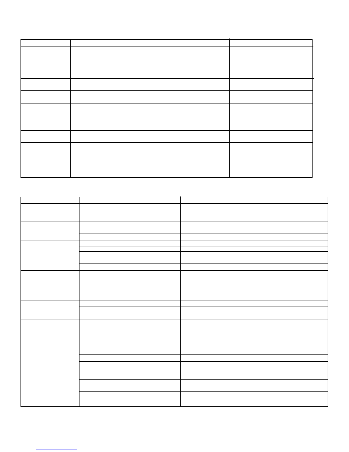
DDEESSCCRRIIPPTTIIOONNVVCC//DDDDBBFF//VVCC//DDDDFFFF
Overall Width 35 5/8” (90.5 cm)
Addition of side panels: 35 7/8” (91.1 cm)
Overall Height from Bottom 70 1/8” (178.1 cm)
Addition of tops/grilles: 71 7/8” (182.6 cm)
Overall Depth from Rear To front of door: 26 3/4” (67.9 cm)
Cutout Width 36” (91.4 cm)
Cutout Height 70 1/2” (179.0 cm)
Addition of tops/grilles 72” (182.9 cm)
Cutout Depth 24” (61.0 cm)
Electrical Requirements 115 volt, 60 Hz, 15 amp dedicated circuit; 3-wire cord with grounded 3-prong
plug attached to product.
Maximum Amp Usage 7.9 amps
Inlet Water Requirements 1/4” copper tubing inlet waterline; minimum 35 psi; maximum 100 psi
Overall Interior Capacities Bottom Mount French Door Bottom Mount
•Refrigerator 14.4 cu. ft. (407 liters) 14.1 cu. ft. (399 liters)
•Freezer 5.5 cu. ft. (156 liters) 5.5 cu. ft. (156 liters)
•Total Capacity 19.9 cu. ft. (563 liters) 19.6 cu. ft. (555 liters)
Approximate Shipping Weight 327 lbs. (148.7 kg)
DANGER
RRiisskkooffCChhiillddEEnnttrraappmmeenntt
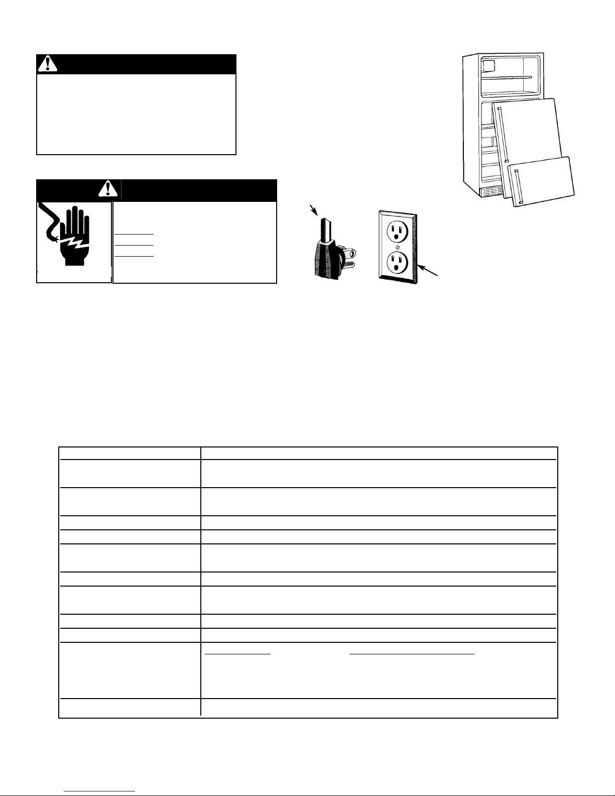
BBEEFFOORREEYYOOUUTTHHRROOWWAAWWAAYYYYOOUURROOLLDD
RREEFFRRIIGGEERRAATTOORROORRFFRREEEEZZEERR::
•Take off the doors.
•Leave the shelves in place so that children
may not easily climb inside.
IIMMPPOORRTTAANNTT::Child entrapment and
suffocation are not problems of the past.
Junked or abandoned refrigerators are still
dangerous... even if they will sit for “just a few
days.”
IIttiisstthheeccuussttoommeerr’’ssrreessppoonnssiibbiilliittyyttoo::
•contact a qualified electrical installer.
•assure that the electrical installation is adequate and in conformance with the National Electrical Code, ANSI/NFPA
70-latest edition or Canadian Electrical Code C22.1-1998 and C22.2 No. 0-M91 (or latest edition), and all local codes
and ordinances. (115 volt, 60-Hz, 15 amp, fused, electrical supply is required. It is required that a separate circuit
serving only this appliance be provided. This appliance is equipped with a power supply cord having a 3-prong
grounding plug. To minimize possible shock hazard, the cord must be plugged into a mating 3-prong, grounding-
type wall receptacle. If a 2-prong receptacle is encountered, the customer must contact a qualified electrical installer
to have it replaced with a properly grounded 3-prong receptacle. Do not use an extension cord or adapter plug.)
EELLEECCTTRRIICCAALLSSHHOOCCKKHHAAZZAARRDD
PPlluuggiinnttooaaggrroouunnddeedd33--pprroonnggoouuttlleett..
DDOONNOOTTrreemmoovveeggrroouunnddpplluugg..
DDOONNOOTTuusseeaannaaddaapptteerr..
DDOONNOOTTuusseeaanneexxtteennssiioonnccoorrdd..
FFaaiilluurreettooffoolllloowwtthheesseeiinnssttrruuccttiioonnss
ccoouullddrreessuullttiinnffiirreeoorreelleeccttrriiccaallsshhoocckk..
WARNING
Power cord with 3-prong
grounding plug
Grounding-type wall
receptacle
**WWhheenniinnssttaalllliinnggiinnttooaaccuuttoouutt,,tthheeeeddggeeoofftthheeddoooorrmmuussttbbee2277//88””((77..33ccmm))ffrroommtthheeaaddjjaacceennttccoouunntteerrttooppccaabbiinneett..
4
IINNSSTTAALLLLAATTIIOONN
Your refrigerator was packed carefully for shipment. Remove and discard all packaging and tape. Do not remove the
model/serial number label.
LLooccaattiioonn
•Do not install refrigerator near oven, radiator or other heat source. If not possible, shield refrigerator with cabinet
material.
•Do not install where the temperature falls below 55oF (13oC) or rises above 110oF (43oC). Malfunction may occur at
these temperatures.
•Refrigerator is designed for indoor household application only.
MMeeaassuurriinnggtthheeOOppeenniinngg
When installing your refrigerator, measure carefully. Allow 1/2” (1.3 cm) space at top and 1/2” (1.3 cm) behind the
machine compartment cover (located in the rear) for proper air circulation. Sub-flooring or floor coverings (i.e. carpet,
tile, wood floors, rugs) may make your opening smaller than anticipated. Some clearance may be gained by using the
leveling procedure under “LEVELING”.
TTrraannssppoorrttiinnggYYoouurrRReeffrriiggeerraattoorr
•NNEEVVEERRtransport refrigerator on its side. If an upright position is not possible, lay refrigerator on its back. Allow
refrigerator to sit upright for approximately 30 minutes before plugging it in to assure oil returns to the compressor.
Plugging the refrigerator in immediately may cause damage to internal parts.
•Use an appliance dolly when moving refrigerator. AALLWWAAYYSStruck refrigerator from its side or back - NNEEVVEERRfrom its
front.
•Protect outside finish of refrigerator during transport by wrapping cabinet in blankets or inserting padding between
the refrigerator and dolly.
•Secure refrigerator to dolly firmly with straps or bungee cords. Thread straps through handles when possible. Do not
overtighten. Overtightening restraints may dent or damage outside finish.
DDoooorraannddDDrraawweerrRReemmoovvaall
Some installations require door/drawer removal to transport the refrigerator to its final location.
DANGER
To avoid electrical shock which can cause severe personal injury or
death, observe the following:
•Disconnect power to refrigerator before removing doors or drawer.
Connect power only after replacing doors or drawer.
•Green ground wire must be attached to top hinge while performing
door removal and replacement.
•Tape decorative panels (select models) securely into place before
removing door handles.
CAUTION
To avoid damage to walls and flooring observe
the following:
•Protect vinyl or other flooring with cardboard,
rugs or other protective material, prior to
moving refrigerator.
•DDooNNoottadjust refrigerator to be any shorter
than 68 1/2” tall (minus hinge and cap). Doing
so may damage underside components.
BBoottttoommMMoouunnttDDoooorrRReemmoovvaall
1. Unplug power cord from power source.
2. Remove toe grille.
3. Remove top hinge cover from refrigerator door by removing
Phillips screw and retain screw and cover for later use.
4. Unscrew 5/16” hex head screws from top hinge to remove hinge
and retain all screws for later use.
5. Lift refrigerator door from center hinge pin.
6. Remove plastic sleeve, if present.
7. See page 6 for drawer removal instructions
5
FFrreenncchh--DDoooorrBBoottttoommMMoouunnttDDoooorrRReemmoovvaall
1. Unplug power cord from power source.
2. Remove toe grille.
3. Remove top hinge covers from refrigerator
doors by removing Phillips screw and retain
screw and cover for later use.
4. Unscrew 5/16” hex head screws from top hinge
to remove hinge and retain all screws for later
use.
5. Lift right side refrigerator door from center hinge
pin. Remove door closure from center hinge pin
on the right side and retain for later use.
6. Disconnect wire harness on top of left side
refrigerator door top hinge. Release two-pin
connector by pressing junction point with a flat
blade screwdriver or fingernail. Green ground
wire remains attached to the hinge.
7. Unscrew 5/16” hex head screws from top
hinge to remove hinge and retain all screws
for later use. Lift left side refrigerator door,
along with top hinge, from center hinge pin.
8. Remove phillips screws to remove right and
left hinges and retain
all screws for later
use.
Right
side
door
closure
IINNSSTTAALLLLAATTIIOONN
PPuulllloouuttFFrreeeezzeerrDDrraawweerrRReemmoovvaall
DANGER
To prevent accidental child entrapment or suffocation risk,
do not remove the divider in the top freezer basket.
CAUTION
To avoid possible injury, product, or property damage,
you will need two people to perform the following
instructions.
1. Pull drawer open to full extension.
2. Tilt the lower basket forward and lift to remove.
3. Lift top of drawer front to unhook the drawer
from the slides. Lift door front out to remove
6
1. Pull both rails out to full extension.
2. While supporting door front, hook supports into slots
located on inside of each slide.
3. Lower door front into final position.
4. Place the basket cradles back onto the drawer slides.
5. Tilt the lower basket front down and set it down into the
basket cradles.
IINNSSTTAALLLLAATTIIOONN
NNOOTTEE::All four drawer
bracket supports must
be in the proper slots
for the drawer to
function properly.
PPuulllloouuttFFrreeeezzeerrDDrraawweerrRReeiinnssttaallllaattiioonn
BBoottttoommMMoouunnttDDoooorrRReeiinnssttaallllaattiioonn
Install hinge assemblies
1. Install top hinge loosely with 5/16” hex head screws.
2. Install center hinge with phillips screws.
3. Place hinge side of refrigerator door on center hinge pin.
4. While holding refrigerator door upright, tighten down top hinge with 5/16” hex head driver and replace hinge cover.
FFrreenncchh--DDoooorrBBoottttoommMMoouunnttDDoooorrRReeiinnssttaallllaattiioonn
1. Install hinge assemblies. Install center hinge with phillips screws.
2. Place hinge side of refrigerator door on center hinge pin. Install top hinge with
5/16” hex head screws.
3. While holding refrigerator door upright, tighten down top hinge with 5/16” hex
head driver.
4. Reconnect two-pin connector.
5. Replace top hinge covers.
7
IINNSSTTAALLLLAATTIIOONN
OOppeenniinnggaannddCClloossiinnggtthheeRReeffrriiggeerraattoorrDDoooorrss--FFrreenncchh--DDoooorrBBoottttoommMMoouunnttMMooddeellss
CCoonnnneeccttiinnggtthheeWWaatteerrSSuuppppllyy
Your new refrigerator is uniquely designed with two
refrigerator doors. Either door can be opened or closed
independently of one another. There is a vertically-hinged
section on the left fresh food door. When the left door is
closed, the hinged section automatically forms a seal
between the two doors when both doors are closed. When
the left door is opened, the hinged seal automatically folds
inward so that it is out of the way.
WARNING
To avoid electrical shock which can cause severe personal
injury or death, DDOONNOOTTattempt to remove the hinged
seal from the fresh food section.
CAUTION
To avoid possible product damage, AALLWWAAYYSSverify that
the hinged seal is folded against the edge of the door
prior to closing.
WARNING
To reduce the risk of injury or death, follow basic
precautions including the following:
•Do not attempt installation if instructions are not
understood or if they are beyond personal skill level.
•Do not service ice maker
•Observe all local codes and ordinances.
•Water damage due to an improper water connection
may cause mold/mildew growth. Clean up spills or
leakage immediately.
CAUTION
To avoid property damage or possible injury, follow basic
precautions, including the following:
•Consult a plumber to connect 1/4” OO..DD..ccooppppeerrttuubbiinnggto
household plumbing to assure compliance with local codes
and ordinances.
•Confirm water pressure to water valve is between 35 and 100
pounds per square inch, 20 pounds per square inch without
a filter.
•Do not use a self-piercing, or 3/16” saddle valve. Both
reduce water flow, can become clogged over time, and may
cause leaks if repair is attempted.
•Tighten nuts by hand to prevent cross threading. Finish
tightening nuts with pliers and wrenches. DO NOT
overtighten.
•Wait two to three hours before placing refrigerator into final
position to check and correct any water leaks. Recheck for
leaks after 24 hours.
•Verify the copper tubing under the sleeve is smooth and free
from defects. Do not reuse an old sleeve
MMaatteerriiaallssNNeeeeddeedd
•1/4” outer diameter flexible copper tubing
•Shut-off valve (requires a 1/4” hole to be drilled into
water supply line before valve attachment)
•(2) Adjustable wrenches
•1/4” hex nut driver
NNOOTTEE::
•Use copper tubing only for installation. Plastic is less durable and can cause damage.
•Add 8 feet to tubing length needed to reach water supply for creation of service loop.
8
CCoonnnneeccttiinnggtthheeWWaatteerrSSuuppppllyy
IINNSSTTAALLLLAATTIIOONN
1. Create service loop with copper tubing ( minimum 2 feet
diameter). Avoid kinks in the copper tubing when
bending the service loop. Do not use plastic tubing. See
figure 1
2. Remove plastic cap from water valve inlet port. See figure
2.
3. Place brass nut (A) and sleeve (B) on copper tube end as
illustrated. RReemmeemmbbeerr::Do not use old sleeve. The nut
and the sleeve are provided in the consumer literature
packet. See figure 3
4. Place end of copper tubing into water valve inlet port.
Shape tubing slightly. Do not kink - so that tubing feeds
straight into inlet port. See figure 4.
5. Slide brass nut over sleeve and screw nut into inlet port.
Place adjustable wrench on nut “1” attached to plastic
waterline and maintain position. Using second adjustable
wrench, turn the lower nut “2” counterclockwise and fully
tighten the upper nut in place. IIMMPPOORRTTAANNTT::Do not
overtighten. Cross threading may occur. See figure 5
6. Pull on tubing to confirm connection is secure. Connect
tubing to frame with tubing clamp (C) and turn on water
supply . See figure 6. Check for leaks and correct if
necessary. Continue to observe the water supply
connection for two or three hours prior to moving the
refrigerator to its permanent location.
7. Monitor water connection for 24 hours. Correct leaks, if
necessary.
Figure 1
Figure 2 Figure 3
Figure 4 Figure 5 Figure 6
CC
2 feet diameter
minimum
BB
BB
AA
11
22
AA
9
CAUTION
To protect property and refrigerator from damage, observe the following:
•Protect vinyl or other flooring with cardboard, rugs, or other protective material.
•Do not use power tools when performing leveling procedure.
To enhance the appearance and maintain performance, the refrigerator should be
level.
NNOOTTEE::Complete any required panel installation and/or water supply connection
before leveling. Refrigerator should be in permanent location prior to leveling.
1. Remove toe grille. Grasp firmly and pull outward to unclip. See figure 7.
2. Using hex head driver, turn the front adjustment screws “A” on each side to
raise or lower the front of the refrigerator.
3. Using the hex head driver, turn each of the adjustment screws “B” to raise or
lower the rear of the refrigerator.
4. Using the carpenter’s level, make sure front of refrigerator is 1/4” (.06 cm) or
approximately 1/2 bubble higher than back of refrigerator and that the
refrigerator is level from side to side.
5. Turn stabilizing legs “C” clockwise until firmly against floor.
6. Turn adjustment screws “A” counterclockwise to allow the full weight of the
refrigerator to rest on the stabilizing legs.
7. Replace the toe grille. Align the toe grille mounting clips with the lower cabinet
slots. Push the toe grille firmly until it snaps into place.
MMaatteerriiaallssNNeeeeddeedd
•3/8” hex head driver
•Carpenter’s level
Figure 7
AABBAA
BB
CC
CC
LLeevveelliinngg
10
SSOOUUNNDD
CClliicckkiinngg
AAiirrrruusshhiinnggoorr
wwhhiirrrriinngg
GGuurrgglliinnggoorr
bbooiilliinnggssoouunndd
TThhuummppiinngg
VViibbrraattiinnggnnooiissee
BBuuzzzziinngg
HHuummmmiinngg
HHiissssiinnggoorr
ppooppppiinngg
PPOOSSSSIIBBLLEECCAAUUSSEE
• Freezer control clicks when starting or stopping compressor.
• Motorized device sounds like an electric clock and snaps in and
out.
• Freezer fan and condenser fan make this noise while operating.
• Evaporator and heat exchanger refrigerant makes this noise
when flowing.
• Ice cubes from ice maker (select models) drop into ice bucket.
• Compressor makes a pulsating sound while running.
• Refrigerator is not level.
• Ice maker water valve hookup (select models) buzzes when ice
maker fills with water.
• Ice maker is in the ‘on’ position without water connection.
• Compressor can make a high-pitched hum while operating.
• Defrost heater hisses, sizzles or pops when operational.
SSOOLLUUTTIIOONN
• Normal operation
• Normal operation
• Normal operation
• Normal operation
• Normal operation
• Normal operation
• See Installation Instructions
for details on how to level
your refrigerator.
• Normal operation
• Stop sound by raising ice
maker arm to OFF position
• Normal operation
• Normal operation
OOPPEERRAATTIINNGGSSOOUUNNDDSS
PPrroobblleemmPPoossssiibblleeCCaauusseeWWhhaattTTooDDoo
Freezer control and lights Refrigerator is in defrost mode. Normal operation. Wait 40 minutes to see if compressor restarts.
are on, but compressor
is not operating
Temperature-controlled Control settings are too low. See use and care manual to adjust controls.
drawers are too warm Freezer controls are set too low. See use and care manual to adjust controls.
Drawer is improperly positioned. See use and care manual to verify drawer positioning.
Refrigerator does not Refrigerator is not plugged in. Plug in refrigerator.
operate Touch temperature controls are set to “OFF”. See use and care manual to set controls.
Fuse is blown or circuit breaker needs to Replace any blown fuses.
be reset. Check circuit breaker and reset, if necessary.
Power outage has occurred . Call local power company to report outage.
Refrigerator still will not Refrigerator is malfunctiong . Unplug refrigerator and
operate transfer food to another refrigerator. If another refrigerator is not
available, place dry ice in freezer section to preserve food.
Warranty does not cover food loss. Contact service for
assistance.
Food temperature Condenser coils are dirty. Clean coils according to use and care manual.
is too cold Refrigerator or freezer controls are set too Properly adjust controls.
high.
Food temperature is too Door is not closing properly. Check for internal obstructions that are keeping door from is too
warm closing properly.
Refrigerator is not level.
See installation instructions for details on how to level your
refrigerator. Check gaskets for proper seal, clean if necessary.
Controls need to be adjusted. See use and care manual to adjust your controls.
Condenser coil is dirty. Clean coils according to use and care manual.
Rear air grille is blocked. Check the positioning of food items in refrigerator to make sure
grille is not blocked. Rear air grilles are located under produce
drawers.
Door has been opened frequently , or has Reduce the time door is open. Organize food items efficiently
been opened for long periods of time. to assure door is open for as short a time as possible.
Food has recently been added. Allow time for recently added food to reach refrigerator or
freezer temperature.
TTrroouubblleesshhoooottiinngg
11
**MMaannuuffaaccttuurreerriissnnoottrreessppoonnssiibblleeffoorrpprrooppeerrttyyddaammaaggeedduueettooiimmpprrooppeerriinnssttaallllaattiioonnoorrwwaatteerrccoonnnneeccttiioonn..
TTrroouubblleesshhoooottiinngg
PPrroobblleemmPPoossssiibblleeCCaauusseeWWhhaattTTooDDoo
Refrigerator has an odor Odor producing foods should be covered. Clean according to instructions in use and care
The interior needs cleaning.
Water droplets form Door gaskets are not sealing properly. Clean gaskets according to instructions in use and care.
outside of door Humidity levels are high. Hot, humid weather can increase condensation.
Controls require adjustment. See use and care to adjust controls.
Water droplets form on Humidity levels are high or door has Reduce time door is open. Organize food items efficiently to
inside of refrigerator been opened frequently. assure door is open for as short a time as possible.
Refrigerator or ice maker Normal operation See operating sounds.
makes unfamiliar sounds
or seems too loud
Temperature-controlled Contents of drawer or positioning of items Reposition food and containers to avoid interference with the
drawers do not in compartments is obstructing drawer. drawers.
close freely Drawer is not in proper position See use and care instructions for proper placement.
Drawer channels are dirty Clean drawer channels with warm, soapy water. Rinse
or need treatment. dry thoroughly. Apply thin layer of petroleum jelly to drawer
channels.
Refrigerator runs too Door has been opened frequently or Reduce time door is open. Organize food items efficiently to
frequently has been opened for long periods of time. assure door is open for shortest time.
Humidity levels too high. Normal operation
Food has recently been added. Allow time for added food to reach refrigerator or freezer
temperature.
Refrigerator is exposed to heat by Evaluate refrigerator’s environment. Refrigerator may need to
environment or appliances nearby. may need to be moved to run more efficiently.
Condenser coils are dirty. Clean coils according to instructions in use and care.
Controls need to be adjusted. See use and care manual to adjust controls.
Door is not closing properly. Check for internal obstructions that are keeping door from
closing properly.
Refrigerator is not level. See installation instructions for details
on how to level your refrigerator. Check gaskets for proper seal,
clean if necessary.
Door gaskets are not sealing properly. See use and care manual for cleaning instructions.
IIcceeaannddWWaatteerr
Ice maker is not Ice maker arm is up Confirm ice maker arm is down. See Automatic Ice Maker
producing ice. instructions in use and care
Water supply is not reaching water valve. See Connecting the Water Supply instructions.
Copper tubing has kinks Turn off water supply and remove kinks. If kinks cannot be
removed, replace tubing.
Water pressure is too low Low water pressure must be between 35 to 100 pounds per
square inch to function properly. A minimum pressure of 35
pounds per square inches recommended for refrigerators with
water filters.
Check freezer temperature See Temperature Controls in use and care manual to adjust
controls. Freezer must be between 0o- 2oF (-18oto -17oC)/
Ice bin is not installed properly See Ice and Water instructions in use and care manual.
Improper water valve was installed. See Connecting the Water Supply instructions. Self-piercing and
3/16” saddle valves cause low water pressure and may clog the
line over time.*
Water filter indicator Water filter needs to be replaced. If filter is not available, replace with bypass filter. See Water
light is red Filter instructions in use and care manual.
Filter indicator sensor needs to be reset See Filter Status Indicator Light in use and care manual.
Refrigerator is leaking Plastic tubing was used for water connection The manufacturer recommends using copper tubing. Plastic
water is less durable and can cause leakage*.
Improper water valve installed Check water connection procedure in installation instructions.
Self piercing and 3/16” saddle valves cause low water pressure
and may clog the line over time.*
12
PPrroobblleemmPPoossssiibblleeCCaauusseeWWhhaattTTooDDoo
Ice forms in inlet Water pressure is low Water pressure must be between 35 - 100 pounds per square
tube to ice maker inch. A minimum pressure of 35 pounds per square inch is
recommended for refrigerators with water filters.
Improper water valve installed. Check water connection procedure in installation instructions.
Self piercing and 3/16” saddle valves cause low water pressure
and may clog the line over time.*
Copper tubing has kinks Turn off water supply and remove kinks. If kinks cannot be
removed, replace tubing.
Saddle valve is not open completely. Open saddle valve completely.
Freezer temperature is too high Adjust freezer controls. Freezer is recommended to be
approximately 0oF (-18oC)/
Water flow is slower than Water pressure is low Water pressure must be between 35 - 100 pounds per square
normal inch. A minimum pressure of 35 pounds per square inch is
recommended for refrigerators with water filters.
. Saddle valve is not open completely. Open saddle valve completely.
Improper water valve installed. Check water connection procedure in installation instructions.
Self piercing and 3/16” saddle valves cause low water pressure
and may clog the line over time.*
Copper tubing has kinks Turn off water supply and remove kinks. If kinks cannot be
removed, replace tubing.
Water filter needs to be changed Change water filter. See use and care manual.
Dispenser water is not Refrigerator has been recently installed. Allow approximately 12 hours for water in holding tank to chill.
cold Water supply in holding tank has been used.
Water appears cloudy Air or bubbles in water. This is normal when first using the dispenser and will disappear
with use.
Particles in water and/or Cabon dust from water filter cartridge Initial water ejected through cartridge may contain harmless
ice cubes carbon dust flushed from cartridge. Will disappear after first few
uses.
Concentration of minerals in water will Particles are not harmful and naturally occur in water supplies.
form particles when water becomes frozen
and melts.
TTrroouubblleesshhoooottiinngg
**MMaannuuffaaccttuurreerriissnnoottrreessppoonnssiibblleeffoorrpprrooppeerrttyyddaammaaggeedduueettooiimmpprrooppeerriinnssttaallllaattiioonnoorrwwaatteerrccoonnnneeccttiioonn..
13
WWIIRRIINNGGDDIIAAGGRRAAMM
FFRREEEESSTTAANNDDIINNGGBBOOTTTTOOMMMMOOUUNNTT//
FFRREENNCCHHDDOOOORRBBOOTTTTOOMMMMOOUUNNTTRREEFFRRIIGGEERRAATTOORR//FFRREEEEZZEERR
13014103 PRINTED IN U.S.A.
HARNESS-CABINET
1
2
3
4
5
6
1
2
3
4
5
6
1
2
3
4
5
6
1
2
3
4
5
6
HARNESS-EVAP/HEATER
7
8
9
7
8
9
YL RD/WH
WATER
DISPENSER
SWITCH
AUTOMATIC
ICEMAKER
DEFROST
HEATER
1
3
4
2
3
2
4
1
GN/YL
BK
TN
WH
FUSE
BK
AMP
CONNECTOR
DEFROST
TERMINATOR
12
BR
12
WH
TN
BK
FAN
SHIELD
GN/YL
OR
FZ THERMISTOR
WH/YL
MOTORIZED
DAMPER
44
33
22
11
1
2
3
4
3
4
HARNESS-MC
BK
GN/YL
GN/YL
YL RD/WH
WH
BK
BR
OR
OR
OR
TN
BR
BK/YL
VT/WH
WH
GN/YL
WH
HARNESS-FF
DAMPER MODULE
YL/RD
BU/RD
WH
GN/YL
YL/BK
RD/WH
RD
REFRIG
LT SW
1
2
3
3
2
1
WH
GN/YL
WH
1
2
3
3
2
1
GN/YL
WH
WH
GN/YL
BU/WH BU/WH BU/WH BU/WH
WH
BU/WH
MULLION
HEATER
HARNESS-REF DOOR
WH/OR
WH WH
WH
VT/WH
GN/YL
BK/YL
BR
TN
OR
OR/BK
WH
RD
GN/YL
VT/WH
YL/RD
BU/RD
WH
GN/YL
WH/BU
WH
RD
GN/YL
BK/GN
RD/BK
YL/BK
5
56
6
WH
RD
GN/YL
BU
WH
BU/WH
L1
L2
BK
BU
CONDENSER
FAN MOTOR
N
L
BK
BASEPAN
WH
BK
GN/YL
WATER
ICE
YL
WH
VT/WH
HARNESS-FZ MODULE
FZ
LT SW
WH
RD RD
CNONC
GN/YL
VT/WH
RD/WH
FZ
LIGHT
VT/WH
LIGHT
HOUSING
GN/YL
WH
BK
BU
YL
1
2
OR
REFRIG
LT SW REFRIG
LIGHT REFRIG
LIGHT
HARNESS-FF CONTROL
LIGHT
HOUSING
YL/BK
RD/BK
WH/BU
WH
RD
GN/YL
BK/GN
RD/BK
DIG GND
OWL
+12
J1
11
22
33
BK/GN
GN/YL
RD/WH
WH
RD/WH
WH
WH
WH
RD
BK/GN
RD/BK
YL/BK
FF
THERMISTOR
DISPLAY
PC BOARD
RD
RD/
WH
BK/GN
YL/WH
WH
TN/WH
TN
WH WH
1
12
23
34
4
1
12
23
34
45
5
OR
MAIN
CONTROLER
PC-BOARD
5
5
6
67
7
TN/WH
8
89
9
J3
J2
1
12
23
34
45
56
67
78
89
9
J1
10
10
RD/BK
VT/WH
RD/WH
OR/BK
YL/BK
WH/BU
WH/YL
WH/OR
BK/GN
WH
BU/RD
YL/RD
BU/WH
BK/YL
BR
BU
RD
YL/WH
BU
YL
RD/WH
BU/WH
VT/WH
BR
TN
BU/RD
YL/RD
BK/YL
RD
BU/WH
YL
RD/WH
VT/WH
BR
BU/RD
YL/RD
BK/YL
BU
RD
OR
TN
OR
BK/GN
RD/BK
WH/OR
WH/BU
YL/BK
OR/BK
WH
WH/OR
BK/GN
RD/BK
WH/BU
YL/BK
WH
WH/YL
OR/BK
WH/YL
GN/YL
WH
WH
SOLENOID
VALVE
HARNESS-MAIN
CONTROLLER
115 VAC
60 HZ
SERVICE
BASEPAN
GROUND
COMP
GROUND
COMP
OVERLOAD
PTCRELAY
BU
RUN
CAP
WH
WH
WH
GN/YL
RIBBED
R
C
S
BUBU
WH
WH
RD/WH
WH/OR
RD/WH
WH/OR
RD/WH
SPLICE
EVAPORATOR
FAN
12
WH BK/YL
BK/YL
WH
ALTERNATEEVAPORATOR
DC FAN CONFIGURATION
1
2
3
4
5
6
7
8
9
EVAPORATORFAN
12
OR/BK BK/GN
OR/BK
BK/GN
GROUND
WIRE NOT
REQUIRED
FORECM
MOTOR
SPLICE
2
3
4
5TN
GN/YL
WH
RD
TN
WH
VT/WH
GN/YL
ALTERNATE
AUTOMATIC
ICEMAKER
1
6
GN/YL
L1
L2
BK
BU
CONDENSER
FAN MOTOR
N
L
BK
BASEPAN
1
2
3
4
5
6
FZ THERMISTOR
WH/YL
AUTOMATIC
ICEMAKER
1
3
4
2
3
2
4
1
GN/YL
BK
TN
WH
FUSE
MOTORIZED
DAMPER
4
3
2
1
1
2
3
4
3
4
N
L
REFRIG
LT SW REFRIG
LIGHT REFRIG
LIGHT
HARNESS-FF CONTROL
LIGHT
HOUSING
HARNESS-CABINET
DEFROST
HEATER
HARNESS-MC
BU
CONDENSER
FAN MOTOR
REFRIG
LT SW REFRIG
LIGHT REFRIG
LIGHT
REFRIG
LT SW REFRIG
LIGHT REFRIG
LIGHT
HARNESS-FF CONTROL
REFRIG
LT SW REFRIG
LIGHT REFRIG
LIGHT
HARNESS-FF CONTROL
EVAPORATOR
FAN
EVAPORATORFAN
SPLICE
SPLICE
115 VAC
60 HZ
SERVICE
L1
L2
1
2
3
RD
RIBBED
WH
BASEPAN
BK
BK
ALTERNATE POWER CORD
All electrical work must be performed by a qualified technician
WARNING
14
15
VIKING RANGE CORPORATION
111 Front Street
Greenwood, Mississippi 38930 USA
(662) 455-1200
For product information
call 1-888-VIKING1 (845-4641)
or visit the Viking Web site at
vikingrange.com
Specifications subject to change without notice
F20395
13040802 (PS0606VR)

Other manuals for Designer DDFB304

2

This manual suits for next models

7

Other Viking Freezer manuals

Viking Quiet Cool VCFB5301 User manual

Viking

Viking Quiet Cool VCFB5301 User manual

Viking Designer DDFB304 User manual

Viking

Viking Designer DDFB304 User manual

Viking Professional DFFB530 User manual

Viking

Viking Professional DFFB530 User manual

Viking VIFB530LSS Assembly instructions

Viking

Viking VIFB530LSS Assembly instructions

Viking Designer DFBB363 User manual

Viking

Viking Designer DFBB363 User manual

Viking DFFB536L Assembly instructions

Viking

Viking DFFB536L Assembly instructions

Viking Designer DDFB364 User manual

Viking

Viking Designer DDFB364 User manual

Viking FDFB5301R Guide

Viking

Viking FDFB5301R Guide

Viking Professional VCFB530 User manual

Viking

Viking Professional VCFB530 User manual

Viking DDFB User manual

Viking

Viking DDFB User manual

Viking DDFB530 Series User manual

Viking

Viking DDFB530 Series User manual

Viking FDFB5301R Assembly instructions

Viking

Viking FDFB5301R Assembly instructions

Viking FDFB5361R Assembly instructions

Viking

Viking FDFB5361R Assembly instructions

Viking DFUR144 User guide

Viking

Viking DFUR144 User guide

Popular Freezer manuals by other brands

AEG ATB8101VNW user manual

AEG

AEG ATB8101VNW user manual

Haier HFZ-136 User instructions

Haier

Haier HFZ-136 User instructions

Zanussi ZBT20420SA user manual

Zanussi

Zanussi ZBT20420SA user manual

Electrolux EUF2744AOW user manual

Electrolux

Electrolux EUF2744AOW user manual

Heinner HFF-N240NFF+ manual

Heinner

Heinner HFF-N240NFF+ manual

Phcbi MDF-MU549DH operating instructions

Phcbi

Phcbi MDF-MU549DH operating instructions

BOMANN KB 7235 instruction manual

BOMANN

BOMANN KB 7235 instruction manual

Haier H3F285 EH1 Series user manual

Haier

Haier H3F285 EH1 Series user manual

Zanussi Electrolux ZEUT 6245 Instruction book

Zanussi Electrolux

Zanussi Electrolux ZEUT 6245 Instruction book

LG GBB72SADFN owner's manual

LG

LG GBB72SADFN owner's manual

Glacier GL-F-10M Operation manual

Glacier

Glacier GL-F-10M Operation manual

TypeS Blizzard Box AC58153 instruction manual

TypeS

TypeS Blizzard Box AC58153 instruction manual

Junker JF GB Series Instructions for use

Junker

Junker JF GB Series Instructions for use

IKEA DJUPFRYSA manual

IKEA

IKEA DJUPFRYSA manual

Lec+ TNF60186W user guide

Lec+

Lec+ TNF60186W user guide

minus40 MED430CLF instruction manual

minus40

minus40 MED430CLF instruction manual

J.P. SELECTA TEMPLOW-M instruction manual

J.P. SELECTA

J.P. SELECTA TEMPLOW-M instruction manual

Magic Chef MCCF35W3 user manual

Magic Chef

Magic Chef MCCF35W3 user manual

manuals.online logo
manuals.online logoBrands
  • About & Mission
  • Contact us
  • Privacy Policy
  • Terms and Conditions

Copyright 2025 Manuals.Online. All Rights Reserved.