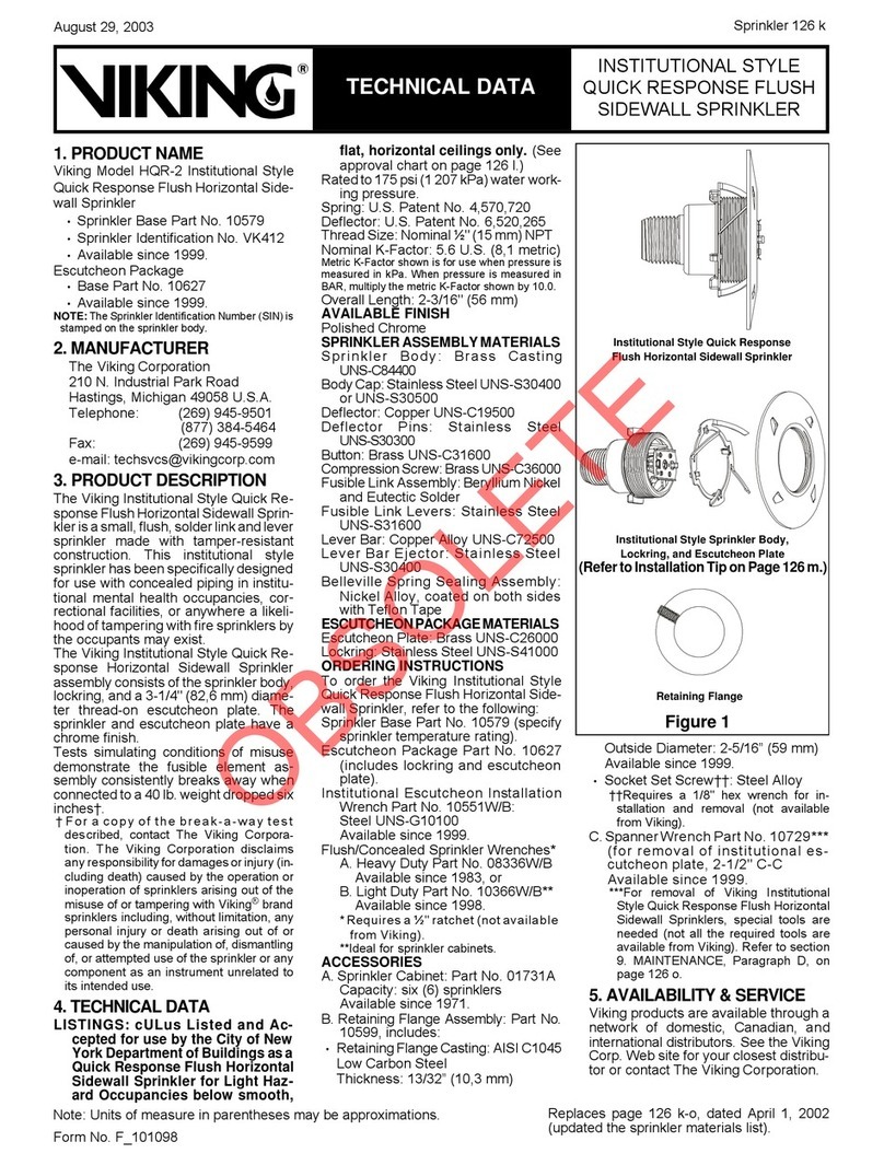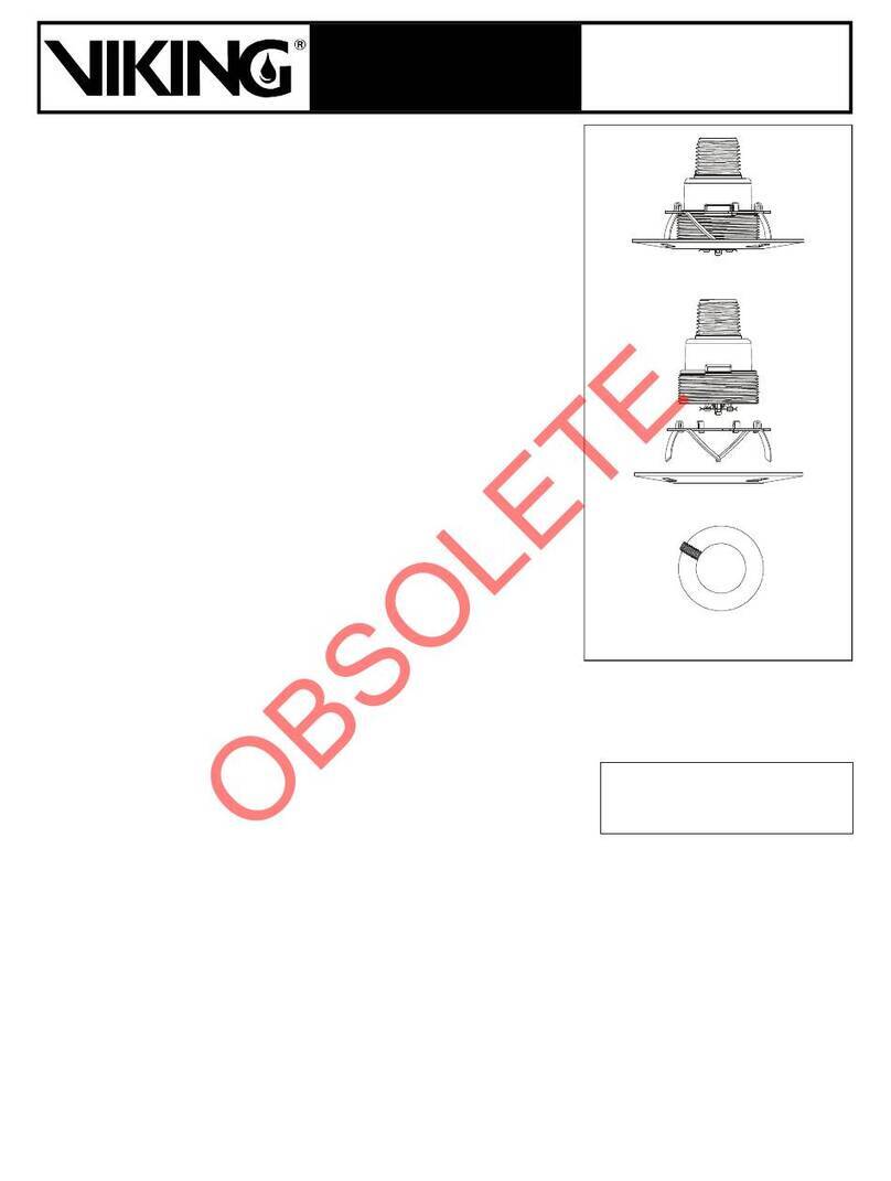
ESCUTCHEON MATERIALS
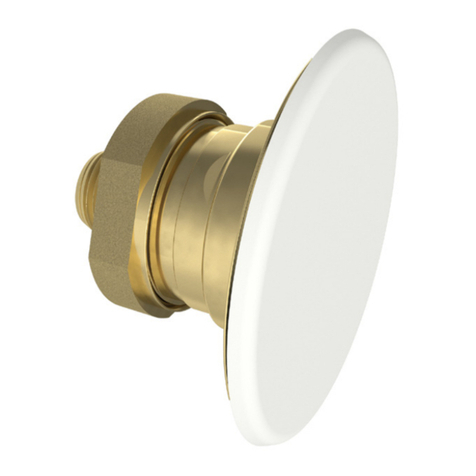
1. Adjustable Standard Dry Escutcheon:
Brass UNS-C26000 or UNS-C26800
2. Recessed Dry Escutcheon: Cold
Rolled Steel UNS-G10080
ACCESSORIES
Standard Dry Sprinkler Wrench: Part
No. 07297W/B
Recessed Dry Sprinkler Wrench: Part
No. 07565W/B***
***Requires a separate ½" ratchet (not available
from Viking).
Replacement Escutcheons:
1. Adjustable Standard Dry Escutcheon:
Base Part No. 08086F
2. Recessed Dry Escutcheon: Base Part
No. 05459A
AVAILABLE FINISHES
•Recessed: Chrome-Enloy®(patents
pending) or White Polyester
•Standard Adjustable: Chrome-Enloy®
•Plain Barrel: Chrome-Enloy®or Brass
(sprinkler only)
5. ORDERING INFORMATION
For proper shipment, specify model, fin-
ish, temperature rating, escutcheon
type, and length (“A” Dimension. Dry
horizontal sidewall sprinklers are or-
dered in specific lengths noted as the “A”
dimension (see Figures 1 through 4).
The “A” dimension is the distance from
the face of the fitting (tee) to the finished
surface of the wall in which it is to be in-
stalled. The dry horizontal sidewall
sprinkler must be ordered and manufac-
tured specifically for one of three styles
of installation: with the adjustable re-
cessed escutcheon (see Figure 1), with
the adjustable standard escutcheon (see
Figures 2 and 3), or with the plain barrel
(see Figure 4). For limits of adjustment for
the recessed escutcheon, see Figure 1.
Details and limits of adjustment for the
standard escutcheon style, with 2" (50,8
mm) of adjustment, are shown in Figure 2.
6. INSTALLATION
WARNING: Viking sprinklers are manu-
factured and tested to meet the rigid re-
quirements of approving agencies. The
sprinklers are designed to be installed in
accordance with recognized installation
standards. Deviation from the standards
or any alteration to the sprinkler after it
leaves the factory including, but not lim-
ited to: painting, plating, coating, or modifi-
cation, may render the sprinkler inopera-
tive and will automatically nullify the ap-
proval and any guarantee made by Viking.
A. Viking sprinklers are to be in-
stalled in accordance with the lat-
est edition of Viking technical
data, the latest standards of NFPA,
FM Global, Loss Prevention Coun-
cil, Assemblee Pleniere, VdS or
other similar organizations, and
also with the provisions of gov-
ernmental codes, ordinances, and
standards, whenever applicable.
The use of dry horizontal sidewall
sprinklers may be limited due to
occupancy and hazard. Refer to
the AHJ prior to installation.
B. Sprinklers must be handled with care.
They must be stored in a cool, dry place
in their original container. Never install
sprinklers that have been dropped,
damaged in any way, or exposed to
temperatures in excess of the maxi-
mum ambient temperature allowed (re-
fer to Table 1). Such sprinklers
should be destroyed. Never install
any glass-bulb sprinkler if the bulb is
cracked or if there is a loss of liquid from
the bulb. If a glass bulb lacks the ap-
propriate amount of fluid, it should be
set aside and returned to Viking (or
an authorized Viking distributor) for
analysis as soon as possible. If the
sprinkler is not returned to Viking, it
should be immediately destroyed.
C. Viking Standard Response Dry Hori-
zontal Sidewall Sprinklers are not in-
tended for use in corrosive environ-
ments. Use only sprinklers listed for
corrosive environments when sub-
ject to corrosive atmospheres.
WARNING: Viking dry sprinklers are
to be installed in the 1" outlet or run of
malleable or ductile iron threaded tee
fittings that meet the dimensional re-
quirements of ANSI B16.3 (Class
150), or cast iron threaded tee fittings
that meet the dimensional require-
ments of ANSI B16.4 (Class 125),
even at branch line ends. The
threaded end of the dry sprinkler is de-
signed to allow the seal to penetrate
and extend into the fitting to a prede-
termined depth. This prevents con-
densation from accumulating and
freezing over the sprinkler seal.
1. DO NOT install the dry sidewall
sprinkler into a threaded elbow,
coupling, or any other fitting that
could interfere with thread penetra-
tion. Such installation will dam-
age the brass seal.
2. DO NOT install the dry sidewall sprin-
kler into a coupling or fitting that will
allow condensation to accumulate
above the seal, when located in an
area subject to freezing.
3. NEVER try to modify the dry horizon-
tal sidewall sprinkler. The sprinklers
are manufactured for specific “A” di-
mensions and cannot be modified.
D. The sprinkler must be installed after
the piping is in place to prevent me-
chanical damage. Keep sprinklers with
protective caps or bulb shields con-
tained within the caps or shields during
installation and testing, and any time
the sprinkler is shipped or handled.
1. Before installing the sprinkler, make
certain the “A” dimension is correct
and the sprinkler is the appropriate
model and style, orifice size, and
temperature rating.
Sprinkler 102 b
TECHNICAL DATA
½" (12,7 mm)
3-1/16"
(77,8 mm)
4" (102 mm) Minimum
6" (152 mm) Maximum
For "A" Dimension:
1. Determine the distance from face of tee to face
of finished wall.
2. Round to nearest 1/4" (6,35 mm) between 3-1/4"
and 47-1/2” (82,5 mm and 1 207 mm).
NOTE: The sprinkler will be recessed approximately
5/16" (7,9 mm) with 5/8" (15,8 mm) horizontal
adjustment
available.
Minimum ceiling hole size:
2-1/8" (54 mm) diameter.
Maximum ceiling hole size:
2-1/2" (63,5 mm) diameter.
Ceiling
Wall
Figure 1: Adjustable Recessed Dry Horizontal Sidewall Sprinkler
5/16" (7,9 mm) Outward Adjustment
1-7/8" (47,6 mm) Minimum
2-1/2" (63,5 mm) Maximum
Available
Adjustment
5/16" (7,9 mm) Inward Adjustment
STANDARD RESPONSE
DRY HORIZONTAL
SIDEWALL SPRINKLERS
December 17, 2004

