Viking PB-100 Installation and operating instructions

PB-100
PB-100
Polling/Diagnostics Kit
for the 1600A Series
November 29, 2001
Provide Diagnostics and Polling to your ADA
Compliant Emergency Phone Customers
P
Ph
ho
on
ne
e.
..
..
.7
71
15
5.
.3
38
86
6.
.8
88
86
61
1
i
in
nf
fo
o@
@v
vi
ik
ki
in
ng
ge
el
le
ec
ct
tr
ro
on
ni
ic
cs
s.
.c
co
om
m
h
ht
tt
tp
p:
:/
//
/w
ww
ww
w.
.v
vi
ik
ki
in
ng
ge
el
le
ec
ct
tr
ro
on
ni
ic
cs
s.
.c
co
om
m
• Compatible with Windows 95, 98, ME, NT 4.0,
and 2000
• Non-volatile E2memory (no batteries required)
• Programmable polling date/time intervals
• Complete contact record storage up to 500
records
• Stores "Success" and "Failure" logs in ASCII
text mole files
• 9-pin RS-232 cable included
• RS-232 ASCII command capabilities
• 20 digit Touch Tone buffer
• Dials Touch Tones 0-9, ,, #and two second
pauses
• Automatic line seizure
• One year limited warranty
• Polling emergency phones in...
Elevators
"Area of Refuge" sites
Parking ramps
Automated Tellers (ATM)
Entryways
Campus security sites
Roadside emergency sites
Stairwells in public buildings
• Polling any device that can return DTMF Touch
Tones
• Polling security guards on rounds
Power: 120V AC/12V DC 500mA, UL listed adapter provided
Dimensions: 127mm x 127mm x 25mm (5" x 5" x 1.5")
Weight: 1.36 kg (3 lbs.)
Environmental: 0°C to 32°C (32°F to 90°F) with 5% to 95% non-
condensing humidity
P.C. Interface: 9-pin RS-232 (cable included)
Software/Hardware Requirements:
• IBM Compatible personal computer with an available serial port
CD-rom drive, and Windows compatible sound card
• Windows: 95 or 98 (with OLE32 updates), NT 4.0 (service
pack 6 or higher ), 2000 (service pack 2 or higher)
• 5MB of hard drive space
• 8MB of free physical RAM
T
TE
EL
LE
EC
CO
OM
MS
SO
OL
LU
UT
TI
IO
ON
NS
SF
FO
OR
RT
TH
HE
E2
21
1S
ST
TC
CE
EN
NT
TU
UR
RY
Y
A
Ap
pp
pl
li
ic
ca
at
ti
io
on
ns
s
F
Fe
ea
at
tu
ur
re
es
s
S
Sp
pe
ec
ci
if
fi
ic
ca
at
ti
io
on
ns
s
Devices that are polled successfully are stored in a "success" log while devices that returned any
kind of error are stored in a "failure" log for follow up at a later time.
The PB-100 provides centralized polling and diagnos-
tics of all Viking 1600 and 1600A series emergency
phones through a standard Windows 9x/NT P.C. In
addition, any device or person capable of returning
DTMF Touch Tones can be automatically polled.
Up to 500 individual phones can be polled, at
timed intervals, for the diagnosis of basic opera-
tion. The included software provides storage of
complete contact/location records associated
with the phones ID.
APPLICATION
APPLICATION
N
No
ot
te
e

L
Li
ic
ce
en
ns
se
eA
Ag
gr
re
ee
em
me
en
nt
t/
/W
Wa
ar
rr
ra
an
nt
ty
y
THE SOFTWARE, FIRMWARE, SOURCE CODE, HTML CODE, DOCUMENTATION OR ANY
OTHER ACCOMPANYING COMPUTER FILES (hereafter referred to as "THE FILES") ARE PRO-
VIDED "AS IS" AT "NO CHARGE" AND WITHOUT WARRANTY OF ANY KIND, INCLUDING, BUT
NOT LIMITED TO, THE IMPLIED WARRANTIES OF MERCHANTABILITY OR NON-INFRINGE-
MENT. Because of the various hardware and software environments into which the FILES may be
put, NO WARRANTY OF FITNESS FOR A PARTICULAR PURPOSE IS OFFERED. Viking explic-
itly disclaims the fitness or usefulness of all files and/or software, or the information contained here-
in, for any purpose.
Good data processing procedure dictates that any program be thoroughly tested with non-critical
data before relying on it. The user must assume the entire risk for using “THE FILES”.
TO THE FULLEST EXTENT PERMISSIBLE PURSUANT TO APPLICABLE LAW, IN NO EVENT
SHALL VIKING ELECTRONICS, INC. NOR ANY OTHER PARTY INVOLVED IN CREATING,
PRODUCING, DELIVERING, INSTALLING OR USING "THE FILES", BE HELD LIABLE FOR ANY
SPECIAL, DIRECT, INCIDENTAL, CONSEQUENTIAL, INDIRECT OR PUNITIVE DAMAGES
ARISING OUT OF YOUR ACCESS TO, USE OF, OR INABILITY TO USE "THE FILES" (INCLUD-
ING, WITHOUT LIMITATION, DAMAGES FOR LOSS OF BUSINESS PROFITS, BUSINESS
INTERRUPTION, LOSS OF BUSINESS INFORMATION, OR ANY OTHER PECUNIARY LOSS)
ARISING OUT OF THE USE OF OR INABILITY TO USE "THE FILES", EVEN IF VIKING ELEC-
TRONICS, INC. HAS BEEN ADVISED OF THE POSSIBILITY OF SUCH DAMAGES.
BECAUSE SOME STATES AND JURISDICTIONS DO NOT ALLOW THE EXCLUSION OR LIMI-
TATION OF LIABILITY FOR CONSEQUENTIAL OR INCIDENTAL DAMAGES, THE ABOVE LIM-
ITATION MAY NOT APPLY TO YOU.
Because “THE FILES” are provided "AS IS" at "NO CHARGE," it is done so with the condition that
LIMITED, and in most cases, NO TECHNICAL SUPPORT WILL BE PROVIDED for the use or
installation thereof.
All OF "THE FILES" ARE AND WILL DURABLY REMAIN THE SOLE COPYRIGHTED COMMER-
CIAL PROPERTY OF VIKING ELECTRONICS, INC. "THE FILES” are NOT PUBLIC DOMAIN,
FREEWARE OR SHAREWARE. You may NOT REDISTRIBUTE OR REPRODUCE THESE FILES
AND/OR SOFTWARE in any form, electronic or otherwise WITHOUT THE EXPRESS WRITTEN
PERMISSION OF VIKING ELECTRONICS, INC.
If you DO NOT ACCEPT OR AGREE TO ALL of the above terms, conditions, and disclaimers, you
must DELETE all of "THE FILES" from your local or network drive immediately and return or
destroy the media on which "THE FILES" were delivered. Any and all USE or INSTALLATION of
"THE FILES" will be considered ACCEPTANCE of all TERMS, CONDITIONS and DISCLAIMERS.
If any provision of this Agreement shall be unlawful, void, invalid or for any reason unenforceable
then that provision shall be deemed severable from this Agreement and shall not affect the validi-
ty and enforceability of any remaining provisions.

S
So
of
ft
tw
wa
ar
re
ea
an
nd
dI
In
ns
st
ta
al
ll
la
at
ti
io
on
n
This software package was developed for use in conjunction with the Viking Electronics PB-100 polling box. The PB-
100 is a multipurpose device capable of performing a large variety of equipment and personnel polling duties. The PB-
100 polling software directly supports the polling of any telecom device capable of returning DTMF Touch Tones, specif-
ically the 1600A Series Emergency Phones.
Each PB-100 data file has the capacity to store information for up to 500 unique devices, any or all of which may be
scheduled for polling on a timed basis. Since you may have multiple data files, the total number of polled devices is
essentially unlimited.
Important: Limitations are introduced by the logistics of dialing a number of devices at a particular time. For exam-
ple: if 15 different devices are scheduled for polling at 3:00pm, devices 2-15 device will naturally receive polling some
time later than 3:00pm. If each polling event takes an average of 1 minute, device 15 will be polled sometime around
3:15pm. If new polling events are scheduled for 3:15pm, the new events will be integrated and polled with the 3:00pm
group, already in progress. It is important to keep these practical limits in mind when setting up your polling sched-
ule(s).
Note: The Polling Software will ONLY install and/or run on the Windows 95, 98, ME, NT 4.0, or 2000 platforms with
the PB-100 hardware attached.
A. About the Software
USE ONLY LISTED
CLASS 2 POWER
SOURCE 12VDC
O.5A MAX
LINEPHONE
SERIAL DATA
(RS-232) AUDIO
IN AUDIO
OUT
Serial
Port
The PB-100 comes complete with a telco cord, serial cable, audio cables and a 12V DC power adapter.
H
Ha
ar
rd
dw
wa
ar
re
eI
In
ns
st
ta
al
ll
la
at
ti
io
on
n
120V AC
Phone Line
RS-232 Serial Cable
12V DC Adapter
(included)
Telecom Device
Step 1. Using the telco cord, connect a phone line to the rear panel jack labeled “LINE”. If the PB-100 is to be used in series with
another piece of equipment, the telecom device can be plugged into the “PHONE” jack.
Step 2. Connect one end of the 9 pin serial cable into the jack labeled “SERIAL DATA” and the other end into an open serial port
of the P.C.
Step 3. If audio is to be used through the PB-100, connect the “Audio Out” port of the sound card to the “AUDIO IN” port of the
PB-100, and “Audio In” or “Mic In” of the sound card to the “AUDIO OUT” port of the PB-100.
Step 4. Plug the 12V DC power adapter (included) into the rear panel power jack.
Rear View of the
PB-100
Rear View of the P.C.
B. System Requirements
1. Hardware Requirements
• IBM Compatible personal computer with: Windows 95, 98 or ME (with OLE32 updates), Windows NT 4.0 (service
pack 6 or higher), Windows 2000 (service pack 2 or higher).
• PB-100 hardware.
• Available RS-232 serial port.
• Male sub-D 9 pin cable (provided with PB-100 hardware).
• Windows compatible sound card.
• 5MB minimum free hard drive space for each installation.
• 8MB of free physical RAM for each Viking application running.

S
So
of
ft
tw
wa
ar
re
eP
Pr
ro
og
gr
ra
am
mm
mi
in
ng
g
Select the “New” option under the “File” menu, and the user will
be prompted to select a filename and location for the new data
file. New PB-100 data files are given the extension .pb1 by
default. While the user may use any legal filename and/or exten-
sion for a PB-100 data file, we recommend using the .pb1 exten-
sion to minimize confusion or possible conflicts with registered
file types.
B. Creating a New Data File (see Diagram A)
• Internet Explorer or Netscape Navigator Version 4 or newer to navigate CD contents.
• Windows: 95 or 98 (with OLE32 updates), NT 4.0 (service pack 6 or higher ), 2000 (service pack 2 or higher).
• Adobe Acrobat Reader®version 4.x or newer to view Product and Software Documentation.
2. Software Requirements
C. Installing Software
D. Un-Installing Software
Step 1. Connect the hardware as shown in “Hardware Installation”.
Step 2. Insert the Viking master CD to start the program.
Step 3. Follow the instructions on the CD.
Step 1. Go to “Control Panel”, then select “Add/Remove Programs”.
Step 2. Select the Viking software you want to remove.
Step 3. Click “Remove”.
Note: If you have disabled the “Auto-Run” feature on your computer and the CD does not automatically start, double
click the setup.htm file in the root directory of your CD-Rom drive.
MODEL PB-100
VIKING ELECTRONICS, HUDSONWI 54016
1 2 3 4
1 2 3 4
POLLING BRIDGE
ON
OFF
RESET
STATUS
VIKING©
P
Pr
ro
og
gr
ra
am
mm
mi
in
ng
g
Switch
1
1
2
3
4
ON/OFF
OFF
ON
-
-
-
Description
1600A Series polling mode enabled
1600A Series polling mode disabled
(for future use)
(for future use)
(for future use)
If a device record already exists, it can be loaded by selecting
the “File” menu and selecting “Open”. The user may then browse
directories and files on the system, and locate the PB-100 data
file (*.pb1) to load.
C. Opening a Device Record (see Diagram A)
Serial communication with the PB-100 is set to a fixed standard of 9600,n,8,1 and cannot be changed. Set your COM
port setting in the Control Panel to match these configurations. The “COM Port Select” designation (1-4) is set on the
“Utility” tab by selecting one of four radio buttons corresponding to the PC's COM ports. On most standard PCs, this
will be either COM1 or COM2. Refer to your P.C. hardware documentation if you are unable to determine which port
to use for communicating with the PB-100.
Provided on the “Utility” tab window is a diagnostic tool for testing and verifying communications between the PC and
the PB-100. To verify that communication with the PB-100 is
working, simply enter in the letter "A" in the “COM Port Send”
window and then click the “Send” button. The “COM Port
Receive” window should display a "K" if the PB-100 is on-line. If
this test fails, check your COM Port selection and serial cabling.
Finally, verify that the PB-100 has power.
A. Serial Port Configuration (see Diagram A)
Diagram A
Important: New records entered and changes made to existing records are temporary until the "Apply" button is pressed and the
file is saved to a drive. To avoid losing data, please "Save" your work often and always save before the program is terminated.

The PB-100 Software allows a maximum of up to 500 indi-
vidual device records to be entered into a single data file.
To enter an individual device record select the “Information”
tab and click on the “New” command button (each addition-
al device record is added by selecting “New”).
Device ID Code (required) - Fill in the “Device ID Code” -
all device records must have a ID number to be recognized
by the software. This ID number corresponds to the touch-
tone string the called device must send in order to receive a
successful response. The “Device ID Code” may contain
digits "0-9", "#", or ",". While “Device ID Codes” need not
be unique, we recommend using unique codes as standard
practice.
Phone Number (required) - Next fill in the “Phone Number”
that will be dialed for this device. For any polling to take
place a Phone Number must be entered. The digits for the
phone number can be "(", ")", "0-9", "#", ",", "-" or "," for a
2 second pause.
All other fields on the Information tab are for reference only
and are not required, though they should be filled out to cre-
ate a complete device record. These include “Company,”
“Street,” City, State Zip,” and “Device Notes.”
D. Entering Information for a Device (see Diagram B)
Diagram B
The “Success Log” and “Failure Log” files contain the
accumulated response data for all completed polling
events. When a polled device responds with the correct
“Device ID Code,” the information is logged into the
“Success log,” and then displayed in the corresponding
window with the message "Received ID". In the event
that a polled device fails to respond, or returns an incor-
rect response, the information is logged to the “Failure
Log,” and then displayed in its corresponding window
along with one of the following error messages: "No
Response", "User Cancelled", "No Phone Number", "PB-
100 error" or "Invalid ID". The location and names of
these two files are set on the “Utility” tab and the files are
saved as an ASCII text file. The default file names are
success.log and failure.log respectively. If required, the
user may change the name or location of either log file by
using the “Browse” command button(s) to specify a loca-
tion.
E. The Success and Failure Logs Diagram C
Diagram D

An individual device record can be modified at any time by selecting a particular field in the “Information” or “Schedule”
tabs and altering the data. The changes are only temporary until the “Apply” command button is clicked on the
“Information” or “Schedule” tab. Furthermore, unless the device record is then saved, the information will be lost once
the program has been terminated.
H. Modifying a Device Record (see Diagram E and F)
An individual device record can be deleted by clicking on the
“Delete” button on the “Information” tab.
I. Deleting a Device Record (see Diagram F)
(see Diagram F) If a field for a device record is modified
by mistake, simply click on the “Cancel” command button
on the “Information” or “Schedule” tab. Note: The Cancel
button cannot undo changes once a record has been
saved.
J. Cancelling a Change to a Device Record
After the information for a device has been entered, a schedule
for the polling process can be set up. To enter a schedule for a
device click on the “Schedule” tab.
Response Timer - This timer controls how long the PB-100 will
wait (after dialing is completed) for the “Device ID Code” to be
returned. Clicking on the up/down arrows will change the
response time in 5 second increments, from 15 to 90 seconds.
Retry Count - This counter sets the number of times the PB-100
will re-dial a device if there is no initial response (the Response
Timer has elapsed). Clicking on the up/down arrows will change
the retry count from 1 to 9 counts.
Poll Device - A device can be scheduled to be polled weekly on
specified days of the week, or monthly on a particular date. The
polling for a particular device may also be disabled. If “Weekly”
is selected, check off any or all boxes for the day of the week the
device should be polled. If “Monthly” is selected, enter the date
for the polling to take place by clicking on the up/down arrows for
this selection.
Poll Time - The time of day that polling should take place for a
device is entered here. To change the polling time click on the up/down arrows to set the polling time, adjustable in 15-
minute increments.
F. Setting the Schedule for a Device (see Diagram E) Diagram E
Using the up/down arrows in the middle of the “Information” or “Schedule” tabs, the user can click to select the next
device record, or the previous device record in the currently loaded data file.
The user can sort the current data file by one of four criteria using the pull down menu on the “Information” tab. The
records may be sorted by “Device ID Code”, “Phone Number,” “Company” or “Name.” If required, sort the device record
and re-save it to maintain the record in an order which suits your individual needs. After sorting by one of the four list-
ed criteria, a specific record can be found by entering a search string in the “Find” window on the “Information” tab.
G. Accessing Other Device Records in a Data File (see Diagram E and F)
New records entered and changes made to existing records
are temporary unit the "Apply" button is pressed and the file
is saved to a drive. To avoid losing data, please "Save" your
work often and always save before the program is terminat-
ed. To save a device record(s) simply select the “File” menu
item and select “Save” if the file exists already, or “Save As”
if a new record is being created. PB-100 data files are
saved with a .pb1 extension by default.
K. Saving a Device Record (see Diagram F)
Diagram F

By selecting the “Print” menu item the “Current Record,”
“Success Log,” or “Failure Log” may be output to a printer.
Printing the “Current Record” prints only the single record
listed on the Information tab, while printing the “Success” or
“Failure” Logs prints only the response records currently
shown in the “Display” tab.
Note: The Print menu option does not allow you to print the
contents of the success.log or failure.log to the printer. To
print out the entire log files simply use a text editor program
such as Notepad or Microsoft Word to open the success.log
or failure.log file and print them from within the text editor
program.
D. Printing Records (see Diagram H)
O
Op
pe
er
ra
at
ti
io
on
n
The “Display” window shows the current polling activity in LIFO (Last In, First Out) fashion. Thus, the device record
response at the top of the display is always the most recent response received. If the polling activity is stopped, the
display logs can be scrolled through using their scroll bars and buttons. In addition, if more information is required on
a specific device record, double click the “Device ID Code” (ID:) or a telephone number (Ph:) in the record in either dis-
play window. This action brings up the “Information” tab, which will then display the full record for that device.
A. Start, Stop and Clear Buttons (see Diagram G)
Clicking the “Start” command button at the bottom of any PB-
100 tab starts the polling process with the current data record.
The software initially checks to see if a PB-100 is connected. If
a PB-100 is found, the polling software checks (starting from
the first record) if the PC clock is greater than the assigned
polling time. If so, the Polling software automatically dials the
phone number associated with the device to be polled and then
waits for a response. If a valid “Device ID Code” is received the
information is logged to the “Success Log” with the message
"ID Received". If the polled device fails to respond within the
time allotted by the “Response Timer” setting, then the polling
software will either log "No Response" to the “Failure Log”, or
try to poll again if the “Retry Counter” is set to greater than one.
If the polled device responds with an “Invalid ID”, the “Error
Log” will receive "Invalid ID:" followed by the actual ID received.
Other possible Failure log errors are "User Cancelled", "No
Phone Number", or "PB-100 error".
The user may interrupt the polling process at any time by click-
ing the “Stop” button. When polling is manually stopped, the
information for the device currently being polled will be logged
to the “Failure Log” with the message "User Cancelled".
If polling is not currently in progress, the user may clear the “Success Log” or “Failure Log” displays by clicking the
appropriate “Clear” button on the “Display” tab. It is worth noting that this action does not clear the success.log and
failure.log files. To clear these files, browse to their locations and manually delete them. New success.log and fail-
ure.log files will be created the next time the PB-100 software is used.
B. The Display Window (see Diagram G)
The user can select a particular device record by any of the
previously described methods, and then switch to the
Schedule tab to poll the device manually. Clicking on the
“Poll Device Now” button will immediately perform polling for
the selected device. Clicking “Poll Device Now” polls only the
device record listed and then halts. The “Poll Device Now”
feature is a valuable tool to verify that a new or modified
device record contains the correct telephone number and
“Device ID Code.”
C. Poll Now (see Diagram H)
Diagram G
Diagram H

Due to the dynamic nature of the product design, the information contained in this document is subject to change without notice. Viking Electronics, and its affiliates and/or
subsidiaries assume no responsibility for errors and omissions contained in this information. Revisions of this document or new editions of it may be issued to incorporate
such changes.
Fax Back Doc 860
ZF301330 Rev A
Printed in the U.S.A.
P
Pr
ro
od
du
uc
ct
tS
Su
up
pp
po
or
rt
tL
Li
in
ne
e.
..
..
.7
71
15
5.
.3
38
86
6.
.8
86
66
66
6F
Fa
ax
xB
Ba
ac
ck
kL
Li
in
ne
e.
..
..
.7
71
15
5.
.3
38
86
6.
.4
43
34
45
5
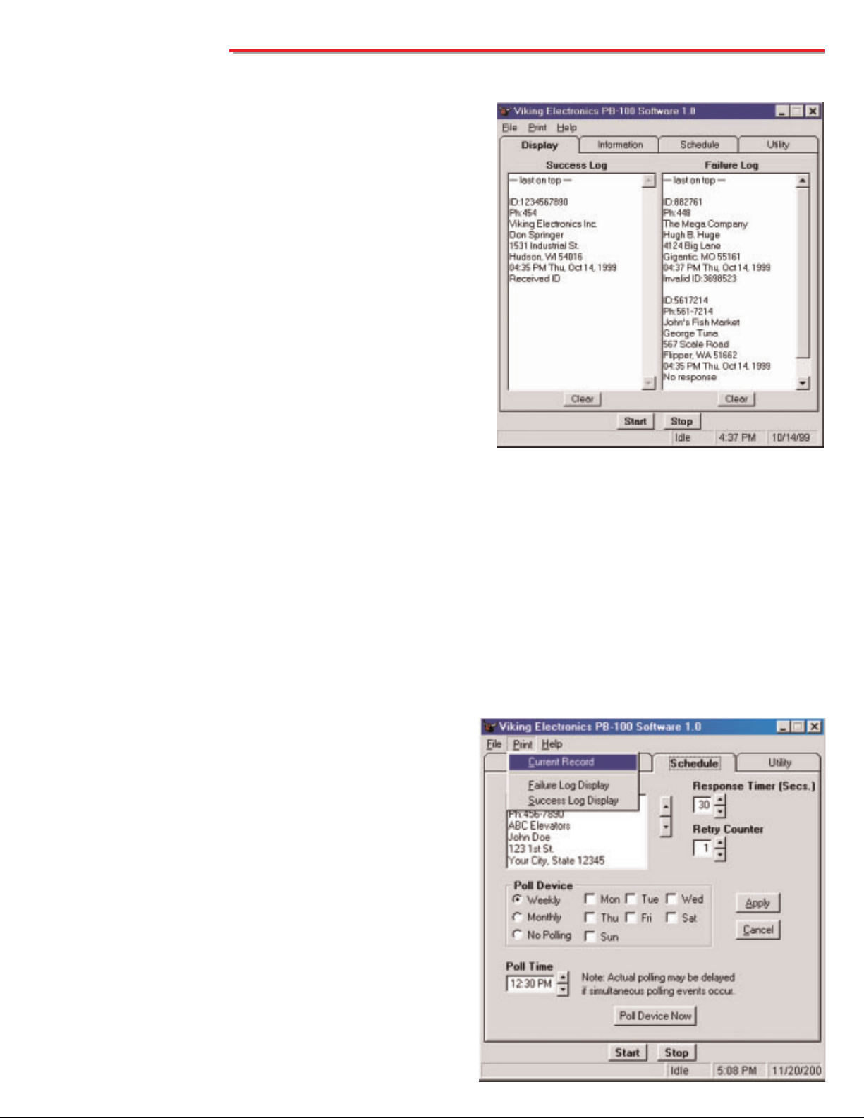
There are three selections under the Help menu. 'Help File' loads the Adobe Acrobat version of this document, while
'About' brings up a box providing information about the software development, and the current revision level of the soft-
ware. The 'Viking Tech Support' selection activates an HTML hyperlink to the Viking Electronics Technical Support
website at http://www.vikingelectronics.com/techsupport/support.html. Limited support will be provided.
E. Getting Help
A
AD
DA
AC
Co
om
mp
pl
li
ia
an
nt
tP
Ph
ho
on
ne
es
s
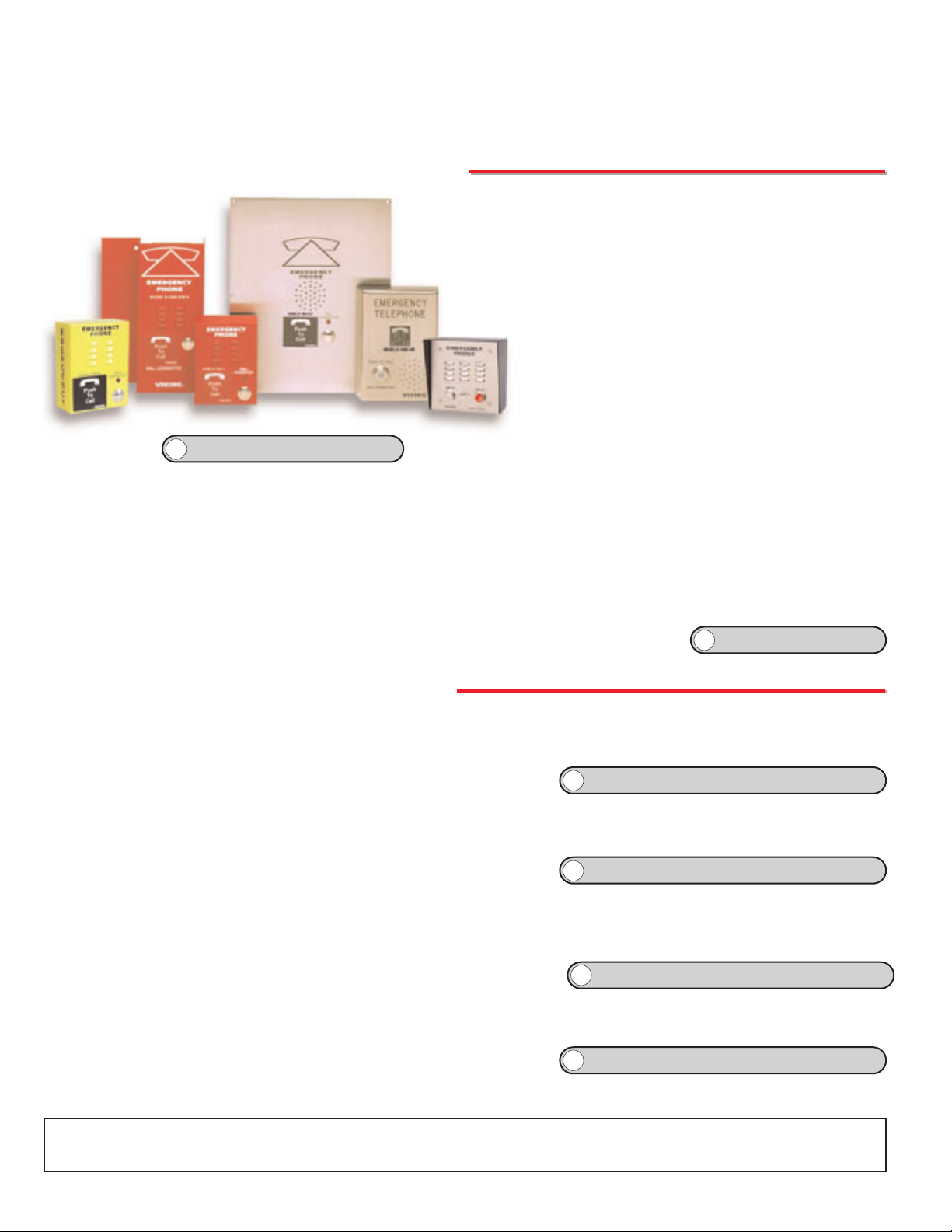
to identify the location of the emergency call and then initiate the call connected LED light. Alternatively, a
DTMF Touch Tone code may also be delivered. All programming parameters, including phone numbers and
location numbers, are stored in non-volatile E2memory. All units are phone line powered, requiring no batteries
or external power and are compatible with common Central Station Monitoring equipment.
For outdoor or harsh environments, select 1600A Series phones are available with Enhanced Weather
Protection (EWP). EWP products feature rubber gaskets and boots, hand soldered silicon sealed connections,
gel filled tip and ring connectors, as well as urethane potted circuit boards with weather sealed, field-adjustable
trim pots and DIP switches for easy on-site programming.
The 1600A Series ADA Compliant Emergency Phones are
designed to provide quick and reliable handsfree communica-
tion over the public switched telephone network. All 1600A
Series phones meet ADA requirements for
elevator/emergency telephones, and can be pro-
grammed from any Touch Tone phone. The phones can
dial up to 5 programmable emergency num-
bers, as well as 2 central station numbers. In
addition, the E-1600-20A features an "Info" but-
ton that will dial up to 3 non-emergency num-
bers.
The 1600A Series phones can be programmed
to automatically deliver a digital announcement
E-1600-45A
K-1600-EHFA
E-1600A
E-1600-02A E-1600-03A
E-1600-20A
?
?Need More Information on EWP?
Call (715) 386-4345 and select 859.
?
?Need More Information on the 1600A Series?
Call (715) 386-4345 and select 215.
O
Ot
th
he
er
rP
PB
B-
-1
10
00
0S
So
of
ft
tw
wa
ar
re
e
The AES-2000 Accessible Entry System can be programmed remotely using the PB-100 and the AES-2000 Programming Software.
Both data and audio can be uploaded to the AES-2000 including names, phone
numbers, audio queues and other required programming variables.
AES-2000 Programming Software
The All Call Dialing program maintains a list of names and phone numbers in a Microsoft Access database. When started, the software
calls each number stored in the database and plays a selected wave (.wav) file
stored on your computer's hard drive.
All Call Dialer/Announcer
Smart Terminal is diagnostic program that allows the user to send and receive data directly to COM1 or COM2 of your PC. ASCII, Hex
and Decimal data can be entered, decoded and sent out the selected ports. This utility is useful for troubleshooting the connection
between the PB-100 and your PC. Do this to assure you have the correct com
port configured for the PB-100.
Smart Terminal Diagnostic Software
The Information Provider turns the PB-100 and your PC into a multiple message ring trip announcer. The software allows you to organ-
ize messages into multiple menu levels (up to 10). The Information Provider software provides an easy to follow spread sheet like dis-
play for organizing the messages and transfer functions.
Multi-Message Information Provider Software
?
?Need More Information on the AES-2000 Programming Software?
Call (715) 386-4345 and select 202.
?
?Need More Information on the All Call Dialer/Announcer?
Call (715) 386-4345 and select 861.
?
?Need More Information on the Message Info Provider Software?
Call (715) 386-4345 and select 862.
?
?Need More Information on the Smart Terminal Software?
Call (715) 386-4345 and select 863.
Other manuals for PB-100
2
Table of contents
Other Viking Test Equipment manuals