ETI IR-500 User manual

User Manual
Product Code


3
Use this instrument only as specified in this manual, otherwise, the protection
provided by the instrument may be impaired.
Please note the warnings and cautions listed below.
WARNINGS
touch the IR target surface of the unit.
The temperature of the IR target surface is the same as the actual temperature
shown on the display. If the unit is set at 500 °C and the display reads 500 °C,
the target surface is 500 °C. The top of the instrument case may exhibit extreme
temperatures for areas close to the IR target surface.
turn off the unit at temperatures higher than 50 °C. This could create
a hazardous situation.
connect and operate this unit without a properly grounded, properly
polarized power cord.
is used in the operation of this equipment. Severe injury or death
may result if personnel fail to observe safety precautions. Before working inside the
equipment, turn the power off and disconnect the power cord. Overhead clearance
is required.
place this instrument under a cabinet or other structure.
use this unit in conditions other than those listed in the environmental
conditions section (page 5).
operate near flammable materials.
Use of this instrument at for extended periods of time
requires caution. Completely unattended high temperature operation is not
recommended for safety reasons.
CAUTIONS
To avoid possible damage to the instrument, follow these guidelines.
plug the unit into 220V if the heater switches and fuse holder read
11OV. This action will cause the fuses to blow and may damage the instrument.
use fluids to clean the target surface.
change the values of the calibration constants from the factory set values.
The correct setting of these parameters is important to the safety and proper
operation of the calibrator.

4
The IR-500 Calibrator is mainly structured by 58 mm diameter target assembly
and dry-well temperature system controlled by a microcomputer. The external
reference thermometer is a metal cone with good heat-conducting ability, on the
surface of thermometer there is a oxide lm with emissivity 0.95.
The IR-500 Calibrator contains a class-A PT100 sensor with a temperature control
system and wind-cold device. The calibrator has rapid heating and cooling
functions and is switchable between °C/°F, which can be used for different
temperature unit calibrations.
The calibrator operates over a range of 50 °C to 500 °C with a temperature display
resolution of 0.1 °C.
3.GENERAL SPECIFICATIONS
Range 50 °C to 500 °C (122 °F to 932 °F)
0.1 °C
±1 °C below 100 °C
±2 °C from 100 °C to 200 °C
±3 °C from 200 to 500 °C)
±0.1°C at Temp<100 °C (±0.2 °F at Temp<212 °F)
±0.2 °C at 1OO °C<Temp<350 °C
(±0.4 °F at 212 °F<Temp<662 °F)
±0.4°C at 200°C<Temp<500 °C
(±O.8 °F at 392 °F<Temp<932 °F)
40 minutes to max
30 minutes to 100 °C (212 °F)
0.95 xed
Ø58 mm
110 volt AC, 3A or 230 volt AC (±10%), 1.5A
114 x 180 x 233 mm
Weight 2682 grams

5
Although the instrument has been designed for optimum durability and
trouble-free operation, it must be handled with care.
The instrument should not be operated in an excessively dusty or dirty
environment.
Maintenance and cleaning recommendations can be found in the
Maintenance section of this manual.
The instrument operates safely under the following conditions:
5-35 °C (41-95 °F)
15-80%
75kPa - 106kPa
Mains voltage within ±10% of nominal.
Vibrations in the calibration environment should be minimized.

6
Unpack the calibrator carefully and inspect it for any damage that may
have occurred during shipment. If there is shipping damage notify ETI Ltd
immediately.
Verify that the following components are present:
• Calibrator
• Power Cord
• User Manual
Place the calibrator on a at surface with at least 8 inches of free space around
the instrument. The stand may be swung down to raise the front of the
instrument from a horizontal position. Plug the power cord into a grounded
mains outlet (Note: this calibrator has two power specications of one model
NO:220V/AC and 11OV/AC, please make sure the power value is suitable for the
instrument before operation.)
Turn on the power to the calibrator by toggling the power switch on. The fan
should begin quietly blowing air through the instrument and the controller
display should illuminate after 3 seconds. After a brief self-test the controller
should begin normal operation. If the unit fails to operate please check the
power connection.
The heater will start operating to bring the temperature of the calibrator to
the set-point temperature and the display will begin to show the actual target
temperature.
The unit should be used with a secondary certied reference thermometer
(E.g. ETI Reference Thermometer product code 222-055)
Press "UP" or "DOWN" to change the set-point value.
Then press "SET". The calibrator will automatically control the target assembly
temperature to reach the set temperature in the stated time. The red LED
display will indicate the temperature of the target assembly. When the set-point
temperature is changed the controller switches the well heater on or off to raise
or lower the temperature. The displayed well temperature gradually changes
until it reaches the set-point temperature. The well may require 5 to 10 minutes
to reach the set-point depending on the span. Another 5 to 10 minutes is
required to stabilise within ±0.1 °C of the set-point. Ultimate stability may take 15
to 20 minutes more of stabilisation time.

7
The user should become familiar with the calibrator and its parts.
The back panel () consists of the power cord inlet, power switch, heater
voltage switch, and fan.
1Wind input
2Fuse of heater
3Fuse of temperature control system
4Power Input
5Power switch
Power Inlet - At the rear of the calibrator is the removable power cord inlet that
plugs into an IEC grounded socket.
Do not plug the unit into 220V if the unit is indicated as 110V. This
action will cause the fuses to blow and may damage the instrument.
Fan - The fan inside the calibrator has two speeds and runs continuously when
the unit is being operated to provide cooling for the instrument.
The fan runs slow for heating and maintaining operation and runs fast for rapid
cooling. Slots are provided for airow. The area around the calibrator must be
kept clear to allow adequate ventilation. The airow is directed out the front and
can be extremely hot

8
The front panel() consists of the controller display, controller keypad.
and target assembly.
Controller Display
1 The red LED (the rst line display) displays actual temperatures and
settings for selected scale °C or °F.
2 The green LED (the second line) displays the set-point value and shows
temperatures in units according to selected scale °C or °F.
3 The indicator of the operation state
• AT - Automotive parameter adjustment.(only used to factory for adjusted)
• OUT - The indicator of heat output with indication of the heating state of the
target assembly
• ALM1 - 0verload alarm when the target assembly temperature 4 °C higher than
the set temperature,indicates the heating power off
• ALM2 - 0verload alarm. when the target assembly temperature 4 °C higher
than the set temperature,indicates the cooling with strong wind
• °F - °F temperature indicator
• 0°C - 0°C temperature indicator.
The four button keypad allows easy setting of the set-point temperature.
• SET - Used to conrm parameter settings.
• - The enter button .Used with the set button to enter conguration mode.
• DOWN - Used to decrease temperature value and change the unit °C to °F.
• UP - Used to increase temperature value and change the unit °C to °F.
5 Target assembly, The target assembly is 58 mm in diameter and has an
emissivity at 0.95.
6 The test hole for the temperature sensor of the Reference thermometer.

9
Place the calibrator on a at surface with at least 8 inches of free space around
the instrument, with the instrument facing the user.
•Connect the calibrator to the power supply, ensuring correct voltage
(11OV or 220V).
•Press the "on" button to power the unit on.
The calibrator can display temperature in Celsius or Fahrenheit.
The temperature units are shipped from the factory set to Celsius and locked.
Press the "SET" and " " buttons at the same time.
After unlocking, rst press the "SET" button for three seconds, the red LED on the
rst line will display
the second line green LED will display "pt2";
Release the "SET" button and press the " " button, the green LED on the
second line will indicate the current temperature unit.
Press "DOWN" to select °F, press "UP" again to select °C. The chosen temperature
unit will ash.
Press "SET" to conrm. The green LED will stop ashing, press "SET" again for the
calibrator to return to operation mode.
In order to keep good operation, please lock the values after the temperature
unit changed.
To do this –
• Press the " " button three times, red LED on the rst line displays ,the
green LED on the second line displays "OFF".
• Press "UP" button two times, green LED will display
• Finally press "SET" to complete.
Turning off the power at high temperature will damage the sensor/heating parts
of the calibrator, therefore reduce the temperature to 50 °C after measurement.
When the temperature is reduced to 50 °C the user can then turn off the power.

10
This section shows you in detail how to operate the instrument temperature
controller using the front control panel. Using the front panel key-switches
and LED display the user may monitor the well temperature, the heater output
power and adjust the controller proportional band. The control buttons (SET,
DOWN, UP) are used to set the calibrator temperature set-point.
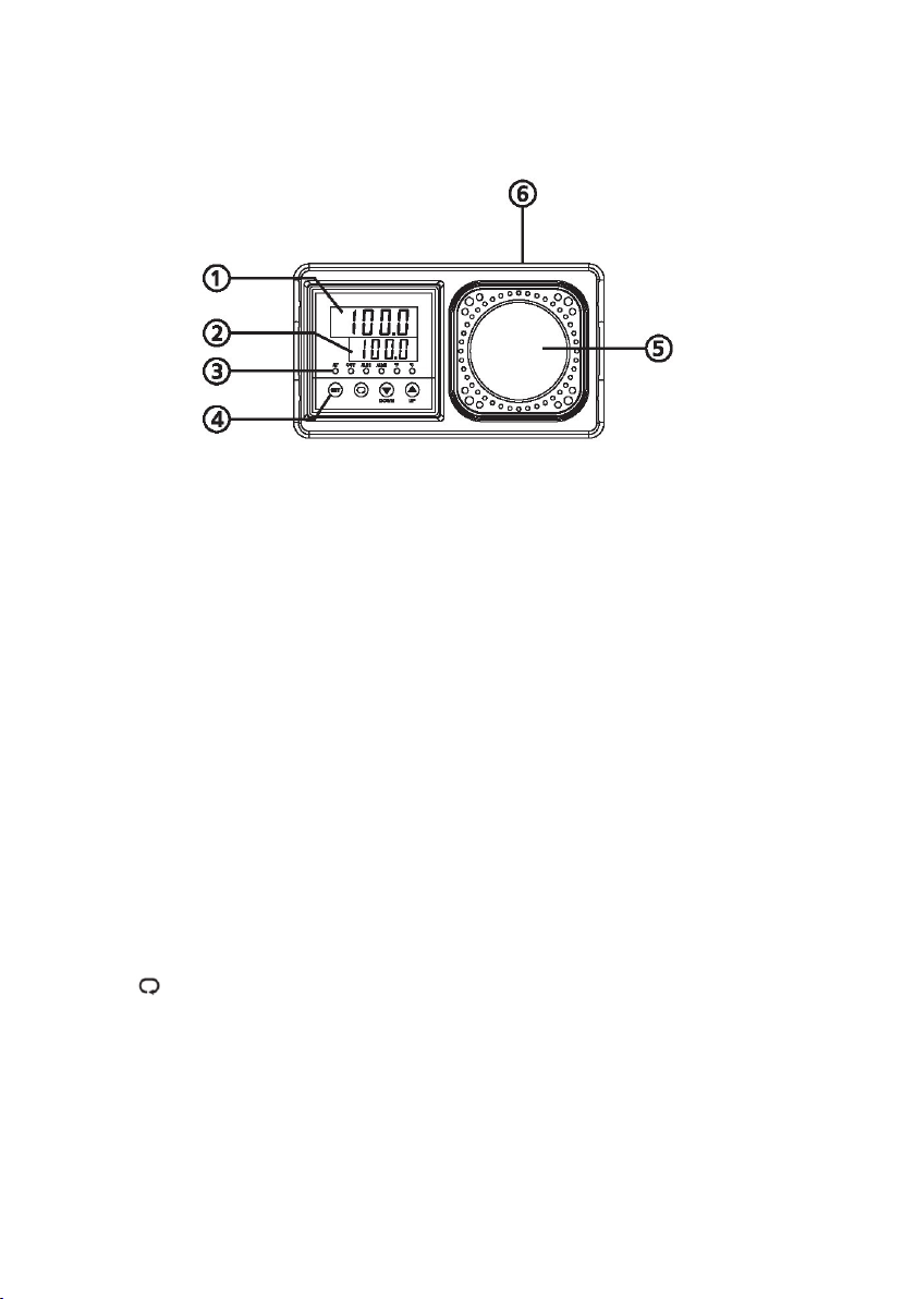
The digital LED display on the front panel allows direct viewing of the actual
well temperature. This temperature value is normally shown on the display.
The temperature is displayed in units, °C or °F, to the right.
The temperature set-point can be set to any value within the range and with the
resolution as given in the specications. Be careful not to exceed the safe upper
temperature limit of any probe inserted into the well.
• Press "UP" to increase temperature, or press "DOWN" to lower the temperature.
The temperature will be changed in 0.1° increments every time the button
is pressed.
Pressing and holding down the button the temperature will change in
1° increments.
The green LED display on the front panel will indicate the actual set
temperature.
When the set temperature changes, the values will ash.
• Release the "UP" or "DOWN" button and then press the "SET" button.
The calibrator will automatically control the target assembly temperature to
reach the set temperature in the stated time. The red LED display will indicate
the temperature of the target assembly.
The calibrator has been designed with the utmost care. Ease of operation
and simplicity of maintenance have been a central theme in the product
development. Therefore, with proper care the instrument should require
very little maintenance. Avoid operating the instrument in dirty or dusty
environments.
If the outside of the instrument becomes dirty, it can be wiped clean with a
damp cloth and mild detergent. Do not use harsh chemicals on the surface, as
they may damage the paint.
The calibrator should be handled with care. Avoid knocking or dropping the unit.
If the instrument is used in a manner not in accordance with the equipment
design, the operation of the instrument may be impaired and/or safety hazards
may arise.

11

12
Supplied by
Electronic Temperature Instruments Ltd
Easting Close, Worthing, West Sussex BN14 8HQ
822-400/24.11.20
This manual suits for next models
1
Table of contents
Other ETI Test Equipment manuals