Kaixin BVT01 User manual

KAIXIN
BVT01
Bladder Volume Tester
User’s Manual
Xuzhou Kaixin Electronic Instrument Co., Ltd.

Bladder Volume Tester User’s Manual V1.08
Introduction
Thank you for purchasing BVT01 bladder volumetester.
Users shall carefully read through this manual and fully understand the text before operating the
equipment.
Please keep this manual after reading so that you can access at anytime when needed.
The user’s manual issue date:August 18, 2020 Version: V1.08
For the changes of appearance, this manual is subject to change without furthernotice!
Intellectual Property Information
The user’s manual and the corresponding intellectual property rights belonging to Xuzhou Kaixin
Electronic Instrument Company Ltd. (hereinafter referred to as Kaixin).
Individual or organization may not copy, modify or translate any part of this user’s manual, without
the express written permission of Kaixin.
Statement
Kaixin has the final explanation right of this user’s manual.
Kaixin was considered responsible for the safety, reliability and performance in case of meeting all
the following requirements:
1. Assembly, expansion, readjustment, improve and repair are all performed by professionals
recognized by Kaixin;
2. All replacement parts and accessories, consumables involved repairs are Kaixin company
(original) or approved by Kaixin;
3. Related electrical equipment complies with national standards and the requirements of the user’s
manual;
4. Operate the product in accordance with the user’s manual.
Warranty and repairservice
Purchased the product warranty, sees the company's service policies.
The qualified service personnel who get Kaixin written authorization can repair the instrument out of
warranty bythemselves. But this should be agreed byXuzhou Kaixin Electronic Instrument Co., Ltd. We
will provide circuit diagrams, component part lists or other information to assist service personnel to repair
those parts of our equipment that are designated byour companyas repairable by service personnel.
Manufacturer’s Information
Xuzhou Kaixin Electronic Instrument Co., Ltd.
Kaixin Mansion, C-01, Economic Development Zone, Xuzhou, Jiangsu, China.
Zip Code: 221004
Tel: +86-516-87732932 87733758
Fax: +86-516-87732932 87792848
Website: http://www.kxele.com
E-mail: info@kxele.com
F-1

Bladder Volume Tester User’s Manual V1.08
Important Statement
1. User shall be fully responsible for the maintenance and management of this product after
purchasing this product.
2. Even in the warrantyperiod, warranty does not include the following:
a) Damage or loss caused by error or rough using.
b) Damage or loss caused by force majeure (such as fires, earthquakes, floods, or lightning etc.).
c) Damage or loss caused by not meeting the conditions of use specified by the system, such as
inadequate power supply, incorrect installation or environmental conditions do not meeting
the requirements.
d) Damage or loss caused by not used the system in the initial buyregion.
e) Damage or loss caused by the system purchased not by Kaixin or its authorized dealer or
agents.
3. Medical personnel qualified with professional qualifications (defined as operator) only to use this
system.
4. Do not modify the software or hardware of the equipment without authorization of the
manufacturer.
5. In any case, Kaixin shall not be liable for the problems, damages or losses due to re-installation,
alteration or repair the system bynon-Kaixin designated personnel.
6. This product isintended to provide clinical diagnostic data for the doctor.
The doctor shall be responsible for the diagnostic process. Kaixin shall not be liable for any
problems arising out of the process.
7. Be sure to back up important data to external storage media, such as notebooks.
8. Due to operator’s error or abnormal condition causing the data stored in the internal system is lost,
Kaixin is not responsible.
9. This user’s manual contains warnings for predictable dangers. Users shall also exercise care at
any time to be aware of the dangers unforeseen in this manual. Kaixin shall not be liable for the
damages and losses arising out of neglecting to follow the operation instructions herein described.
10. This user’s manual shall be furnished with the machine so that managerial and operating
personnel can refer to it any time as necessary. Once the managerial personnel of the system
changes, it shall hand over this user’s manual.
11. Deal with the exhausted product according to the local statute.
12. The maintenance and servicing of product shall be performed by the trained engineer or by
Kaixin Electronic Instrument Company Ltd.
13. Professional engineer mentioned in the user’s manual is the person who has been trained and
authorized by Kaixin Electronic Instrument Company Ltd.
F-2

Bladder Volume Tester User’s Manual V1.08
Safety Cautions
1. Warning Symbols and Definitions
The following warning symbols are used in this manual to indicate safety level and other important
items. Please remember these symbols and understand the meaning as you read this user’s manual. These
symbols convey specific meanings as detailed in the table below:
Symbols &Words
Connotation
Danger
Indicates an imminent danger that may result in personal death or serious
injury if not avoided.
Warning
Indicates a potential danger that mayresult in personal injury if not avoided.
Attention
Indicates a potential danger or unexpected use condition that may result in
light injury or property loss or affecting the use if not avoided.
2. Symbols
Symbols
Meaning
Symbols
Meaning
Type B applied part
Follow instructions for use
Direct current
Indicates the need for the user to
consult the instructions for use for
important cautionary information.
Polarity of direct current
power connector
Up
Standbyswitch
Keep dry
Power supply indication
Fragile
Battery charge indicator
Stacking limit by number
USB interface
Temperature limits (Storage and
transport)
Thermal printer
Humidity limitation (Storage and
transport)
Probe scanning key
Atmospheric pressure limitation
(Storage and transport)
Manufacturer
Marking for the separate collection
of electrical and electronic
equipment
Date of manufacture
IPX1
Degrees of protection for enclosure:
Protected against vertically falling
water drops
Use-by date
IPX7
Degrees of protection for enclosure:
Protected against the effects of
temporary immersion in water
Serial number
CE-Marked in accordance with the
Medical Device Directive
F-3

Bladder Volume Tester User’s Manual V1.08
3. Labels
Label
Description
Attention:
When using the battery should pay attention to
precautions.
F-4
Symbol for the marking of electrical and electronics devices according to
Directive 2012/19/EU. The device, accessories and the packaging have to be
disposed of waste correctly at the end of the usage. Please follow Local
Ordinances or Regulations for disposal.

Bladder Volume Tester User’s Manual V1.08
Contents
Chapter One Overview……………………………………………………………………………1
Chapter Two Technical Specifications……………………………………………………………2
Chapter Three System Outline……………………………………………………………………3
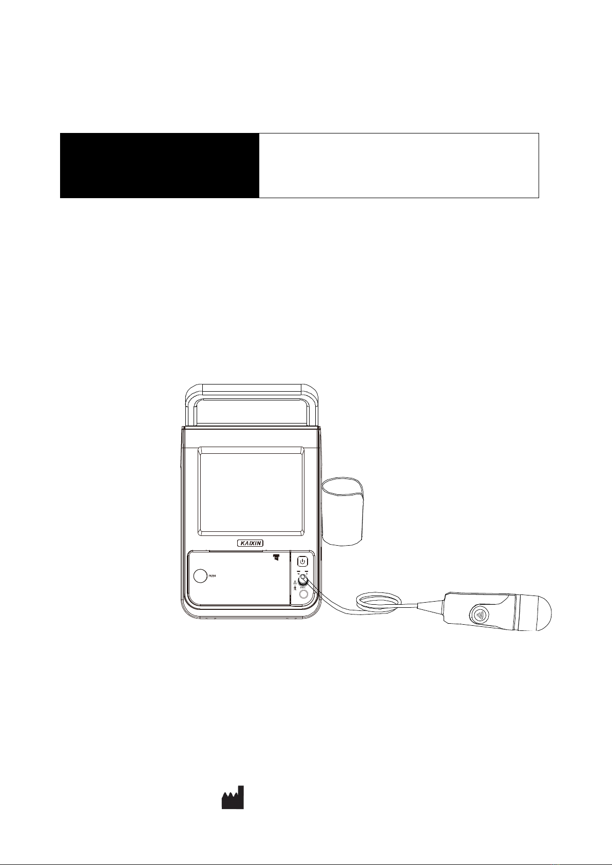
3.1 Structure composition of the instrument……………………………………………………3
3.2 Components name……………………………………………………………………………3
3.3 Parts of the probe………………………………………………………………………..3
3.4 Function keys description…………………………………………………………………..3
Chapter Four System Configuration……………………………………………………………5
Chapter Five Operation Condition………………………………………………………………5
Chapter Six System Installation and Check…………………………………….……………6
6.1 System placement……………………………………………………………………………7
6.2 Probe bracket installation……………………………………………………………………7
6.3 Connecting and disconnecting the probe……………………………………………………7
6.4 Connecting the foot switch…………………………………………………………………8
6.5 Install/Remove the battery…………………………………………………………………8
6.6 Connection to power…………………………………………………………………………8
6.7 Use the touch screen………………………………………………………………………9
6.8 Ultrasonic probe check before and after operation…………………………………………9
6.9 Main unit check before and after operation………………………………………………9
6.10 Reset………………………………………………………………………………………10
Chapter Seven Work Main Interface…………………………………………………………11
7.1 Work main interface………………………………………………………………………11
7.2 Title information region…………………………………………………………………11
7.3 Image and data region…………………………………………………………………11
7.4 Menu region…………………………………………………………………………………12
Chapter Eight System Preset…………………………………………………………………13
8.1 Basic settings………………………………………………………………………………13
Chapter Nine Functional Operation…………………………………………………………..15
9.1 Startup and Shutdown……………………………………………………………………15
9.2 Input patient information………………………………………………………………15
9.3 Save data…………………………………………………………………………………15
9.4 Read data…………………………………………………………………………………16
9.5 Thermal print……………………………………………………………………………17
Chapter Ten Bladder volume measurement……………………………………………………18
10.1 Scanning and positioning bladder………………………………………………………18
10.2 Operation processes………………………………………………………………………19
10.3 Manual contour……………………………………………………………………………20
Chapter Eleven Principle of Acoustic Power…………………………………………………21
Chapter Twelve System Maintenance…………………………………………………………22
12.1 Inspection and verification by users………………………………………………………22
12.1.1 Probe general inspection…………………………………………………………………22
12.1.2 Power-on verification……………………………………………………………………22
12.2 Maintenance by users……………………………………………………………………22

Bladder Volume Tester User’s Manual V1.08
12.2.1 System cleaning and disinfection…………………………………………………………22
12.2.2 Clean the probe socket……………………………………………………………………24
12.2.3 Clean the touch screen……………………………………………………………………24
12.2.4 Clean the foot switch……………………………………………………………………24
12.2.5 Clean the shell and probe bracket………………………………………………………24
12.2.6 Clean the thermal printer…………………………………………………………………24
12.3 Replacement of accessories and consumables……………………………………………24
12.3.1 Replace the thermal paper………………………………………………………………24
12.3.2 Replace the battery………………………………………………………………………25
12.3.3 Replace the probe, foot switch, power adapter and power supply cord, fuse…………25
12.4 Use and maintenance for the rechargeable battery………………………………………26
12.5 Troubleshooting…………………………………………………………………………27
12.6 Periodic Safety Checks…………………………………………………………………27
12.7 Essential Performance Checks……………………………………………………………28
Chapter Thirteen Storage and Transportation………………………………………………29
Chapter Fourteen Standard Compliance………………………………………………………29
Chapter Fifteen Safety Classification…………………………………………………………30
Chapter Sixteen Guidance and Manufacturer’s Declaration………………………………31
Appendix A System Block Diagram……………………………………………………………34
Appendix B Acoustic Output Data Disclosure…………………………………………………35

Bladder Volume Tester User’s Manual V1.08
- 1 -
Chapter One Overview
1.1 Introduction
BVT01 bladder volume tester is composed of main unit, probe, power adapter, etc., which is used to
non-invasively measure bladder volume with ultrasound principle. It is used to assess urinary retention and
urinary incontinence, and given the timing of implement an objective clinical catheterization to reduce the
catheterizing frequency and reduce the risk of urinary tract infections. But also by measuring the amount
of residual urine volume after voiding, evaluate the therapeutic effect of certain drugs and treatment for
urinary system diseases.
BVT01 bladder volume tester uses 2.5MHz ultrasound to mechanical sector scanning, identify the
reflected wave of the front and rear wall of the bladder to obtain the cross-sectional area of the bladder;
again through 15°intervals to automatically transform the scanning plane, based on the areas of 12
reference plane to calculate the bladder volume with ellipsoid integration.
To improve the accuracy of the operation and measurement, the screen displays the B-mode image of
section bladder and the projection of bladder; it is convenient for doctors to check the location and
determine the measurement results.
The expected service life of BVT01 bladder volume tester is 6 years.
BVT01 measurement accuracy must meet the following indicators: Urine volume display resolution
is 1mL. When urine volume is within 20mL~99mL, the measurement error is ±15mL; urine volume is
within 100mL~999mL, the measurement error is ±15%.
In a typical commercial or hospital environment, the use of instrument depends on the following
essential performance:
1. Electromagnetic disturbance does not make the instrument generate artifacts or distortion in an
image or error of a displayed numerical value and not alter the diagnosis.
2. Electromagnetic disturbance does not make the instrument generate the display of incorrect
numerical values associated with the diagnosis to be performed.
3. Electromagnetic disturbance does not make the instrument generate the production of unintended
or excessive ultrasound output.
4. Electromagnetic disturbance does not make the instrument generate the production of unintended
or excessive transducer assembly surface temperature.
1.2 Intended Use
BVT01 bladder volume tester projects ultrasound energy through the lower abdomen of the patient to
obtain images of the bladder which is used to calculate bladder volume noninvasively. The BVT01 bladder
volume tester is intended to be used onlyby qualified medical professionals.
Contraindications: The equipment is not suitable for fetal use or pregnant patients, patients with
ascites, patients with open or damaged skin, wounds in the suprapubic region.
Warning:This equipment cannot be used at home.
Attention: For patients with hypertrophy of the prostate, space occupying disease or
scars, there is a risk of producing a result exceeding the given accuracy range.
Warning:This equipment cannot be used to treat.

Bladder Volume Tester User’s Manual V1.08
- 2 -
Chapter Two Technical Specifications
2.1 Technical data
1. Monitor: 5.7” LED
2.Adapter rating: 100-240V~, 1.2-0.6A, 50-60Hz
3. Output of adapter: DC12.8V 3.0A
4. Main device rating: DC12.8V 3.0A
5. Main Unit Size: approx. 205 * 168 * 165 (mm, L * W * H)
6.Weight of main unit: approx. 1.7kg (excluding accessories)
2.2 Primary functions
1. System preset function: hospital name, date, date format and time.
2. Displaybasic information: hospital name, patient information (name, ID, age), date and time.
3. Patient information input function.
4. Screen saver time can be set.
5. Select the patient type.
6. Measurement information store function.
7. Urine volume measurement function.
8. Manually marking function.
9. USB disk can be encrypted to protect patient privacy.
10. Support language selection.
11. Thermal printing for ultrasound images and measurement results.
12. Displaybattery status indicator and lowbattery reminder function.
2.3 Technical index
1
Probe frequency, MHz
2.5
2
Urine volume display resolution, mL
1mL
3
Urine volume measurement range, mL
20mL~999mL
4
Urine volume measurement accuracy, mL
20mL~99mL
measurement error: ±15mL
100mL~999 mL
measurement error: ±15%

Bladder Volume Tester User’s Manual V1.08
- 3 -
Chapter Three System Outline
3.1 Structure composition of the instrument
BVT01 bladder volume tester is composed of main unit, probe, power adapter, etc.
3.2 Components name
Fig. BVT01 sketch map
3.3 Parts of the probe
Fig. Parts name of 2.5MHz probe
Name
Function
(1) Probe connector
To connect the probe to ultrasonic diagnostic system.
(2) Cable
To connect the probe to the probe connector.
(3) Scanning key
Press this keyto start urine volume measurement.
(4)Acoustic lens
Usemechanical methodsso thatthesoundbeamtransmittedbythe
transducercan sectorscanningforacertainangle.
3.4 Function keys description
SN.
Key symbol
Key name
Key function
1
System preset
Touch the key to enter system setting interface;
2
New patient
·Access to the new patient module;
·Input the information and data for a new
patient;
3
Scanning
In the power-on state, touch the keyto start
two-dimensional scan, touch this keyagain to
start the three-dimensional scan.

Bladder Volume Tester User’s Manual V1.08
- 4 -
4
Read data
Touch the key to open data file;
5
Save data
Touch the key to save data file;
6
Print
Print various measurement images/data;
7
and
Image
selection keys
In main interface, touch the keys to select the
desired left or right image;
8
, , ,
,
Patient type
key
In the two-dimensional scan state, repeatedly
touch this key to switch the desired patient
type, such as male, female, female with
hysterectomy, obesity and child;
9
and
Selection keys
·In the open file state, touch the key to select
the desired file;
·In the manual marking state, touch the key
to select the desired manual contour image;
10
Manual
contour key
Touch the key to manually draw the outline of
bladder;
11
Undo
Touch the key to revoke the last manual
mark operations;
12
Clear
In the manual contour process, touch the key to
clear all manual contour operations;
13
Main
Touch the key to return to main interface;
14
Copy to U disk
Touch the key to copy data files to U disk;
15
Exit
Touch the key to exit data file interface and
return to main interface;
16
OK
OK
Touch the key to carry out confirm function;
17
Cancel
Cancel
Touch the key to cancel operation;
18
Others
Numeric keys,
Letter keys
Numbers or letters to be used for text input.

Bladder Volume Tester User’s Manual V1.08
- 5 -
Chapter Four System Configuration
4.1 Typical configuration
1. Main unit 1 unit 2. 2.5MHz probe 1 pc
3. Power adapter 1 pc 4. Internal battery 1 pc
5. Touch pen 2 pcs
4.2 Optional parts
1. Battery 2. Foot switch 3. Charger
4. Verification cup 5. Glasses cloth
Chapter Five Operation Condition
5.1 Power supply
Adapter rating: 100-240V~, 1.2-0.6A, 50-60Hz
Adapter model: BJE01-40-001M
Output of adapter: DC12.8V 3.0A
Main device rating: DC12.8V 3.0A
5.2 Operation Environment
Ambient temperature: 5℃-40℃
Relative humidity: 30%-75% (without condensation)
Atmospheric pressure: 800hPa-1060hPa
Altitude: < 2000 m
Overvoltage: Overvoltage CategoryⅡ
Pollution degree: 2
5.3 Storage and Transport
Ambient temperature: -30℃-55℃
Relative humidity: 10%-93% (without condensation)
Atmospheric pressure: 500hPa-1060hPa
Attention:The mains voltage is varies with different countries or regions.
Danger: Do not use this equipment where flammable gas (such as anesthetic gas,
oxygen or hydrogen) or flammable liquid (such as alcohol) are present. Failure to do so
may result in explosion.
Warning: Using radio transmitting equipment nearby the system may interfere with
the normal operation of the system. Prohibited carry or use of devices that can generate
radio waves within the room installed this system, such as cell phones, radio transceivers
and wireless remote control toys.
Attention:System should be avoided using in following environments:
1. Splash 2. Moist 3. Rain 4. Thunderstorm weather
5. No ventilation 6. Dust 7. Close to heat source 8. Direct sunlight
9. Dramatic temperature change 10. Chemical medicines 11. Poisonous gas
12. Corrosivegas 13. Strong shock 14. Strong electromagnetic field (e.g. MRI)
15. Radiation (e.g. X-ray, CT) 16. Defibrillators orshort wave therapy equipment
Warning: AC/DC adapter is as a part of the equipment, please only use theAC/DC
adapterprovided by manufacturer.
Warning: Avoid using this equipment with high-frequency electric knife,
high-frequency therapy equipment or defibrillators and otherelectronic devices, ormay
an electric shock occur to the patient.

Bladder Volume Tester User’s Manual V1.08
- 6 -
Chapter Six System Installation and Check
Warning:
1. All plugs of instruments of this system shall be connected into the power socket with
protectively earth on the wall and the socket must meet the requirement of power rating
of instrument. Use of multiple portable socket-outlets may affect protective earth to
make leakage currents exceed the safety requirements.
2. Please follow the correct electrical connections method to connect the power supply and
earth, otherwise there will be danger of electric shock. Do not connect the grounding wire
to anygas pipe orwater pipe, or it may cause bad grounding and dangerof explosion.
3. This equipment is not waterproof, not use this equipment in place where liquid may into
the interior of the equipment. Never pour any liquid on the equipment; otherwise there
will be danger of electric shock or cause equipment damage. If accidentally spill liquid
on the equipment, turn off thepower immediately and contact yourlocal representative.
4. Prohibit the live parts of the equipment or other devices (such as various signal input
and output ports, etc.) contact with the patient, if this equipment orotherequipment has
failure, the patient will have danger of electric shock.
5. Additional equipment connected to the medical electrical equipment must comply with
the respective IEC or ISO standards (e.g. IEC60950 for data processing equipment).
Furthermore all configurations shall comply with the requirements for medical electrical
systems (see IEC 60601-1-1 or clause 16 of IEC60601-1 3rd, respectively). Anybody
connecting additional equipment to medical electrical equipment configures a medical
system and is therefore responsible that the system complies with the requirements for
medical electrical systems. Attention is drawn to the fact that local laws take priority
over the above mentioned requirements. If in doubt, consult your local representative or
the technical service department.
6. If the integrity of the external protective conductor in the installation or its arrangement
is in doubt, equipment shall be operated from its internal electrical power source.
Warning: To avoid the risk of electric shock, this equipment must onlybe connected to a
supply mains with protective earth.
Warning:
1. When instrument works abnormally, do stop working, turn off the powerand check the
reason, then contacts the Kaixin Company about it.
2. Turn off powerand pullout of the plug fromsocket after each operation.
3. Itisforbidden to drag and press the power and probe cables emphatically;regularly
inspect whetherthere is spilt and bareness,if there is the phenomena like this; turn off
power supply immediately, stopusing it and change it fornew one.
4. It is forbidden to load and unload theprobe ormove the instrument in galvanic to avoid
danger of safety.
5. Pull out of the plug from socket after operation in thunderstorm weather to avoid the
instrument being damaged by lightening.
6. If the temperature changes greatly in short time will cause vaporrecovery inside of
instrument, the case may damage the instrument.
7. The instrument is turned off completely only by disconnecting the powersupply from
the wall socket.
Warning:The power adapter, power supply cord, probes, foot switch, battery and charger
as described in this section are replaced by operator. But these parts must be provided by
KAIXIN orhis authorized supplier.

Bladder Volume Tester User’s Manual V1.08
- 7 -
6.1 System placement
Please carefully read through and fully understand the safety cautions before moving and placing the
system.
1. Unpack the instrument case and check the goods for its completeness according to the packing list
furnished.
2. Place the instrument ona stable and leveled position.
3. Leave adequate space of 20 centimeters as minimum from rear, left and right side of the instrument.
6.2 Probe bracket installation
The probe bracket should be mounted on the both sides of the main unit.
6.3 Connecting and disconnecting the probe
Attention: Adequate space from rear, left and right side of the machine shall be reserved,
orthe machine may malfunction under excessiveheat inside the enclosure.
Attention:
1. Usually the probe should be placed within theprobe bracket, not on the desktopor
other support to avoid the drop.
2. Probe is a critical,precision part, do not stress, impact, or fall it. Do notpull orwring
wound probe cable.
3.Turn off the ultrasonic system before disconnecting the probe. Disconnecting the probe
with system power on may damage the system or probe.
4. Before disconnecting the probe,place the probe on the probe bracket in order to
prevent the probe may not be damaged by unexpected fall.
5. Care should be taken when using the probe normally and itshould behandled gently to
avoid mechanical damage to the transducerassembly.
6. Use a qualified coupling gel to keep the probe dry. If the unqualified coupling gel is used
orthe probe surface is not cleaned in time, the lens of theprobe surface may be
corroded and damaged.The surface of the probe may be cleaned with a soft cloth. Do
not scrubwith hard paper.
7. Repeat available machine time should be more than 5 minutes to avoid turn on/off
power supply in short time.
Warning:
1. Do notuse the probe not provided by ourcompany, otherwise the equipment and the
probe will cause damage, and may cause fire in extreme cases.
2. Check the probe and connecting cable afterdiagnostic operation. Use of defective probe
may cause electric shock.
3. Do not strike orhitthe probe; the impact may damage the crystal inside the probe. Using
the damaged probe may cause electricshockto thepatient.
4. Unauthorized disassembly of the probe shall be prohibited as it may cause electric
shock.
5. Forthe depth of immersion during disinfection, please refer to “Probe regular
disinfection” in Chapter12.2.1; Failure to disinfect as required can cause internal short
circuits and burnout of the board.
Danger:Use togetherwith flammable anaesthetic, it may result in explosion.
Attention: Probe is highly sensitive to shake, be used with caution. About probe’s use
and cleaning, the details see the relevant sections.

Bladder Volume Tester User’s Manual V1.08
- 8 -
6.3.1 Connecting the probe
The probe is inserted the “PROBE”socket on the panel.
6.3.2 Disconnecting the probe
Shutdown the system; hold the red marked part near the probe connector, and pull out the ultrasound
probe connector vertically.
6.4 Connecting the foot switch
Shutdown the system; insert the plug of foot-switch into the “FOOT SW” socket on the back of the
main unit.
6.5 Install/Remove the battery
1. Install the battery
Pull out the ribbon to make it a natural droop, push the batteryin the battery storage and tidyup the
ribbon, finallycover the “Battery cover”.
2. Remove the battery
Hold down the battery-cover buckles above, and remove the battery cover, pull the ribbon and take
out the battery.
Fig. Install, Remove the battery
6.6 Connection to power
1. Connectto the poweradapter
Insert the output plug of adapter into power input interface, which is on the back of main unit.
2. Connectto the main power supply
Insert the power plug (jack) furnished with the machine into power input socket of the power adapter,
the other end to the mains socket-outlet. The instrument uses three-core power line. It connects with
the protective earth line when power plug inserts into the standard power socket.
Warning: Before connecting or using the probe, make sure that the probe, connecting
cable and connector are in normal condition (free of cracks or drop). Use of defective
probe may cause electric shock.
Attention:The red mark of connector should be alignedwith the red mark on the socket
when inserting the probe.
Attention:Disconnecting the probe, do not pull the probe cableto prevent cabledamage.
Attention:The waterproof grade of foot switch is IPX1.

Bladder Volume Tester User’s Manual V1.08
- 9 -
6.7 Use the touch screen
The touch screen provided with the equipment is a highly sensitive device which enables selections to
be made and recorded on screen. On-screen selections should only be made by gently using a finger or the
provided touchpen. Do not use a pencil, pen, or other sharp object to touch screen.
6.8 Ultrasonic probe check before and after operation
Before and after ultrasonic diagnosis to check if there are any exceptionally on the surface of the
probe or cable jacket, such as peeling, cracks, bulge, or if the acoustic lens is reliable, disinfected or
cleaned.
6.9 Main unit check before and after operation
6.9.1 Inspection before start-up
Check the following itemsbefore starting the machine:
1.The temperature, humidity and atmospheric pressure shall meet the requirements of operation
condition.
2. No condensation occurs.
3. No distortion, damage or contamination on system and peripheral. Clean the parts as specified in
relevant sections, if the contaminant is present.
4. Check the touch screen and enclosure to ensure they are in good working condition and free of
abnormity(such as cracks and loosened screws).
5. No damage on cables (e.g. power cable, etc.), and not loose the connection.
6. Check probe and its connections to ensure they are free of abnormity (such as scuffing, drop-off or
contamination). If the contaminant is present, clean, disinfect the contaminated objects as specified
in relevant sections.
7. No barriers around the intake of equipment.
8. See to it that probe has been cleaned, disinfected; else dispose it as specifiedin relevant sections.
9. Examine that the foot switch functions properly is placed in a convenient location, and that the cable
is free from becoming entangled.
10. Check all the ports of the machine for possible damage or blockage.
11. Clean the field and environment.
6.9.2 Inspection afterstart-up
Check the following items after starting the machine:
1. No abnormal voice, strange smell and overheating appear.
2. Check the machine to ensure a normal start-up: The power indication light is on and startup picture is
shown on the screen, and then the machine enters later.
3. Check the acoustic lens for abnormal heat when the probe is in use. This can be done by hand
touching the probe to feel the temperature of the lens.
4. Check the image to ensure trouble-free display(e.g. no excessive noise or flicker).
5. Check the instrument to ensure that the phenomenon of local high temperature will not appear.
Warning:
1. Adapter has no switch. APPLIANCE COUPLER or MAINS PLUG is used as the
intended disconnection device from the supply mains. Do not position the
EQUIPMENT the place where it is difficult to operate the disconnection device.
2. AC/DC adapter is as a part of the equipment, please only use the AC/DC adapter
provided byKaixin Company.
3. To avoid damaging power adapter or harming people by unexpected fallen, make sure
the power adapteris placed on the leveled desk.
4.The operatormust not touch signal input/output and patient simultaneously.
Attention: Care should be taken when using the equipment so that excessive force is not
applied to the touch screen, as itis may become permanently damaged.

Bladder Volume Tester User’s Manual V1.08
- 10 -
6.10 Reset
In case of abnormal screen display or no-working for system operation, turn off the power and try to
restart the system.
Attention:If the overheat acoustic lens is placed on the patient’s skin, heat injury may occur.
Attention: Thoroughly clean the coupling gel on the probe surface each time after
ultrasonic operation, or the coupling gel may become hardened on the acoustic lens of the
probe, deteriorating quality of image.
Warning: Only use the coupling gel that in accordance with MDD regulations.

Bladder Volume Tester User’s Manual V1.08
- 11 -
Chapter Seven Work Main Interface
7.1 Work main interface
Press the button on the front panel, turn on the machine, the touch screen displays the work main
interface, as follows:
Fig. Work main interface
Work main interface shows the ultrasonic images, various data and the corresponding operation
menus, etc. Main interface is divided into title information region, image and data region, and menu
region.
7.2 Title information region
It displays the hospital name, patient information (name, ID, age), battery status indicator, etc.
1. Hospital name
Display hospital name. Hospital name can be edited and modified in the “System/Basic Settings”.
2. Patient information
Display the patient’s name, ID and age. In the module of new patient, input or edit the name, ID and
age for the current patient.
3. Battery status indicator
Display the remaining battery power level.The battery status indicator is shown on the top right of
screen.
: Indicates a fully charged battery;
: Indicates a battery 75% charged;
: Indicates a battery 50% charged;
: Indicates a battery almost depleted and needs to be recharged.
7.3 Image and data region

Bladder Volume Tester User’s Manual V1.08
- 12 -
The image and data region is divided into left part and right part.
The upper part of left displays patient type and image selection keys ( / ). Patient types are
divided into male, female, female with hysterectomy, obesity and child. Touch left or right image to
enter manual contour interface, for individual complex images having large error, the doctor may
choose manual contour function.
The lower part of left displays B-mode images of bladder section. Sectional images of bladder
have a total of 12 frames, which are divided into six groups, each group consisting of two
orthogonal images; you can switch the images by touching the keys and at the top of images.
The six groups of orthogonal images are generated by the scanning planes automatically changed by
15°intervals, the number of image frames corresponding to an image is shown above each image;
The upper left corner of each image displays the scanning position of bladder, respectively
are , , , , , .
The right part displays the bladder projection generated by completed scanning each time,
which can be used to locate the position of bladder. The projection position is closer to the center of
the coordinate; the measurement results will be more accurate. The machine can simultaneously
display four groups of measurements, it is convenient for doctors to compare, “”indicates the
current measurement result.
7.4 Menu region
Menu region includes six function keys and displays the system date and time, etc.
1. System date and time
Display the current system date and time. The adjustment of date and time, as well as the format
of date can be edited and modified in the “System/Basic Settings”.
2. Six function keys
Six function keys respectively are system preset , patient information , scanning , open
data , save data and print .

Bladder Volume Tester User’s Manual V1.08
- 13 -
Chapter Eight System Preset
Touch『 』key, the system preset dialog box will be displayed on the screen, as below. In the
"About" interface, you can view the full version and release version of the software.
Min(0-100)
System
Hospital:
Date:
Format:
Time:
Screensaver:
Language:
Basic Settings About
20 14 Y 03 M 12 D
99
10 H 28 Min 45 S
Chinese English
YYYY/MM/DD
OK Cancel
1 2 3 4 5 6
7 8 9 0 - .
Bspace
Enter
Fig. System preset dialog box
8.1 Basic settings
Set hospital name
1. Touch the “Hospital” input box, andthen pop up the “CharInput”keyboard, inputthe hospital name;
Fig. Character input keyboard
2. If needs input Chinese,touch keyto switch Chinese and English(the key is active in the Chinese
version);
3. If needs revise, touch key to delete the previous character and retype;
4. Touch the「ENTER」key on the upper right side of keyboard when finished.
Date, the Format of date and Time
1. Touch the “Date”input box to confirm the cursor position, enter the “Year, Month, Day” using the
following digital keyboard;
2. Touch the “Format” drop-down menu and choosethe desired date format;
3. Touch the “Time” input box to confirm the cursor position, enter the “Hour, Minute, Second” using
the following digital keyboard;
Attention: In the system preset interface, the contents of all input are required, if empty,
touch “OK”key does not work. All parameters are entered, touch “OK”key to save the
parameters and exit the system preset; otherwise touch “Cancel”key to exit system preset
interface without saving the parameters.
Other manuals for BVT01
1
Table of contents
Other Kaixin Test Equipment manuals