HVTest HTFZ-HI User manual

1
Dear Client
Thank you for Purchasing our HTFZ-HI Arrester Discharge
Counter Calibrator. Please read the manual in detail prior to first
use, which will help you use the equipment skillfully.
Our aim is to improve and perfect the
company's products continually, so there may be
slight differences between your purchase equipment
and its instruction manual. You can find the changes
in the appendix. Sorry for the inconvenience. If you have further
questions, welcome to contact with our service department.
The input/output terminals and the test column
may bring voltage, when you plug/draw the test wire or
power outlet, they will cause electric spark. PLEASE
CAUTION RISK OF ELECTRICAL SHOCK!
Company Address:
T4,No. 41, High-tech 2 Road,East Lake High-tech Development Zone,
Wuhan
Sales Hotline: 86-27- 87457960
After Service Hotline:86-27- 87459656
Fax: 86-27- 87803129
E-mail: [email protected]
Website: www.hvtest.cc

2
SERIOUS COMMITMENT
All products of our company carry one year limited warranty
from the date of shipment. If any such product proves defective
during this warranty period we will maintain it for free. Meanwhile
we implement lifetime service. Except otherwise agreed by
contract.
SAFETY REQUIREMENTS
Please read the following safety precautions carefully to avoid
body injury and prevent the product or other relevant subassembly
to damage. In order to avoid possible danger, this product can only
be used within the prescribed scope.
Only qualified technician can carry out maintenance or repair
work.
--To avoid fire and personal injury:
Use Proper Power Cord
Only use the power wire supplied by the product or meet the
specification of this produce.
Connect and Disconnect Correctly
When the test wire is connected to the live terminal, please do
not connect or disconnect the test wire.
Grounding
The product is grounded through the power wire; besides, the
ground pole of the shell must be grounded. To prevent electric

3
shock, the grounding conductor must be connected to the ground.
Make sure the product has been grounded correctly before
connecting with the input/output port.
Pay Attention to the Ratings of All Terminals
To prevent the fire hazard or electric shock, please be care of
all ratings and labels/marks of this product. Before connecting,
please read the instruction manual to acquire information about the
ratings.
Do Not Operate without Covers
Do not operate this product when covers or panels removed.
Use Proper Fuse
Only use the fuse with type and rating specified for the product.
Avoid Touching Bare Circuit and Charged Metal
Do not touch the bare connection points and parts of energized
equipment.
Do Not Operate with Suspicious Failures
If you encounter operating failure, do not continue. Please
contact with our maintenance staff.
Do Not Operate in Wet/Damp Conditions.
Do Not Operate in Explosive Atmospheres.
Ensure Product Surfaces Clean and Dry.

4
-Security Terms
Warning: indicates that death or severe personal injury may
result if proper precautions are not taken
Caution: indicates that property damage may result if proper
precautions are not taken.

5
Contents
I Technique Parameters........................................................ 6
II Panel diagram...................................................................... 6
III Impulse test......................................................................... 7
IV Ammeter calibration..............................................................9
V Notes...................................................................................... 10
V. Packing List..........................................................................10

6
I Technique Parameters
The function of the Arrester Discharge Counter Calibrator is not only to record
the number of lightning strikes, but also to monitor the leakage current of the
arrester online.Our newly developed lightning arrester online monitor calibrator
is an instrument with both impact test and ammeter calibration functions.
Parameters:
Input voltage AC220V±10% 50Hz;DC12V
Impulse voltage 0-1600V Precision:2%±5V (Customized higher voltages
as required)
Impulse current >100A (8/20μS square wave)
Calibration current 0-10mA, ±2%±3 words
Instrument power consumption <30VA
Diemension 320×240×150mm3
II Panel diagram
输出:output 电压:Voltage 冲击试验:Impulse Test 电流调节:Current regulation

7
充电指示:Charging indicator
III Impulse test
1. Test principle
Figure 1 is circuit diagram of JS-type operating cycles counter. Figure 1 (a)
shows circuit diagram of JS-type operating cycles counter, also called
dual-valve plate structure. When the arrester operating, the discharge current
drop voltage through the valve R1, and charge capacitor C through the valve
R2, then C discharge to the inductance coil L of magnetic counter, let it rotate a
division and record one time. Changing the resistance values of R1 and R2, the
counter will have different sensitivity. Generally the minimum action current is
100A (8/20μs) impact current. Because there is some voltage drop on R1, and
these will increase residual voltage of arrester, the instrument is mainly used for
HV arresters above 40kV.
Fig 1 Circuit diagram for JS-type operating cycles counter
(a) JS-type (b) JS-8 type
R1, R2-nonlinear resistance C-Energy-storage capacitor
L-Counter coil D1-4 A silicon diode

8
Figure 1 (b) shows circuit diagram of JS-8 type operating cycles counter, it
is rectifier type structure. When the arrester operating, voltage drop on the valve
R1 charge capacitor C through full-wave rectifier, then C discharge to L of
electromagnetic counter and let it count. For this counter, the resistance value
of valve R1 is small (when at 10kA, the voltage drop is 1.1kV), current capacity
is larger (1200A square wave), the minimum action current is 100A (8 / 20μs)
impact current. JS-8 counter is suitable for 6.0 ~ 330kV arrester, JS-8A counter
can be used for 500kV arrester.
2. Inspection method for action and principle of counter
As bad seal, may there are moisture and water will enter operating cycles
counter during operating, which will make internal components corrode, further
counter cannot work properly, so the "regulations" require that this device
should be checked one a year. The two methods of on-site inspection counter
action are: capacitor release current method (DC&AC) and standard impulse
current method. Research indicates that standard impulse current method is
more reliable; the principle circuit diagram is shown in Figure 2.
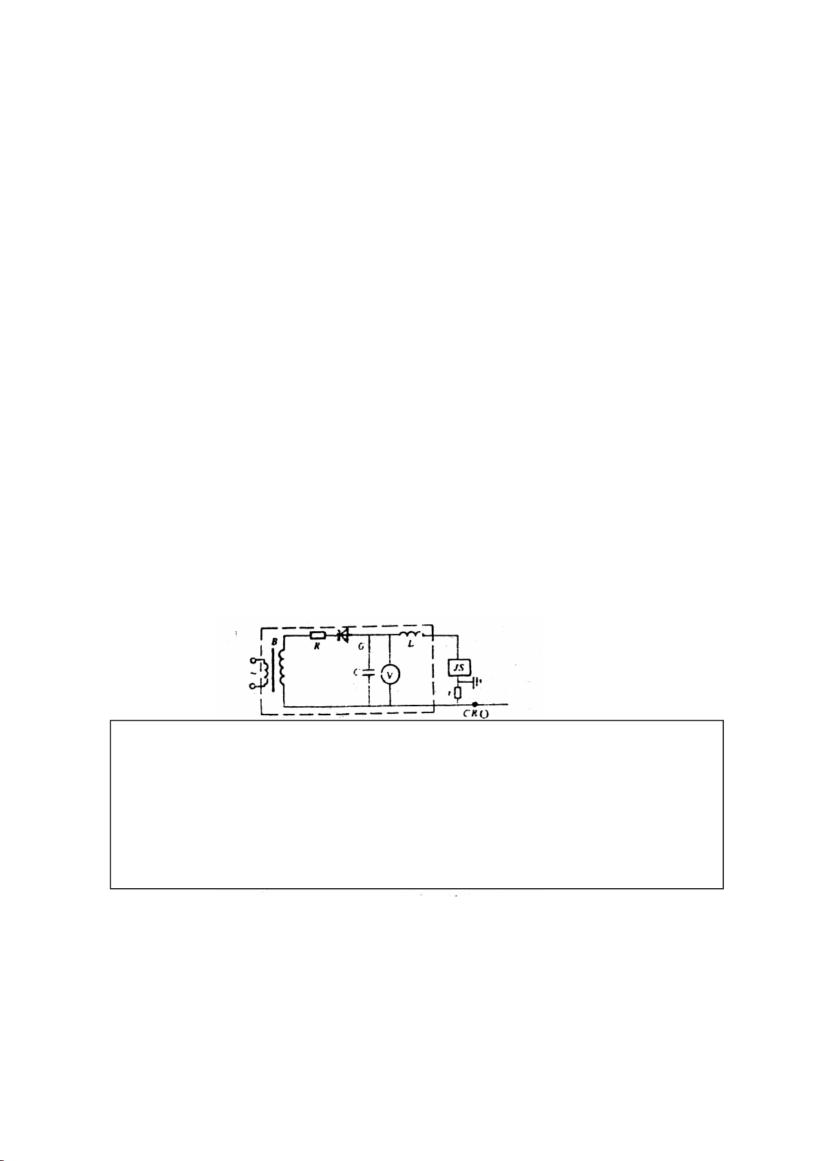
Let 8/20 μs, 100A impulse current waves generated by impulse current
generator act on operating cycles counter, if counter is functioning normally,
which indicating the instrument is well, otherwise it should be repaired. For
example, a power administration uses this method to test 27 counters, three of
them cannot act, the technician finds that the internal components are affected
Fig. 2 the principle circuit diagram for standard impulse current method
(Impulse current generator in the dashed box)
C---charging capacitor R---charging resistance L--- damped inductance
D---Silicon rectifier diode r---Current divider B---Test transformer
V---Electrostatic voltmeter CRO---high-voltage oscilloscope

9
with damp and damaged.
"Regulation" provides that continuously test for 3 to 5 times, each action
should be normal, each time interval should be not less than 30s. After test
logger should be set to zero.
3.Operation method
1. Let the output terminal of instrument connect to the two ends of arrester
counter (the connecting lead should be as short as possible), red terminal
connect to upper end, black terminal connect to earth terminal.
2. Well connect power cord (use DC power, need not connect power), then
check whether the equipment and wiring are correct, confirm all is ok, you
can start test.
3. Close power switch (power light glows), wait the voltage exceeds 600V,
you can start test (Rated voltage of instrument is 1600V; higher voltage can
also be customized according to user’s requirements).
4. Press “Test”key, output voltage will immediately drop, at this time you
can observe the action of counter.
5. For multiple tests, please wait output voltage exceeds 600V, then press
“Test”key and observe the action of counter.
6. After test, please immediately turn off power supply; remove the wiring
after output voltage has completely come back to zero.
7. If you pressing “Test”key, output voltage do not drop, you should turn
off power supply, wait voltage come back to zero, then check whether there
is a breakpoint on the circuit or the type of discharge counter is not suitable
for the specified technical specification type.
IV Ammeter calibration

10
Under the shutdown state of the instrument, the wiring mode is the same
as the impact test to form a circuit, after the wire is connected, press the
current and voltage switch, and then can start! At this time, the
instrument is in the state of electrical flow output.When checking, adjust the
current to adjust the potentiometer, compare the instrument dial indication
and the sample dial display, in order to determine whether the sample
current indication is correct or not! Suggestion: first carry out rough
correction, compare the accuracy of large scale, and then adjust the current
to within 2mA, for accurate verification, to determine the reliability of the
sample!
V Notes
1. Removing wiring, if the input voltage has not returned to zero, the
operator can not touch the non-insulated part of test leads to avoid injury.
2. The tested target cannot bring voltage.
3. If DC power has run down, please charge up the battery in time.
4. Under DC test, if the voltage cannot reach specified scale, please stop
using DC power and use AC power instead for test.
5. If the instrument not use for a long time, please charge up the battery
every two months, generally charging time is about 14 hours, until the "full"
indicator lights up.
V. Packing List

11
1. Instrument host
2. Power cord
3. Test Wire
4. Grounding wire
5. The instruction manual
1
1
2
1
1
6. Certificate
1
Table of contents
Other HVTest Test Equipment manuals

HVTest
HVTest HT2672 User manual

HVTest
HVTest TAG-8000 User manual

HVTest
HVTest HT2571B User manual

HVTest
HVTest HTYSZ-H User manual

HVTest
HVTest HTZZ-S10A User manual

HVTest
HVTest HTZZ-2A User manual

HVTest
HVTest HTFZ-III User manual

HVTest
HVTest HT5600 User manual

HVTest
HVTest HTYB-3H User manual

HVTest
HVTest HTZZ-5A User manual

HVTest
HVTest ETCR2000 User manual

HVTest
HVTest HTRG-H User manual

HVTest
HVTest HTJS-M User manual

HVTest
HVTest HT2671 User manual

HVTest
HVTest HTZZ-1A User manual

HVTest
HVTest HT2670 User manual

HVTest
HVTest HT-802 User manual

HVTest
HVTest HTYZL-H User manual

HVTest
HVTest HTYX-III User manual

HVTest
HVTest HT2533 User manual