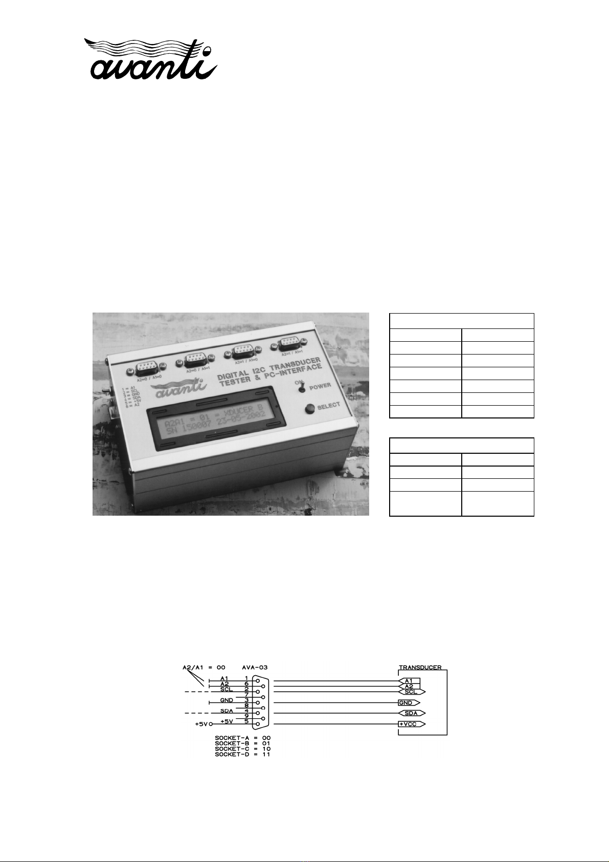
DIGITAL TRANSDUCER TESTER & PC-INTERFACE (AVA-03)
14-FEB-2022
PAGE 4 OF 12
© Avanti Elektronik Limited - (44) 01224-583132 - www.avanti.clara.net -
[email protected].
k dqdtst_32.docx
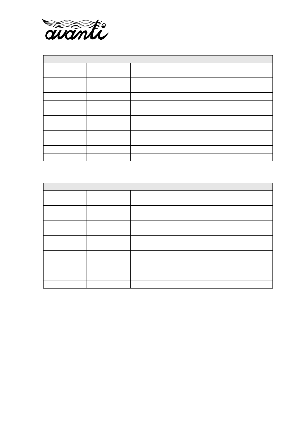
1: BAR-ABS/DEGC Absolute pressure is displayed in bar and temperature in °C
2: BAR-GAUGE/DEGC Gauge pressure (see paragraph 6 1) is displayed in bar and temperature in °C
3: PSI-ABS/DEGC Absolute pressure is displayed in psi and temperature in °C
This is the default setup
4: PSI-ABS/DEGF Absolute pressure is displayed in psi and temperature in °F
5: PSI-GAUGE/DEGC Gauge pressure (see paragraph 6 1) is displayed in psi and temperature in °C
6: PSI-GAUGE/DEGF Gauge pressure (see paragraph 6 1) is displayed in psi and temperature in °F
7: BAR-ABS/DEGF Absolute pressure is displayed in bar and temperature in °F
8: BAR-GAUGE/DEGF Gauge pressure (see paragraph 6 1) is displayed in bar and temperature in °F
9: PSI/DEGC/DUAL-P Absolute pressure is displayed in psi and temperature in °C Initial screen
shows pressure values of 2 transducers together (see paragraph 6 2)
10: PSI/DEGF/DUAL-P Absolute pressure is displayed in psi and temperature in °F Initial screen
shows pressure values of 2 transducers together (see paragraph 6 2)
11: BAR/DEGC/DUAL-P Absolute pressure is displayed in bar and temperature in °C Initial screen
shows pressure values of 2 transducers together (see paragraph 6 2)
12: BAR/DEGF/DUAL-P Absolute pressure is displayed in bar and temperature in °F Initial screen
shows pressure values of 2 transducers together (see paragraph 6 2)
Once the desired configuration is shown on the screen, the tester is sim ly switched off.
The tester remembers and a lies this configuration when owered u again in the normal
way.
6.1 ABSOLUTE / GAUGE PRESSURE
The AVA-03 I²C Transducer Tester can be configured to dis lay absolute or gauge
ressure (see aragra h 5 above). When gauge ressure is selected, the sequence of screens
is as follows:
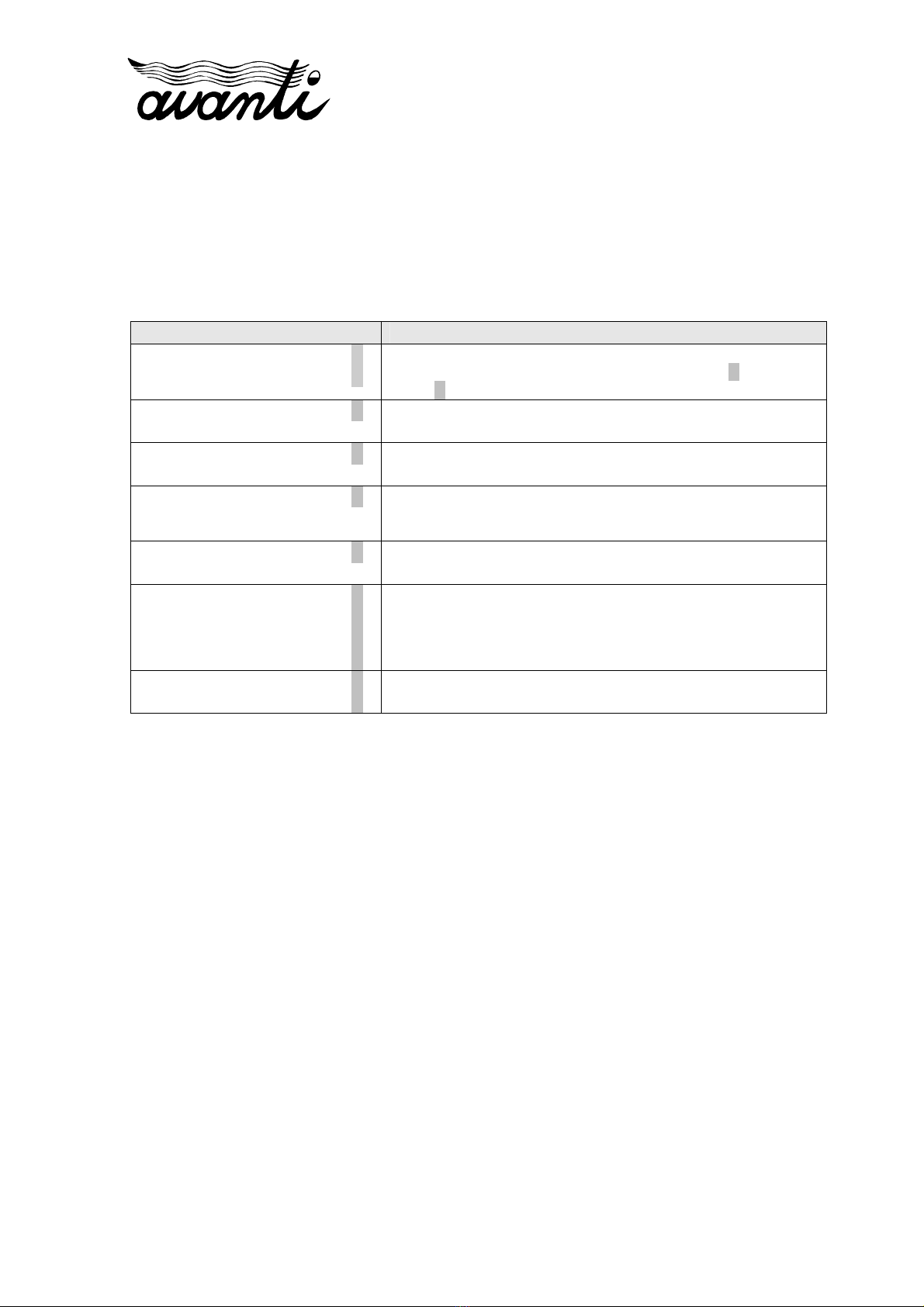
LCD Dis lay: Descri tion:
PRESS BUTTON TO STEP
THROUGH OPTIONS
1 Start-up Screen
A2A1 = 00 = XDUCER A
SN 000123 04-12-2007
2 Status Screen
RAW-P = 0x00B60B61 A
RAW-T = 0x01C71C72
3 Raw Values
PF = 20000.000 Hz A
TF = 50000.000 Hz
4 Equivalent Frequencies
ATMOSPHERIC PRES: A
P = 14.500 si
5 Tare Screen: When the button is pressed again, the last pressure
value displayed is captured and applied as an atmospheric offset
until the unit is powered down
P = 0.000 sig A
T = 25.000 degC
6 Calculated pressure / temperature with atmospheric offset of
-14 5 psi applied
The tare screen is shown once only after ower-u . The atmos heric offset remains valid
until the tester is owered down. To change the atmos heric offset, the tester must be
switched off and on again. In case of multi le transducers, the transducer with the lowest
I²C address is used to determine the atmos heric offset. The same offset is then a lied to
all transducers.