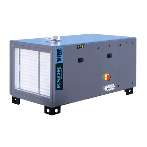
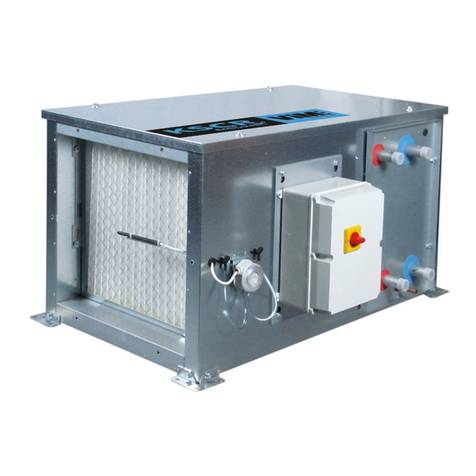
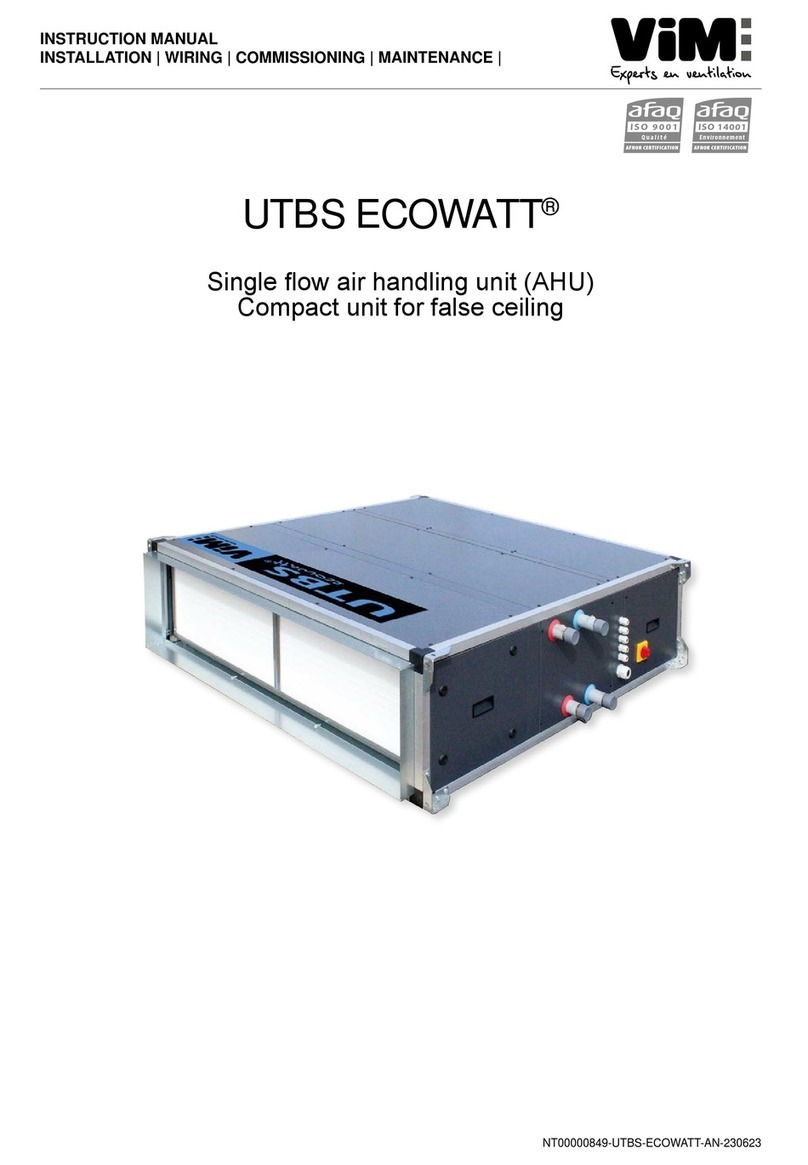
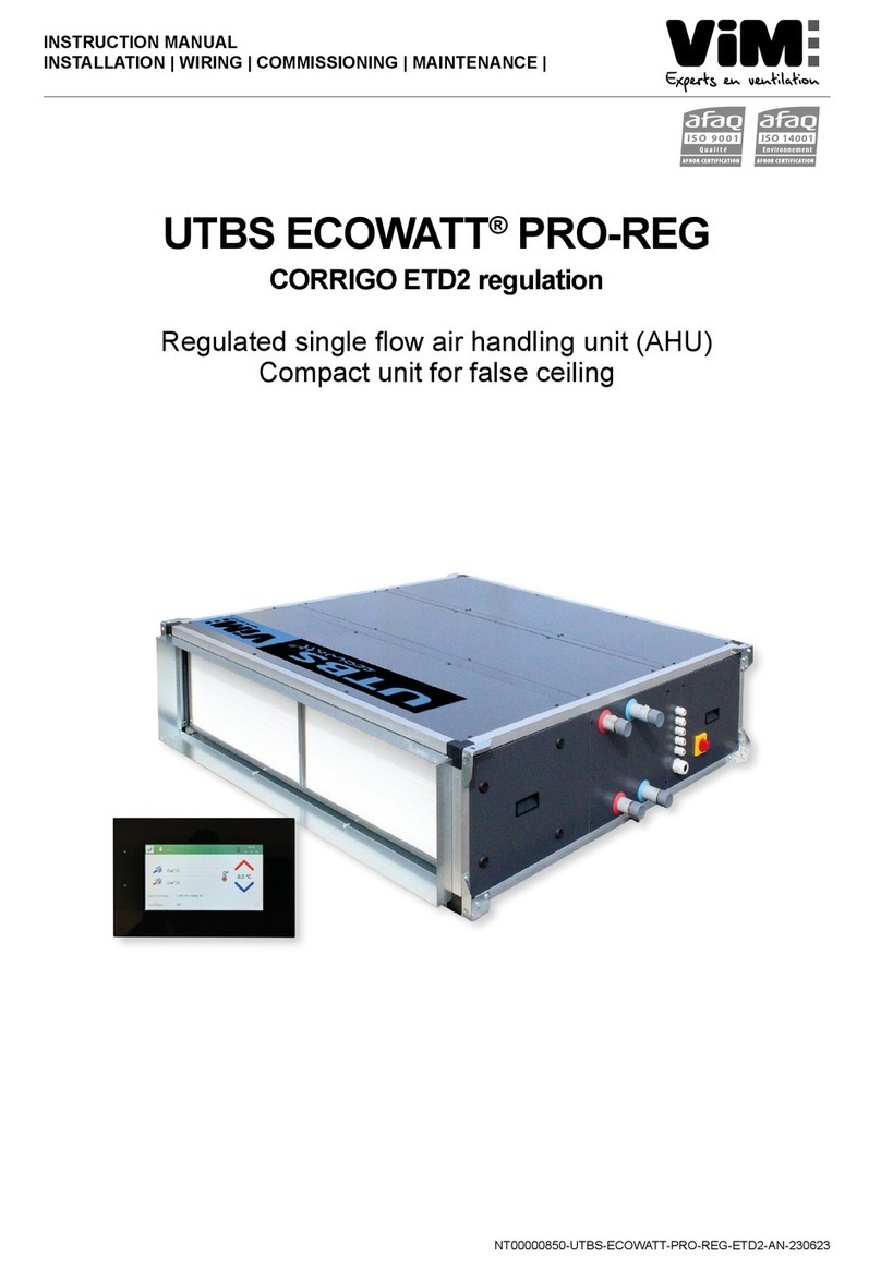
ViM CAD O Integral User manual

NT-50897201-CAD-O-INTEGRAL-ETD2-AN-230123
INSTRUCTION MANUAL
INSTALLATION | WIRING | COMMISSIONING | MAINTENANCE |
AFNOR CERTIFICATION
ISO 14001
Environnement
AFNOR CERTIFICATION
ISO 9001
Qualité
CAD O Integral
Air Handling Unit with Rotating Heat Exchanger

NT-50897201-CAD-O-INTEGRAL-ETD2-AN-2301232/96
ENGLISH
INDEX
1. GENERAL........................................................................................................................................... 3
1.1 Warnings .................................................................................................................................. 3
1.2 Safety instructions .................................................................................................................... 4
1.3 Acceptance – Storage .............................................................................................................. 4
1.4 Warranty ................................................................................................................................... 4
2. PRODUCT RANGE PRESENTATION................................................................................................ 5
2.1 Range....................................................................................................................................... 5
2.2 Main components ..................................................................................................................... 6
3. INSTALLATION .................................................................................................................................11
.............................................................................................11
3.2 Dimensions and weight .......................................................................................................... 12
3.3 Handling ................................................................................................................................. 20
3.4 Placement and attachment point ........................................................................................... 21
.......................................................................... 25
................................... 28
4. HYDRAULIC AND FLUID CONNECTION ....................................................................................... 29
4.1 Water coils connection ........................................................................................................... 29
................................................................................................................... 31
4.3 Connection of direct expansion coils...................................................................................... 32
5. AIR DUCT CONNECTION................................................................................................................ 32
5.1 Ducts connection.................................................................................................................... 32
5.2 Accessories connection.......................................................................................................... 33
6. ELECTRIC CONNECTION............................................................................................................... 36
6.1 Electrical data......................................................................................................................... 36
.................................................................. 40
6.3 Controller CORRIGO - Technical data ................................................................................... 41
6.4 Display (ETD2) control connection......................................................................................... 42
6.5 External components connection drawings (examples) ......................................................... 45
6.6 Synoptic installation diagrams (examples) ............................................................................. 53
7. COMMISSIONING ............................................................................................................................ 55
8. CONTROL - FUNCTIONS / PARAMETERS .................................................................................... 56
.................................................................................................................. 57
8.2 Temperature control................................................................................................................ 59
8.3 Special case: temperature control with EX direct expansion coil ........................................... 61
................................................................... 61
8.5 Hot water coil frost protection................................................................................................. 63
................................................................................................................. 64
............................................................................................................. 65
................................................................................................... 65
8.9 Clock and time programming.................................................................................................. 65
9. ALARMS AND FAULTS ................................................................................................................... 66
10. USING AND CONFIGURING THE CONTROL VIA THE TOUCH DISPLAY ETD2 ......................... 67
10.1 Presentation of the ETD2 touch display ................................................................................. 67
...................................................................................... 71
.............................................................................................. 73
10.4 Settings common to all fan operating modes ......................................................................... 74
11. ADVANCED SETTINGS VIA ETD2 TOUCH DISPLAY.................................................................... 75
11.1 Schedule programming .......................................................................................................... 75
11.2 Communication protocol settings ........................................................................................... 77
11.3 Backup - Restore.................................................................................................................... 78
.................................................................................................................. 79
12. COMMUNICATION ........................................................................................................................... 83
.................... 83
12.2 Connection to a Centralized Technical Management (BMS) in BACnet language ................. 85
12.3 Resetting the CORRIGO controller ........................................................................................ 86
NT-50897201-CAD-O-INTEGRAL-ETD2-AN-2301233/96
ENGLISH
1. GENERAL
1.1 Warnings
This product was manufactured according to rigorous technical safety rules in compliance with DC stan-
Before installing and using this product, carefully read these instructions, which contain important indica-
this product.
The installation of this product (implementation, connections, commissioning, maintenance) and all other
-
dards and safety regulations in force.
-
• Indoor installation (recommended) or outdoor installation with accessories.
•
•
•
•
•
•
13. MAINTENANCE................................................................................................................................ 88
13.1 Prior precautions .................................................................................................................... 88
13.2 Maintenance frequency .......................................................................................................... 88
...................................................... 89
................................................ 90
............................................................................................. 90
13.6 Electric heater maintenance / replacement ............................................................................ 90
13.7 Maintenance / replacement of the water coil.......................................................................... 91
...................................................................................... 91
13.9 List of main spare parts .......................................................................................................... 91
14. WASTE MANAGEMENT .................................................................................................................. 94
14.1 Treatment of Packaging and non-hazardous waste ............................................................... 94
14.2 Treatment of Professional WEEE........................................................................................... 94

NT-50897201-CAD-O-INTEGRAL-ETD2-AN-2301234/96
ENGLISH
1.2 Safety instructions
•
•
resistant to withstand the unit’s weight and that of the accessories.
•
•
• -
•
•
•
or screened protection).
Before starting, check the following points :
•
• Make sure that all the components are attached in their original placements.
•
•
• Check the earthing connection.
• Make sure that the access doors are properly closed.
1.3 Acceptance – Storage
sending a recommended letter to the transporter, as well as a copy to VIM. Acceptance of the equipment
or splatterings of any kind during its transport from the supplier to the end customer and onto the worksite
1.4 Warranty
-
-
-

NT-50897201-CAD-O-INTEGRAL-ETD2-AN-2301235/96
ENGLISH
2. PRODUCT RANGE PRESENTATION
2.1 Range
Use
heat exchanger. Installation on feet indoor or outdoor with accessories.
10 sizes
07 (700 m3/h), 13 (1 600 m3/h), 19 (2 100 m3/h), 25 (3 000 m3/h), 35 (3 600 m3/h), 45 (4 500 m3/h),
60 (6 000 m3/h), 80 (8 000 m3/h), 100 (10 000 m3/h), 150 (15 000 m³/h).
6 Models :
• CAD O Integral E : without heater.
• CAD O Integral EI : integrated post-heating electric heater.
• CAD O Integral EC : integrated hot water coil.
• CAD O Integral ER :
• CAD O Integral ECF : integrated hot and cold water coils (on size 60 - 80 - 100 - 150 only).
• CAD O Integral EX :
5 Constructions :
• VLD : in-line connection of the ducts - indoor installation. Right hand side access door on the supply
• VLG : in-line connection of the ducts - indoor installation. Left hand side access door on the supply
• VLEXD : in-line connection of the ducts with roof mounted for an outdoor installation. Access on the
right hand side.
• VLEXG : in-line connection of the ducts with roof mounted for an outdoor installation - Access on the
left Hand side.
• VTD :
installation (up to size 45 only).
• VTG :
installation (up to size 45 only).
Rotary heat exchanger :
• Thermal eciency between 77% and 88%
• Constant rotation speed with 1 speed motor, 230V single phase (CAD O Integral 07/13/19) or 400V
three phase (CAD O Integral 25/35/45/60/80/100/150).
•
Modbus communicating control mounted / cabled – ready to be connected:
•
•
•
I P.
• Remote touch panel (ETD2) control included.
Example of a complete designation: CAD O Integral EC 25 VLD
Performance :
•
•

NT-50897201-CAD-O-INTEGRAL-ETD2-AN-2301236/96
ENGLISH
2.2 Main components
General specication - Version without heater (E) or with electric heater (EI)
Righthand installation in the supply air direction
Version VLD Version VLG
16 14
3
11
95 81 2 64
1215 13
107
16
14
3
11
9 58 126 4
12
15
13
10 7
Electric heater EI after the fan on size 150
16 14
3
11
95 71 2 64
1215 13
108
16
14
3
11
9 57 126 4
12 15
13
10 8
Version VTD Version VTG
16 14
311 9
58
1
264
12
15
13
10
7
1
10 11 16 15
45
3
12
2
6
7
8
13
914
Ref Description Symbol Ref Description Symbol
1Outdoor air duct connection
10 Supply air duct connection
2 11 Extract air duct connection
3Outdoor air temperature sensor
4 12
5 13
6Rotary heat exchanger 14
7Electric post heater (EI) 15 Exhaust air fan
8Supply air fan 16 Exhaust air duct connection
9Supply air temperature sensor

NT-50897201-CAD-O-INTEGRAL-ETD2-AN-2301237/96
ENGLISH
General specication - Version hot water coil (EC) or reversible cold water/hot water coil (ER)
Right hand installation in the supply air direction
Version VLD Version VLG
16 14
3
11
95 81 2 64
1215 13
7 10
17
16
14
3
11
9 58 126 4
12
15
13
10 7
17
Size 150
16 14
3
11
95 81 2 64
1215 13
7 10
16
14
3
11
9 58 126 4
12
15
13
10 7
Version VTD Version VTG
16
14
311 9
58
1
264
12
15
13
10
7
16
14 3
11
9
5
8
1
2
6 4
12 15
13
10
7
Ref Description Symbol Ref Description Symbol
1Outdoor air duct connection
10 Supply air duct connection
2 11 Extract air duct connection
3Outdoor air temperature sensor
4 12
5 13
6Rotary heat exchanger 14
7
15 Exhaust air fan
16 Exhaust air duct connection
8Supply air fan
9Supply air temperature sensor 17 condensate drain 3/4" (ER only)

NT-50897201-CAD-O-INTEGRAL-ETD2-AN-2301238/96
ENGLISH
Version direct expansion coil (EX)
Version VLD Version VLG
16
14
3
11
95 81 2 64
1215 13
10
7 17
1614
3
11
9 58 126 4
12 1513
10 717
Reference Description Symbol
1Outdoor air duct connection
2
3Outdoor air temperature sensor
4
5
6Rotary heat exchanger
7Direct expansion coil
8Supply air fan
9Supply air temperature sensor
10 Supply air duct connection
11 Extract air duct connection
12
13
system
14
15 Exhaust air fan
16 Exhaust air duct connection
17

NT-50897201-CAD-O-INTEGRAL-ETD2-AN-2301239/96
ENGLISH
Hot and cold water coil (ECF)
Version VLD Version VLG
16 14
3
11
95 81 2 64
1215 13
107 1718
1614
3
11
9 58 126 4
12 1513
10 717 18
Size 150
11
1213
14
1516
1234567
8910
18 17
11 12 13 14 15 16
1
2
345678910 1817
Ref Description Symbol
1Outdoor air duct connection
2
3Outdoor air temperature sensor
4
5
6Rotary heat exchanger
7Hot water coil
8Supply air fan
9Supply air temperature sensor
10 Supply air duct connection
11 Extract air duct connection
12
13
system
14
15 Exhaust air fan
16 Exhaust air duct connection
17
18 Cold water coil

NT-50897201-CAD-O-INTEGRAL-ETD2-AN-23012310/96
ENGLISH
Rotary heat exchanger - Principle / Construction
The construction of the rotating heat exchanger used into the CAD O Integral consists of alternating layers
-
tions. The rotor exchanger is a rotating transfer media. It temporarily takes up the heat from the warm air
stream and releases it in the colder air stream.
EXHAUST
OUTDOOR AIR
-
Condensation rotor (standard on CAD O Integral) :
motor.
Sorption Rotor - (optional on CAD O Integral) :
-
-
All our rotors are supplied with a purge section. Purge section works as follows: A small part of the supply
air stream is redirected into the exhaust stream thus ensuring the cleaning process. Equally, any migration

NT-50897201-CAD-O-INTEGRAL-ETD2-AN-23012311/96
ENGLISH
3. INSTALLATION
3.1 Machine identication / Symbols
Version VL (supply side upward) Version VT (on upper righthand corner)
Meaning of the symbols present on the unit and in the manual
Symbol Machine Symbol Instructions manual
Outdoor air
Extract air
Supply air
Exhaust air

NT-50897201-CAD-O-INTEGRAL-ETD2-AN-23012312/96
ENGLISH
3.2 Dimensions and weight
CAD O Integral VT 07 / 13 / 19 / 25 / 35
VTG VTD
G N
HIHO
ØD
A
F
B
C
100
L
JK
M
E
GN
HIHO
ØD
A
F
B
C
100
L
JK
M
E
Sizes /
Dimensions (mm) A B C ØD E F G H I J K L M N O Weight
(kg)
CAD O Integral 07 VT
1285 715 1125 250 750 1185 200 310 300 101 195 569 258 183 196
CAD O Integral 13 VT
1285 715 1125 250 750 1185 200 310 300 101 195 569 258 183 196
CAD O Integral 19 VT
1490 815 1250 315 850 1309 300 355 350 90 255 689 258 215 257
CAD O Integral 25 VT
1740 965 1350 355 1000 1410 400 420 400 105 307 825 283 250 328
CAD O Integral 35 VT
1900 1125 1530 450 1156 1590 450 460 400 105 367 985 338 290 395
CAD O Integral VT 45
Weight 451 kg
VTG VTD
C
700
310
= 480 =
= 1440 =
212
= 740 =
= 300 =
1900
350
985
105 367
M8
3/4"
1160
1125
100
1160
1125
100
1530
1900
700
310
= 480 =
= 1440 =
212
= 740 =
= 300 =
350
985
105367
M8
3/
4"

NT-50897201-CAD-O-INTEGRAL-ETD2-AN-23012313/96
ENGLISH
CAD O Integral VLD 07 / 13 / 19 / 25 / 35 / 45
100
ØD
B
E
G
H
F
I2
C
A
I1
JK
M
L
100
B
E
J1
L1
L2
K1
M1
M2
M
Condensat sur ER et EX
Condensat drain on ER, EX
CAD O Integral VLG 07 / 13 / 19 / 25 / 35 / 45
100
B
E
G
H
F
I2
C
A
I1
JK
M
L
100
B
E
J1
L1
L2
K1
M2
M
ØD
G
H
F
I2
C
A
I1
M1
Condensat sur ER et EX
Condensat drain on ER, EX
Sizes /
Dimensions (mm) A B C ØD E F G H I1 I2 J K L M Weight
(kg)
CAD O Integral 07 VLG
1309 715 983 315 763 1425 329 754 327,5 357,5 210 255 625 173
CAD O Integral 13 VLG
1309 715 983 315 763 1425 329 754 327,5 357,5 210 255 625 173
CAD O Integral 19 VLG
1459 815 1085 355 851 1575 356 826 407,5 407,5 194 337 719 217
CAD O Integral 25 VLG
1558 965 1183 400 1000 1675 379 904 482,5 482,5 204 367 869 242
CAD O Integral 35 VLG
1558 1125 1363 450 1160 1675 436 1026 562,5 562,5 204 457 1030 323
CAD O Integral 45 VLG
1558 1125 1363 500 1160 1675 436 1026 562,5 562,5 204 457 1030 323

NT-50897201-CAD-O-INTEGRAL-ETD2-AN-23012314/96
ENGLISH
CAD O Integral VLD 60 / 80 / 100 -
M8
N
OP
Q
Q
N1
E
B
D
A
C
100
A1 A2
1/2"
F
HI
M
J
M8
N
OP
Q
R
L
K
130130
G
ECF Model
with hot and cold water coils
M8
O1 P1
N2
N4
Q2
Q1
N3
P2
Q1
Q2
EX Model - Sizes 80 - 100
with direct expansion coil
M8
O1 P1
N2
N3
Q2
Q1
EX Model - Size 60
with direct expansion coil
Sizes / Dim. (mm) A A1* A2 B C D E F G H I J K L
CAD O Integral 60 VL
1972 1034 938 1315 1553 1200 1350 235 550 915 510 700 740 300
CAD O Integral 80 VL
2112 1114 998 1565 1803 1450 1600 245 650 1050 610 900 940 300
CAD O Integral 100 VL
2412 1263 1149 1735 1971 1620 1770 285 650 1175 610 1100 1140 600
Sizes / Dim. (mm) M N N1 N2 N3 N4 O O1 P P1 P2 Q* Q1 Q2 R
CAD O Integral 60 VL
510 1210 1131 1174 1218 - 208 213 541 109 - 12,7 28,5 840
CAD O Integral 80 VL
610 1434 1334 1364 1410 1410 216 213 653 172 422 15,8 22,2 1090
CAD O Integral 100 VL
610 1614 1514 1580 1580 1610 214 213 743 217 522 22,2 28,5 1260
Model
Weight (kg)
E EI EC ER ECF EX
A1 A2 A1
+
A2 A1 A2 A1
+
A2 A1 A2 A1
+
A2 A1 A2 A1
+
A2 A1 A2 A1
+
A2 A1 A2 A1
+
A2
CAD O Integral 60 VL
345 224 569 345 251 596 345 245 590 345 252 597 345 273 618 345 262 607
CAD O Integral 80 VL
457 285 742 457 322 779 457 313 770 457 323 780 457 352 809 457 337 794
CAD O Integral 100 VL
550 354 904 550 398 948 550 388 938 550 400 950 550 434 984 550 416 966

NT-50897201-CAD-O-INTEGRAL-ETD2-AN-23012315/96
ENGLISH
CAD O Integral VLG 60 / 80 / 100
E
B
D
A
C
100
A1A2
1/2"
F
HI
M
J
M8
N
OP
Q
R
L
K
130
G
M8
N
OP
Q
Q
N1
130
EX Model sizes 80 - 100
with direct expansion coil
ECF Model
with hot and cold water coils
EX Model size 60
with direct expansion coil
M8
O1 P1
N2
N3
Q2
Q1
M8
O1 P1
N2
N3
Q2
Q1
N4
P2
Q1
Q2
Sizes / Dim. (mm) A A1* A2 B C D E F G H I J K L
CAD O Integral 60 VL
1972 1034 938 1315 1553 1200 1350 235 550 915 510 700 740 300
CAD O Integral 80 VL
2112 1114 998 1565 1803 1450 1600 245 650 1050 610 900 940 300
CAD O Integral 100 VL
2412 1263 1149 1735 1971 1620 1770 285 650 1175 610 1100 1140 600
Sizes / Dim. (mm) M N N1 N2 N3 N4 O O1 P P1 P2 Q* Q1 Q2 R
CAD O Integral 60 VL
510 1210 1131 1174 1218 - 208 213 541 109 - 12,7 28,5 840
CAD O Integral 80 VL
610 1434 1334 1364 1410 1410 216 213 653 172 422 15,8 22,2 1090
CAD O Integral 100 VL
610 1614 1514 1580 1580 1610 214 213 743 217 522 22,2 28,5 1260
Model
Weight (kg)
E EI EC ER ECF EX
A1 A2 A1
+
A2 A1 A2 A1
+
A2 A1 A2 A1
+
A2 A1 A2 A1
+
A2 A1 A2 A1
+
A2 A1 A2 A1
+
A2
CAD O Integral 60 VL
345 224 569 345 251 596 345 245 590 345 252 597 345 273 618 345 262 607
CAD O Integral 80 VL
457 285 742 457 322 779 457 313 770 457 323 780 457 352 809 457 337 794
CAD O Integral 100 VL
550 354 904 550 398 948 550 388 938 550 400 950 550 434 984 550 416 966

NT-50897201-CAD-O-INTEGRAL-ETD2-AN-23012316/96
ENGLISH
CAD O Integral VLD - Size 150 model ECF
A
A1 A2
C
156
1/2"
I
H
F M G
J
L L L L
192 192192
N
R
R
K
E
B
D
Q
P
O
Q1
Q2
Q3
Q4
Q
Q
Q
Q5
Q6
A2
Model ER4R
water coil
Q1
A2
Q2
Model EC and ER
water coil
Model A A1 A2 B C D E F G H I J K
CAD O Integral 150
3325 1552 1774 2215 2460 2100 2288 298 950 1409 908 1798 1840
Model L M N O P Q Q1 Q2 Q3 Q4 Q5 Q6 R
CAD O Integral 150
300 908 2107 254 947 1 1/2" 502 447 342 264 498 420 712
Model
Weight (kg)
E EI EC / ER2R ER4R ECF
A1 A2 A1
+
A2 A1 A2 A1
+
A2 A1 A2 A1
+
A2 A1 A2 A1
+
A2 A1 A2 A1
+
A2
CAD O Integral 150 VL
930 710 1640 930 800 1730 930 750 1680 930 790 1720 930 830 1760

NT-50897201-CAD-O-INTEGRAL-ETD2-AN-23012317/96
ENGLISH
CAD O Integral VLG - Size 150 model ECF
A1A2
A
C
P
O
156
Q2
Q1
Q3
Q4
1/2"
D
B
E
J
G
M
F
HI
LL LL
K
192 RR
192 192
N
Q6
Q5
A2
Model ER4R
water coi
Q2
Q1
A2
Model EC and ER
water coil
Model A A1 A2 B C D E F G H I J K
CAD O Integral 150
3325 1552 1774 2215 2460 2100 2288 298 950 1409 908 1798 1840
Model L M N O P Q Q1 Q2 Q3 Q4 Q5 Q6 R
CAD O Integral 150
300 908 2107 254 947 1 1/2" 502 447 342 264 498 420 712
Model
Weight (kg)
E EI EC / ER2R ER4R ECF
A1 A2 A1
+
A2 A1 A2 A1
+
A2 A1 A2 A1
+
A2 A1 A2 A1
+
A2 A1 A2 A1
+
A2
CAD O Integral 150 VL
930 710 1640 930 800 1730 930 750 1680 930 790 1720 930 830 1760

NT-50897201-CAD-O-INTEGRAL-ETD2-AN-23012318/96
ENGLISH
CAD O Integral VLEXD 07 / 13 / 19 / 25 / 35 / 45 / 60 / 80 / 100
N P
H1
H2
S
R
CAD O Integral VLEXG 07 / 13 / 19 / 25 / 35 / 45 / 60 / 80 / 100
NP
H1
H2 S
R
CAD O Integral VLEXD/VLEXG 150
H1 S
N P
Sizes/Dimensions (mm) H1 H2 N P R S
CAD O Integral 07 VLEX
1068 1036 1568 900 85 54
CAD O Integral 13 VLEX
1068 1036 1568 900 85 54
CAD O Integral 19 VLEX
1171 1136 1719 1000 89 54
CAD O Integral 25 VLEX
1276 1236 1818 1150 94 54
CAD O Integral 35 VLEX
1462 1416 1818 1309 99 54
CAD O Integral 45 VLEX
1462 1416 1818 1309 99 54
CAD O Integral 60 VLEX
1659 1606 2232 1500 106 54
CAD O Integral 80 VLEX
1917 1856 2372 1750 115 54
CAD O Integral 100 VLEX
2093 2026 2672 1920 122 54
CAD O Integral 150 VLEX
2500 2500 3325 2215 - 40
Model Weight (kg)
E EI EC ER EX
CAD O Integral 07 VLEX 199 205 205 208 209
CAD O Integral 13 VLEX
206 212 212 215 216
CAD O Integral 19 VLEX
255 263 263 266 270
Model Weight (kg)
E EI EC ER EX
CAD O Integral 25 VLEX
307 317 317 319 325
CAD O Integral 35 VLEX
379 391 393 399 401
CAD O Integral 45 VLEX
392 404 406 412 414

NT-50897201-CAD-O-INTEGRAL-ETD2-AN-23012319/96
ENGLISH
Model
Weight (kg)
E EI EC
A1 A2 A1+ A2 A1 A2 A1+ A2 A1 A2 A1+ A2
CAD O Integral 60 VLEX
366 243 609 366 270 636 366 264 630
CAD O Integral 80 VLEX
485 305 790 485 342 827 485 333 818
CAD O Integral 100 VLEX
580 381 961 580 425 1005 580 415 995
CAD O Integral 150 VLEX
995 780 1775 995 870 1865 995 820 1815
Model
Weight (kg)
ER ECF EX
A1 A2 A1+ A2 A1 A2 A1+ A2 A1 A2 A1+ A2
CAD O Integral 60 VLEX
366 271 637 366 292 658 366 281 647
CAD O Integral 80 VLEX
485 343 828 485 372 857 485 357 842
CAD O Integral 100 VLEX
580 427 1007 580 461 1041 580 443 1023
CAD O Integral 150 VLEX
995 860 1855 995 900 1895
Recycling box CREI / Mixing box CMOI
CREI-CMOI for CAD O Integral 07 to 45 Description Dimensions (mm)
A B C D F
CREI-CMOI 07/13
550 470 982,5 315 630
CREI-CMOI 19
600 581 1082,5 355 678
CREI-CMOI 25
650 700 1182,5 400 700
CREI-CMOI 35
750 860 1362,5 450 830
CREI-CMOI 45
750 860 1362,5 500 830
Description Dimensions (mm)
G H J K L
CREI-CMOI 07/13
330 754 562 600 503
CREI-CMOI 19
356 826 662 700 553
CREI-CMOI 25
380 904 812 850 603
CREI-CMOI 35
426 1036 972 1010 703
CREI-CMOI 45
426 1036 972 1010 703
C
A
K
LJ
4 trous Ø11
G
H
ØD
B
F
ØD
Ø50
CREI-CMOI for CAD O Integral 60 to 100
Description Dimensions (mm)
A B C F
CREI-CMOI 60
850 1082,5 1552,5 878,5
CREI-CMOI 80
954,5 1332,5 1802,5 981,5
CREI-CMOI 100
950 1502,5 1972,5 981,5
Description Dimensions (mm)
P Q R
CREI-CMOI 60
899 569 870
CREI-CMOI 80
1004 714 1120
CREI-CMOI 100
1175 714 1290
Description Dimensions (mm)
G H J K
CREI-CMOI 60
220 925 1052 1100
CREI-CMOI 80
245 1050 1302 1350
CREI-CMOI 100
287,5 1177,5 1472 1520
Description Dimensions (mm)
L M N O
CREI-CMOI 60
781 510 700 185
CREI-CMOI 80
881 610 900 185
CREI-CMOI 100
881 610 1100 185
A
K
8xM8
= N =
M
G
M
H
C
OQ
R
P
Q
J
L
FB
Detail Y

NT-50897201-CAD-O-INTEGRAL-ETD2-AN-23012320/96
ENGLISH
CREI-CMOI for CAD O Integral 150
Description Dimensions (mm)
A B C F G
CREI-CMOI 150
1549 2215 2460 1563 298
Description Dimensions (mm)
H J K M N
CREI-CMOI 150
1409 712 2000 908 1798
Description Dimensions (mm)
O P Q R
CREI-CMOI 150
277 950 1388 1840
A
F
C
B
N
MH
M
QP
OQ
K
L J LJ L
R
G
3.3 Handling
panel. Position the forks low enough so as to not damage the doors. Lift gently.
B
B mini
Lifting with forklift Lifting with crane
Spacer
This manual suits for next models
6
Table of contents
Other ViM Air Handler manuals
Popular Air Handler manuals by other brands

Dantherm
Dantherm Sovelor D3i User and Maintenance Book

Airflow
Airflow DUPLEXBASE PT 500 Installation, use & maintenance manual

Daikin
Daikin FXDQ-SPV1 engineering data

Swegon
Swegon ESENSA installation instructions

Trenton
Trenton TPLP Series installation instructions

Pace
Pace PAI Installation and assembly manual

Allied
Allied BCE5E Series installation instructions

Heat Controller
Heat Controller AHG 0B Series Installation, operation and maintenance manual

Vents
Vents VUT R 400 EH EC A17 user manual

Flexit
Flexit 116757 installation instructions

Lennox
Lennox O23V Series installation instructions

Salda
Salda RIS 1900 VEL EKO 3.0 QUICK LAUNCH GUIDE