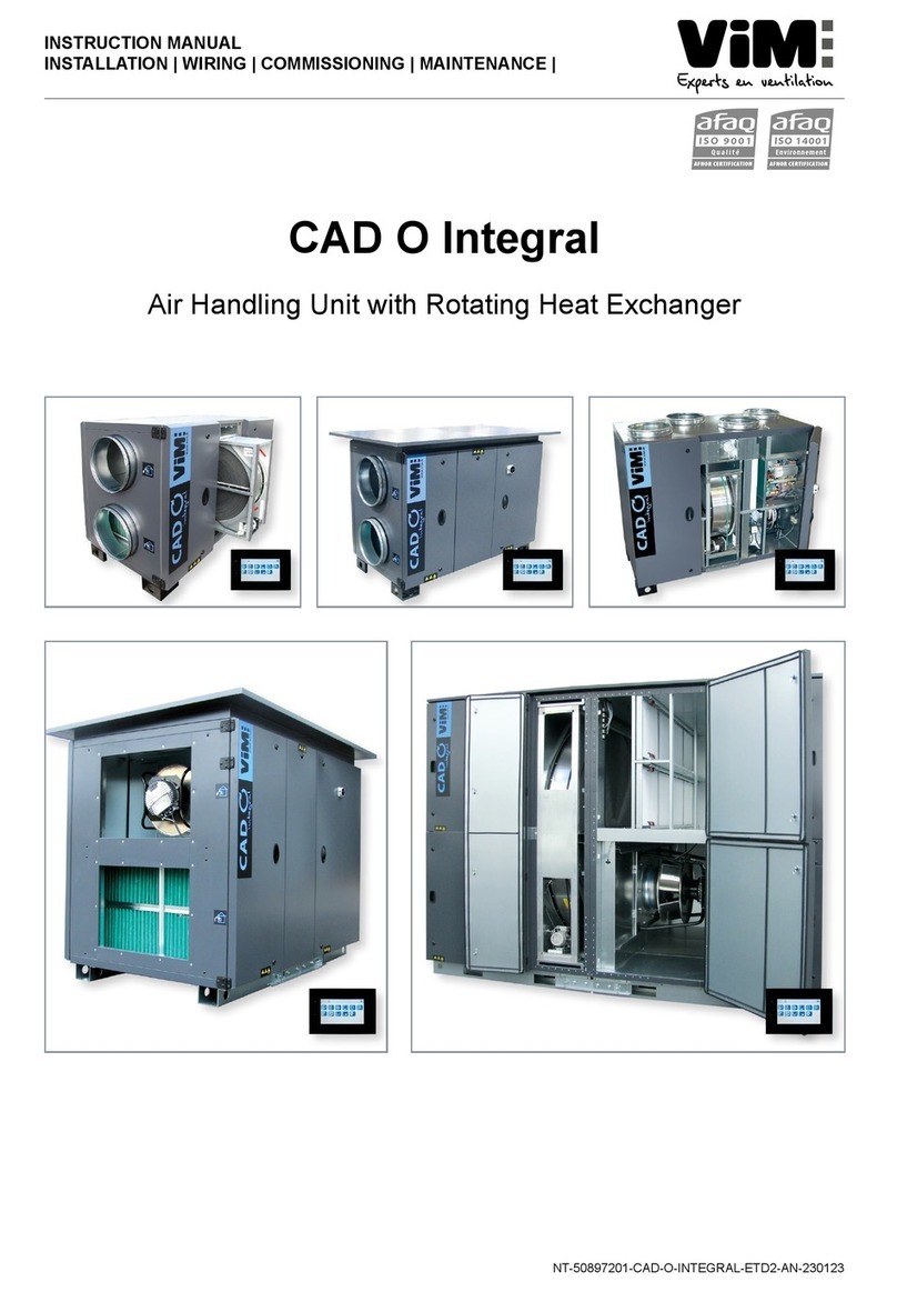
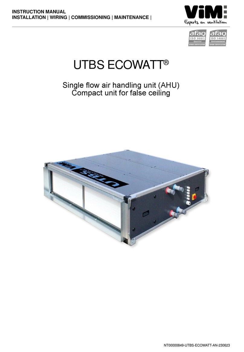
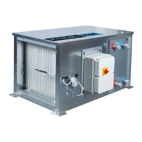
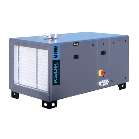
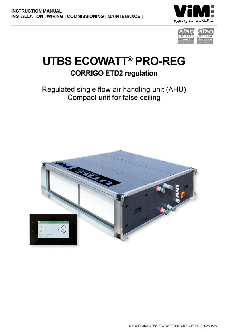
ViM KSDR ECOWATT 48 User manual

NT-50906901-KSDR-ECOWATT-48-88-120-AN-170907
INSTRUCTION MANUAL
INSTALLATION | WIRING | COMMISSIONING | MAINTENANCE |
AFNOR CERTIFICATION
ISO 14001
Environnement
AFNOR CERTIFICATION
ISO 9001
Qualité
KSDR ECOWATT® 48 / 88 / 120
Compact single fl ow air handling unit with control

NT-50906901-KSDR-ECOWATT-48-88-120-AN-170907 2/68
ENGLISH
SOMMAIRE
1. GENERAL POINTS ............................................................................................................................ 3
1.1 Warnings .................................................................................................................................. 3
1.2 Safety guidelines ...................................................................................................................... 4
1.3 Receipt - Storage...................................................................................................................... 4
1.4 Warranty ................................................................................................................................... 4
2. PRESENTATION OF RANGE - PRODUCT ....................................................................................... 5
2.1 Range ....................................................................................................................................... 5
2.2 Products - Main components .................................................................................................... 5
3. INSTALLATION .................................................................................................................................. 7
3.1 Identifi cation of unit/Symbols .................................................................................................... 7
3.2 Dimensions and weights........................................................................................................... 7
3.3 Handling ................................................................................................................................... 8
3.4 Location and Attachment .......................................................................................................... 8
4. HYDRAULIC CONNECTION ............................................................................................................ 8
4.1 Wiring of water coils ................................................................................................................. 8
4.2 Connection of valves and antifrost sensor................................................................................ 9
4.3 Connection direct expansion coils .......................................................................................... 10
5. AIRFLOW CONNECTION ................................................................................................................ 10
5.1 Connection of ducts ................................................................................................................ 10
5.2 Connection of accessories ..................................................................................................... 10
6. ELECTRICAL CONNECTION .......................................................................................................... 12
6.1 Electrical characteristics ......................................................................................................... 12
6.2 Electric panel - power supply principle ...................................................................................13
6.3 Technical characteristics of the CORRIGO controller............................................................. 14
6.4 Connection of the control with ETD display ............................................................................ 15
6.5 Input - output tables (terminal block/signal/variable/function)................................................. 16
6.6 Controller display panels ........................................................................................................ 20
6.7 Wiring diagrams of external elements, CAV, VAV and COP adjustments............................... 22
7. COMMISSIONING ............................................................................................................................ 28
8. ADJUSTMENT - FUNCTIONS/PARAMETERS ............................................................................... 29
8.1 Simplifi ed menus/Access........................................................................................................ 30
8.2 Constant fl ow operation (CAV) ............................................................................................... 33
8.3 Variable fl ow operation (VAV) ................................................................................................. 34
8.4 Constant pressure operation (COP) ....................................................................................... 35
8.5 Temperature adjustment ......................................................................................................... 36
8.6 Menu expert – contrôle des entrées/sorties du régulateur ..................................................... 38
8.7 Time programming ................................................................................................................. 39
8.8 Override .................................................................................................................................. 41
8.9 Night-time Free Cooling.......................................................................................................... 41
8.10 Anti-freeze protection of the hot water coil .............................................................................43
8.11 Entry for an external fi re signal ............................................................................................... 43
8.12 Measuring air fl ows - modifying the coeffi cient K ................................................................. 44
8.13 List of faults ............................................................................................................................ 44
9. COMMUNICATION ........................................................................................................................... 45
9.1 Connection to a Centralised Building Management in Modbus RTU language ..................... 45
9.2 Connection to a Centralised Building Management in BACnet IP language .......................... 45
9.3 Integrated web server application........................................................................................... 54
9.4 Rebooting the CORRIGO controller ....................................................................................... 62
NT-50906901-KSDR-ECOWATT-48-88-120-AN-170907 3/68
ENGLISH
10. MAINTENANCE................................................................................................................................ 64
10.1 Prior precautions .................................................................................................................... 64
10.2 Maintenance frequency .......................................................................................................... 64
10.3 Maintenance/replacement of the fresh air fi lter ..................................................................... 64
10.4 Casing maintenance ............................................................................................................... 65
10.5 Maintenance/replacement of the fan ...................................................................................... 65
10.6 Maintenance/replacement of the electric heater..................................................................... 65
10.7 Replacement parts ................................................................................................................. 66
10.8 Maintenance/replacement of the water coil ............................................................................ 66
10.9 Replacement of the CORRIGO controller battery .................................................................. 67
11. WASTE MANAGEMENT .................................................................................................................. 67
11.1 Treatment of Packaging and non-hazardous waste ............................................................... 67
11.2 Treatment of professional WEEE ...........................................................................................67
1. GENERAL POINTS
1.1 Warnings
This product has been manufactured in compliance with a number of technical safety rules and regula-
tions, according to EC standards. The EC declaration, along with the instructions, can be downloaded from
the website www.vim.fr.
Before installing and using this product, please read these instructions carefully as they contain signifi cant
guidelines for your safety and the safety of users during the installation, commissioning and maintenance
of this product.
Once you have installed the product, attach these instructions to the machine so that they are available for
subsequent consultation.
This product must be installed (implementation, wiring, commissioning, maintenance) and all other in-
terventions must be performed by a professional in application of any applicable safety trade standards,
regulations and rules.
The installation must conform to the requirements in relation to Electromagnetic Compatibility and the Low
Voltage Directive.
VIM may not be held responsible for any bodily injury and/or damage to property caused in the event that
the safety guidelines are not respected or if the product is in any way modifi ed.
The KSDR ECOWATT® single fl ow units are intended for single air fl ow ventilation and air handling appli-
cations in kitchens or tertiary buildings.
Indoor (recommended) or outdoor installation:
• Max. permanent environment temperature:
--25°C/+60°C for size 48.
--25°C/+50°C for size 88.
--25°C/+40°C for size 120.
• To prevent any damage to electronic components (very low temperature, condensation), the safety
switch located on the front panel must be kept in the "ON" position with the exception of any main-
tenance periods.
• Relative humidity: max. of 95% without condensation.
• Potential explosive atmosphere: N/A
• Atmosphere with low salinity, without any corrosive chemical agents.

NT-50906901-KSDR-ECOWATT-48-88-120-AN-170907 4/68
ENGLISH
1.2 Safety guidelines
• Make sure that you use the appropriate PPE (Personal Protective Equipment) before any handling
operation.
• Before installing the air handling unit, make sure that the support and location are resistant enough
to bear the weight of the unit and accessories.
• Observe with the danger labels present on the various access doors or panels:
• Electrical equipment/Rotating machine/Potentially fl ammable dust-laden fi lters:
FIRE DANGER
DIRTY FILTERS ARE
INFLAMMABLE
• Do not open the access doors until the electrical power has been cut from the padlockable switch
disconnecter located on the unit.
• If there is work to be performed on the device, cut the electrical power on the main circuit breaker
and make sure that nobody is able to accidentally restart it.
• Make sure that any mobile parts are stationary.
• Check that the plug fan is not accessible from the wiring spur line (wiring duct or steel mesh protec-
tion).
Before starting-up the device, check the following points:
• Make sure that the device does not contain any foreign bodies.
• Check that all the components are fastened in their original locations.
• Manually check that the fan does not scrape and is unblocked.
• Check the wiring of the earthing electrode.
• Check that the access lid is securely closed.
1.3 Receipt - Storage
In the event of any fault, non-conformity or total or partial breakdown of the delivered products, the Buyer
must issue its written reservations on the carrier's receipt in accordance with Article 133-3 of the French
Commercial Code and confi rm them within 72 hours by registered letter with a copy sent to VIM.
If the Buyer does not issue any reservations upon receipt, it may not take any subsequent action against
us.
The product must be kept out of bad weather and protected from any impacts and stains caused by any
projections of any kind during its transport from the supplier to the end client, and on the work site prior to
installation.
1.4 Warranty
The equipment supplied by VIM is under a 12-month warranty - Parts only - as of the invoice date. VIM
undertakes to replace any parts or equipment which are recognised as being faulty by our services, with
the exception of any damages or penalties such as operating losses, commercial damage or other moral
prejudice or indirect damages.
Our warranty excludes any faults related to any improper use or any use that is not in keeping with the
recommendations of our instructions, any fl aws observed following normal wear and tear, any incidents
caused by negligence, a lack of monitoring or maintenance or any faults due to a poor installation of the
devices or unsuitable storage conditions prior to assembly.
Under no circumstances may VIM be held responsible for any transformed or even any partially repaired
equipment.

NT-50906901-KSDR-ECOWATT-48-88-120-AN-170907 5/68
ENGLISH
2. PRESENTATION OF RANGE - PRODUCT
2.1 Range
Use: Supply of fresh air into buildings with heating or cooling. Installation on stands or attached by
brackets, either indoors or outdoors.
3 sizes : 48 (4 800 m3/h), 88 (8 800 m3/h), 120 (14 000 m3/h).
8 Models :
• KSDR ECOWATT®
-EI: electric heater integrated.
-EC: heating water coil integrated.
-EF: cooling water coil integrated.
-ER: reversible heating/cooling water coil integrated.
-ECF: heating and cooling water coils integrated.
-EX: direct expansion coils.
-EG: run around coil integrated.
-EGC: run around coil and heating coil integrated.
2 Confi gurations:
• EXD: External arrangement, right hand access and connection sides, in air direction.
• EXG: External arrangement, left hand access and connection sides, in air direction.
Communicating controller assembled/wired ready to be connected:
Variable fl ow (VAV), constant fl ow (CAV), constant pressure (COP).
Temperature adjustment by integrated CORRIGO controller specifi c to VIM.
Modbus communicating on RS485 port and Bacnet IP on TCP/IP port.
ETD remote touch control included.
Example of complete designation: KSDR ECOWATT® EI 48 EXD CORRIGO Bat Elec Tri 45kW CTA
2.2 Products - Main components
Coil/heater arrangements: electrical (EI), hot water (EC), cold (EF), reversible (ER) or hot and cold water (ECF):
EI Model Marking Designation
8
9
10
11
1
2
3
5
4
6
7
1
2
3
4
5
6
7
8
9
10
11
Pre fi lter
Filter
Plug fan
Filter clogging pressure switch
Control board
Electrical heater
Safety thermostats
Outdoor air temperature sensor
Supply air temperature sensor
Roof insulation
Bottom insulation

NT-50906901-KSDR-ECOWATT-48-88-120-AN-170907 6/68
ENGLISH
Models EC, EF et ER Marking Designation
3
5
8
9
6
7
10
11
1
2
4
12
1
2
3
4
5
6
7
8
9
10
11
12
Pre fi lter
Filter
Plug fan
Filter clogging pressure switch
Control board
Reversible water coil
Droplet eliminator
Outdoor air temperature sensor
Supply air temperature sensor
Roof insulation
Bottom insulation
Drain tray
Model ECF Marking Designation
1
2
3
5
4
6
10
11
7
9
12
13
8
1
2
3
4
5
6
7
8
9
10
11
12
13
Pre fi lter
Filter
Plug fan
Filter clogging pressure switch
Control board
Heating water coil
Cooling water coil
Drain tray
Droplet eliminator
Outdoor air temperature sensor
Supply air temperature sensor
Roof insulation
Bottom insulation
Size 120 includes a steel damper between fi lters and coil(s), for antifrost protection and ERP CH38 French
regulation compliant.

NT-50906901-KSDR-ECOWATT-48-88-120-AN-170907 7/68
ENGLISH
3. INSTALLATION
3.1 Identifi cation of unit/Symbols
Identifi cation label - glued to the machine above the control unit
Label
characteristics
16278
KSDR ECOWATT ECF48 D
CODE : 685347
Made in France
U = 3~ 400V - 50/60 Hz
I Nom / RC = 2.3 A
P = 1.5kW
Q Nom = 4800m
3
/h
:258kg
www.vim.fr
CORRIGO Bat Eau chaude+froide CTA
General data
Motor data
U = 3~ 400V - 50/60 Hz I Nom / RC = 1,7 A 2140 RPM
Filter data
M5 DP initial / final = 60/200 Pa
F7 DP initial / final = 65/200 Pa
Bat/Coil data
ECF Eau chaude/Hot water + Eau froide/Cold water
3.2 Dimensions and weights
Indoor model Outdoor model
E
A
F
J
C
K
D
I
M8(*)
GB
H
L
J
K
N
M
Size A B C D E
KSDR ECOWATT
®
48 1715 1000 800 620 925
KSDR ECOWATT
®
88 1950 1315 1100 810 1165
KSDR ECOWATT
®
120 2400 1315 1100 1100 1465
Size F
G
(except
EI)
G
(EI) HI
KSDR ECOWATT
®
48 100 100 65 840 650
KSDR ECOWATT
®
88 100 100 65 1140 850
KSDR ECOWATT
®
120 100 100 65 1140 1188
*6 écrous sertis en tailles 88 et 120.
Weight (kg) EI EC/EF/ER ECF EG EX
KSDR ECOWATT
®
48 278 233 258 255 237
KSDR ECOWATT
®
88 417 350 387 383 356
KSDR ECOWATT
®
120 696 586 646 638 593
Size J K L M N
KSDR ECOWATT
®
48 1975 1175 1020 90 90
KSDR ECOWATT
®
88 2210 1485 1270 150 150
KSDR ECOWATT
®
120 2400 1485 1470 150 150

NT-50906901-KSDR-ECOWATT-48-88-120-AN-170907 8/68
ENGLISH
3.3 Handling
The units are delivered already screwed to pallets
made to fi t the sizes of the casing.
KSDR ECOWATT® air handling units can be han-
dled by pallet truck, by forklift truck or by crane.
Handling machines will be adapted to the raising
load and conditions.
The lifting will be preformed in all cases from the
base of the device attached to a pallet. The centre
of gravity is located at the centre of the unit.
The device must be handled with care and only in a
horizontal position.
3.4 Location and Attachment
The KSDR ECOWATT® AHU must be placed on a horizontal and smooth surface that is able to bear the
load. The EXD and EXG models are intended for indoor or outdoor installation.
In all cases, provide for any ducts, wiring accessories, anti-vibration and anti-freezing protection equipment
of the water coil. In areas with a high snowfall, additional protection should be considered. It is important to
provide for enough space so that the panels can be opened, started p and maintained (fi lter, fan, coils/electric
heaters). No not place the unit against a wall in order to prevent the transmission of structure-borne noise.
The casing must be attached to a completely fl at support by the side holes provided for this purpose. As-
sembly operations should be performed on anti-vibration supports or plates and the wiring should involve
soft spool pieces.
Provide the following necessary clearances for maintenance operations:
4. HYDRAULIC CONNECTION
4.1 Wiring of water coils
The hydraulic features of the unit are particular to your installation and
are determined by IT selection: Loss of head in relation to the water/Flow
of water. Refer to the selection in order to dimension the network, acces-
sories and pump.
The connection of the piping to the coil must not impose any mechanical,
vibration or thermal (dilatation) constraints.
Coils are delivered already threaded at the ends.
During tightening on the threading of the coil, keep the piping in reverse,
for instance using a pin spanner to stop the pipes from becoming dam-
aged through twisting.
Respect the water input and output direction indicated on the label glued
to the coil panel.
Sizes / Arrangements Coil header diameters
48 88 120
EC 1" 1"1/4 2"
EF 1" 1"1/2 2"
ER 1" 2" 2"
EG 3/4" 1" 2"

NT-50906901-KSDR-ECOWATT-48-88-120-AN-170907 9/68
ENGLISH
Discharge of drain tray (ER, EF and ECF versions only)
H
H
2H
The installed coil is equipped with an eliminator and
a stainless steel drain tray welded at the angles.
The drain tray outlet is 35mm long and has a 14mm
diameter. A siphon is required to guarantee the pro-
per water removal. H measurement must always
be equivalent at twice the casing negative pressure
(mm water column).
Change over thermostat (ER versions only)
A Change over thermostat (THCO sensor) should be installed on the hydraulic network and wired to the
electric panel of the unit. It allows the control of the mixing valve to be inverted in installations with only one
coil, according to the fl uid temperature detected at the entry to the valve.
B
C
ABLACK (cold)
BROWN (hot)
RED (hot)
Technical features:
• Inverter Contact Output 240 V~, 3 A
• Calibration of C-A Contact open 30 ± 4 °C
• C-A Contact closed 15 ± 4 °C
• Spring locking on the piping
• Electrical wiring of 3 wires of 1,500 mm
• IP 65 protection
towards coil
water inlet change-over
thermostat
4.2 Connection of valves and antifrost sensor
Change-over coil with THCO sensor and antifrost sensor
antifrost sensor
The coil tubes are 1", no gas, with a male thread at the end.
Motorised 3-way valves are not delivered already assembled.
Respect the positioning of the mixing valve on the network and the water input and output directions indi-
cated on the label glued to the coil panel.
Check the proper state and wiring of the antifrost sensor set on hot water outlet (heating coil or reversible
coil).

NT-50906901-KSDR-ECOWATT-48-88-120-AN-170907 10/68
ENGLISH
4.3 Connection direct expansion coils
Refrigeration connections must be done in the state of art by a qualifi ed refrigeration engineer.
5. AIRFLOW CONNECTION
5.1 Connection of ducts
Ducts should not exercise any mechanical constraints on the unit.
Check that the plug fan is not accessible from the connection spur line (protection by the connection duct
or steel mesh air inlet).
Do not reduce the diameter of ducts at the exit of connection spur lines.
On the other hand, the diameter can be increased to reduce the passage speeds in the network and to limit
the head losses, energy consumption and noise level.
According to the confi guration of the installation and the required noise level, the addition of a silencer may
be necessary at the air supply.
Take care in sealing the networks over all their lengths, from the inputs to the outputs.
The fresh air duct must be insulated at all times to prevent any leakage and condensation problems. The
insulation level, especially in cold rooms and regions, must be reinforced.
Applicable regulations must be respected in all cases as a minimum requirement.
5.2 Connection of accessories
For all electrical connections on the cabinet of the KSDR ECOWATT® : please see §"6.7 Wiring diagrams
of external elements, CAV, VAV and COP adjustments.", page 22.
Motorised damper
When the unit is fi tted with a water coil, you should consider the use of a motorised damper with anti-freeze
protection located on the fresh air network. Whenever possible, use a motorised damper with reinforced
sealing.
Use Code Designation Description
KSDR ECOWATT
®
48 170286 CDR 100 F 800 x 610 Antifrost or fi re damper
KSDR ECOWATT
®
88 170349 CDR 100 F 1100 x 910 Antifrost or fi re damper
KSDR ECOWATT
®
120 Fitted damper, available on EI arrangement.
Extract air sensor
For room temperature adjustment, you must install an air temperature sensor in the desired room. For
return temperature adjustment, a duct temperature sensor must be assembled for recirculation.
Code Designation Description
132258 TG-R5/PT1000 Room temperature sensor
132257 TG-K3/PT1000 Duct temperature sensor
Control units
1 or 2 speed comfort control units, high speed activation panel.
Code Designation Description
720420 BDEA Shunt release panel
730395 BCCA 1V 1 speed comfort control unit
730400 BCCA 2V 2 speed comfort control unit
Sizes 48 88 120
(liq/gas) coil header diam. 22/35 mm 28/35 mm 28/42 mm
Coil volume 5 l. 7 l. 10 l.

NT-50906901-KSDR-ECOWATT-48-88-120-AN-170907 11/68
ENGLISH
Diff erential pressure sensor – Operating in COP (Constant Pressure)
For constant pressure operations, you must install a pressure sensor in the supply duct at a minimum dis-
tance of 2 times the diameter of the connection.
Application Code Designation Description
KSDR ECOWATT
®
08/38 132105 SPRD-B 800 Pressure sensor in panel 0-800 Pa 0,5-4,5V
SPRD accessory 132143 KTPR 2 pressure sensor kit + screws + 2 m translucent tube
Air quality sensor to measure CO2 - Operating in VAV (Variable fl ow)
For variable fl ow operations, you must install an air quality (generally CO2) sensor either in return air duct,
or room air duct in the room to be treated.
Code Designation Description
132376 SCO2 AA-010-400-1100 Room sensor with 400-1000 ppm display 0-10V Output signal
132262 SHUR-010 SHUR 0-10 Hygrometry sensor 0-100% RH wall assembly
132375 SCO2 A-010-400-1100 Room sensor without 400-1000 ppm display 0-10V Output signal
132377 SCO23 G MIX 400-1100 400-1100 ppm Duct sensor 0-10V or 4-20mA Output signal
Pressure switch setting for the second fi lter stage
• Unplug the pipe connected to the second fi lter way out connection and plug it to the way out connec-
tion of the fi rst fi lter.
• Set the second pressure switch below the fi rst one already set, into the motor box.
• Plug both pipes of the second pressure switch to the second fi lter way in and way out connections.
• Plug the electrical connections of this second pressure switch to points 23 and 24 of the Corrigo
controller.
Setting point of those 2 pressure switch must be adjusted like this:
SECOND PRESSURE SWITCH SETTING
DP1
ou
DP2
Câble 5G1
tube
"rilsan"
pour faciliter
le repérage
n° des bornes =
n° des ls
24V
A04
23
24
7
8
5
6
3
4
1
2
25
26
27
28
A03
A02
A01
10
9
+24V
12
11
+24V
14
13
+24V
21
22
24V
24V
24V
on G0
Gnd
Gnd
Gnd
Gnd
41
42
35
36
33
34
31
32
61
62
63
64
24V
A04 Gnd
24V
D
V+
G0
16
15
+24V
24V
A05 Gnd
37
38
B2
B1 B3
"rilsan" pipe
To ease
marking
point
n° = is n°
5G1 wire
or
Pressure switch setting values Code Designation Description
Sizes DP1 DP2
48 150 Pa 250 Pa 720430 BDEZ 100-1000 Pressure switch 100-1000Pa IP54
88 150 Pa 250 Pa
120 200 Pa 250 Pa

NT-50906901-KSDR-ECOWATT-48-88-120-AN-170907 12/68
ENGLISH
6. ELECTRICAL CONNECTION
6.1 Electrical characteristics
The power or connection cables of accessories must pass through the grommets provided on the adjust-
ment cabinet on the front panel.
Overall unit
Power and intensity for the whole KSDR ECOWATT® selected.
Capacity of the power connection terminal block: 10 mm2, coupling torque: 2.5Nm
Modèle Fan
Max speed (tr/min.) Freq. (Hz) Voltage (V) Abs. P. (W) Current (A)
KSDR ECOWATT
®
48 EI 2 140 50/60 3 Ph. 400V 1 000 1,7
KSDR ECOWATT
®
48 EI 2 140 50/60 3 Ph. 400V 1 000 1,7
KSDR ECOWATT
®
48 EI 2 140 50/60 3 Ph. 400V 1 000 1,7
KSDR ECOWATT
®
48 EC-EF-ER-ECF-EX-
EG-EGC 2 140 50/60 3 Ph. 400V 1 000 1,7
KSDR ECOWATT
®
88 EI 2 040 50/60 3 Ph. 400V 2 730 4,2
KSDR ECOWATT
®
88 EI 2 040 50/60 3 Ph. 400V 2 730 4,2
KSDR ECOWATT
®
88 EI 2 040 50/60 3 Ph. 400V 2 730 4,2
KSDR ECOWATT
®
88 EC-EF-ER-ECF-EX-
EG-EGC 2 040 50/60 3 Ph. 400V 2 730 4,2
KSDR ECOWATT
®
120 EI 1 500 50/60 3 Ph. 400V 5 700 9
KSDR ECOWATT
®
120 EI 1 500 50/60 3 Ph. 400V 5 700 9
KSDR ECOWATT
®
120 EI 1 500 50/60 3 Ph. 400V 5 700 9
KSDR ECOWATT
®
120 EC-EF-ER-ECF-EX-
EG-EGC 1 500 50/60 3 Ph. 400V 5 700 9
Modèle
Electrical heater Unit
Voltage
(V)
Abs.
P.
(kW)
Pin number
and abs. P.
Current
(A)
Voltage
(V)
Abs.
P.
(kW)
Current
(A)
KSDR ECOWATT
®
48 EI 3 Ph. 400V 45 15x3kW 65 3 Ph. 400V 48 70
KSDR ECOWATT
®
48 EI 3 Ph. 400V 9 3x3kW 13 3 Ph. 400V 11 15
KSDR ECOWATT
®
48 EI 3 Ph. 400V 27 9x3kW 39 3 Ph. 400V 30 43
KSDR ECOWATT
®
48 EC-EF-ER-ECF-EX-
EG-EGC - - - - 3 Ph. 400V 1,2 2
KSDR ECOWATT
®
88 EI 3 Ph. 400V 90 18x5kW 129,9 3 Ph. 400V 97 141
KSDR ECOWATT
®
88 EI 3 Ph. 400V 30 6x5kW 43,3 3 Ph. 400V 34 50
KSDR ECOWATT
®
88 EI 3 Ph. 400V 60 12x5kW 86,6 3 Ph. 400V 66 95
KSDR ECOWATT
®
88 EC-EF-ER-ECF-EX-
EG-EGC - - - - 3 Ph. 400V 3 4,5
KSDR ECOWATT
®
120 EI 3 Ph. 400V 105 21x5kW 151,6 3 Ph. 400V 116 169
KSDR ECOWATT
®
120 EI 3 Ph. 400V 45 9x5kW 65 3 Ph. 400V 53 78
KSDR ECOWATT
®
120 EI 3 Ph. 400V 75 15x5kW 108,3 3 Ph. 400V 85 123
KSDR ECOWATT
®
120 EC-EF-ER-ECF-EX-
EG-EGC - - - - 3 Ph. 400V 6 9
El model - Technical data of electric heaters
An electric heater is installed inside the unit of the EI models. It is fully wired and connected to the controller.
Location of thermostats and reinforcement of the manual thermostat:
Overheat control
Thermostat
with automatic
resetting
Thermostat
with manual
resetting

NT-50906901-KSDR-ECOWATT-48-88-120-AN-170907 13/68
ENGLISH
Units equiped with electric heaters can have lower heating powers upon request bold powers available in
our catalogue.
Sizes Power
supply
Step
number
Resistance
no.
Power of a
pin
(kW)
Total
(kW) Possibility of reducing power
KSDR ECOWATT
®
48 400V - 3 Ph 3 15 3 45
9 KW by removing 12 resistances
18 KW by removing 9 resistances
27 KW by removing 6 resistances
36 KW by removing 3 resistances
KSDR ECOWATT
®
88 400V - 3 Ph 3 18 5 90
15 KW by removing 15 resistances
30 KW by removing 12 resistances
45 KW by removing 9 resistances
60 KW by removing 6 resistances
75 KW by removing 3 resistances
KSDR ECOWATT
®
120 400V - 3 Ph 3 21 5 105
15 KW by removing 18 resistances
30 KW by removing 15 resistances
45 KW by removing 12 resistances
60 KW by removing 9 resistances
75 KW by removing 6 resistances
90 KW by removing 3 resistances
6.2 Electric panel - power supply principle
KSDR ECOWATT® with water coil
M
M
M
Power supply of the servo-motor
coming from unit control cabinet
Servo-motor
(accessory)
Fresh air damper
(accessory)
Control
cabinet
Servo-motor
heating coil
Servo-motor
cooling coil
Direction of
air fl ow
Direction of
air fl ow
General power
supply
(client)

NT-50906901-KSDR-ECOWATT-48-88-120-AN-170907 14/68
ENGLISH
KSDR ECOWATT® with electrical battery
M
Power supply of the servo-motor
coming from unit control cabinet
Servo-motor
(accessory)
Fresh air damper
(accessory)
Electrical
battery
Control
cabinet
Direction of
air fl ow
Direction of
air fl ow
General power supply
(client)
To access to electrical commands the panel below the cable gland panel needs to be dismantled.
A panel equipped with cable glands is dedicated for power and command wire connections.
6.3 Technical characteristics of the CORRIGO controller
• Power voltage 24 V AC ±15%, 50.60Hz or 21.36 V DC
• Power consumed of E.W-3 models: 12 VA, 6 W (DC)
• Room temperature 0...50°C
• Storage temperature -40...+50°C
• Max. room humidity 90% RH
• Protection index IP20
• Connection of withdrawable terminal blocks, 4 mm2
• Saving the memory: an integrated long-life battery allows adjustments to be saved over an extended
period, with real time included.
Electromagnetic compatibility directive:
This product meets the requirements of directive 2004/108/EC of the European Parliament and Council
(EMC) through compliance with standards EN 61000-6-1 and EN 61000-6-3.
RoHS:
This product meets the requirements of directive 2011/65/EU of the European Parliament and Council.
Input
Analogue input for PT1000 sensors (precision +I- 0,4°C) or 0...10 V DC (precision +I- 0,15% of the whole
output signal). 12-bit resolution in the A/D signal conversion.
Digital input for potential-free contacts
Output
Analogue output 0...10 V DC, 1 mA, protection against short-circuits Digital output Mosfet output, 24 V AC/
DC, continuous 2 A. Max. 8 A in total.
Communication ports
1 Web server TCP/IP port, TCP/IP communication, BACnet/IP.
2 Modbus and EXOline Communication RS485 ports (REGIN language).

NT-50906901-KSDR-ECOWATT-48-88-120-AN-170907 15/68
ENGLISH
Indications
Operation indications: the green LED is lit when the CORRIGO is powered up.
Alarm indication: the red LED fl ashes and the alarm text is displayed on screen.
General alarm: this output can be confi gured
E tool© confi guration software
Required equipment: operating system of MS Windows 2000, 8, 7, XP, Vista, Windows 7, Windows 8 or
Windows 10 available on www.vim.fr.
6.4 Connection of the control with ETD display
The ETD touch screen is delivered with a 10 m cable (possible extension up to 100m) fi tted with a RJ10 4PC4
connector for wiring to the CORRIGO. For a use over 10 m, use a shielded cable connected to the ground.
Do not set the ETD wire nearby a power cable. Use the available grommet to connect to the inside of the unit.
The ETD control is IP30; it is exclusively reserved for use indoors and protected from any humidity.
It is fi tted with an internal temperature sensor.
Once it has been confi gured, the command control can be disconnected.
Wiring diagram
21.4°C
201 2 - 0 6 -26 14: 02
2500 m3/h
Run mode: On
Alarm : n°1 Ventilate +C
Gnd
A
B
ETD remote control
Connection inside the single air ow unit
Port N°2Port N °1
(ModBus
network)
Port 3
BLACK
YELLOW
WHITE
BROWN
Cable (code 132389)
TCP/IP
OEM-Controller
45 UI4
44 UI3
43 Agnd
42 UI2
41 UI1
40 Agnd
35 AI4
34 AI3
33 Agnd
32 AI2
31 UI1
30 Agnd
17 DO7
16 DO6
15 DO5
14 DO4
13 DO3
12 DO2
11 DO1
10 GDO
4+C
2GO-
1G+
AO5 95
AO4 94
AO3 93
AO2 92
AO1 91
Agnd 90
DI8 78
DI7 77
DI6 76
DI5 75
DI4 74
DI3 73
DI2 72
E63
Ext.
Disp.
N62
A61
B60
E53
P
1
A51
B50
P
2
P1 RxTx
P2 RxTx
TCP/IP
P/B
(ModBus
network)
(TCP/IP
network)
Implementation of the support and command control
Fastening support ETD command control
94.3
71.4
27
14
7.4
3.5
7.4
3.5
17
17
17
35 .735.7
69
51
91
120
233

NT-50906901-KSDR-ECOWATT-48-88-120-AN-170907 16/68
ENGLISH
6.5 Input - output tables (terminal block/signal/variable/function)
KSDR ECOWATT® 48 - EI model
DI3
DI4
DI2
DI1
Agnd
AO1
AO3
AO2
GG0
+C
DO4
DO3
DO1
DO2
G0
Agnd
Agnd
Agnd
DO5
DO7
DO6
DI7
DI8
DI6
DI5
AO5
AO4
Ext. Disp
N 62
B 60
E 53
P2
E 63
A61
N52
A51
B 50
P1
KM1
KM2
KM3
KM4
KM5
KM6
KM7
TCP/IP
AI2
AI1
AI4
AI3
UI2
UI1
Agnd
UI4
UI3
35
246
1
CORRIGO
Fan pressure
sensor
Identy plate
Transformer
400Vac/24Vac
Supply ON
HS ON
Fresh air
damper ON
Alarms
3rd step heater ON
2nd step heater ON
Defrosting
Customer main
power supply
Motorfan
power supply
Heater resistance
AC power supply
23
7
53
125 27
21 41353331 61 6337
24
86
42 26 28
22 42
363432 62 6438
S1 Supply T° sensor
S3 Extract T° sensor
S4 External T° sensor
Pr10 Antifreeze sensor
Pr1+Pr2 Safety therm./DX defrosting alarm
Fire/Kitchen smoke extract
External HS/LS command
External ON/OFF
Change-over thermostat
DP2 (Filter 2)
DP
DP1 (Filter 1)
θ
X°C
-
DP
Y1 -PWM
DX group defrosting
Heater state
+24V+24V+24V G0 Gnd Gnd Gnd Gnd Gnd
G0 B3
+24V Gnd
24V
A04A03A02A0110
9
12
11
14
13 24V 24V 24V
ON
24V
A04
24V
D
V+ B2
B116
15 24V
A05
External command (0-10, COP,...)
External command (CO2)
Y1 signal (heating)
Y2 signal (extra loop)
Y3 signal (cooling)
Antifrost damper
Supply
Pressure sensor (inlet)
External command (CVF)
Pressure sensor (outlet)
M1
Supply
-
Pr1+Pr2 feed-back &
KMba/bb/bc command
PE
PE
L1 L2 L3

NT-50906901-KSDR-ECOWATT-48-88-120-AN-170907 17/68
ENGLISH
KSDR ECOWATT® 88 / 120 - EI model
248642262822 42363432 62 6438
θ
X°C
+24V+24V+24V G0 Gnd Gnd Gnd Gnd GndG0 B3
+24V Gnd
24V
A04A03A02A0110
9
12
11
14
13 24V 24V 24V
ON
24V
A04
24V
D
V+ B2
B116
15 24V
A05
Motorfan
power supply
PE
Customer main
power supply
ML5-200-3V
ON
OFF Heater resistance AC
power supply
DI3
DI4
DI2
DI1
Agnd
AO1
AO3
AO2
GG0
+C
DO4
DO3
DO1
DO2
G0
Agnd
Agnd
Agnd
DO5
DO7
DO6
DI7
DI8
DI6
DI5
AO5
AO4
Ext. Disp
N 62
B60
E 53
P2
E 63
A 61
N 52
A 51
B 50
P1
KM1
KM2
KM3
KM4
KM5
KM6
KM7
TCP/IP
AI2
AI1
AI4
AI3
UI2
UI1
Agnd
UI4
UI3
CORRIGO
Fan pressure sensor
Identy plate
Transformer
400Vac/24Vac
Supply ON
HS ON
Fresh air damper ON
Alarms
3rd step heater ON
2nd step heater ON
Defrosting
23
7
53
125 27
21 41353331 61 6337
DP
-
DP
M1
-
S1 Supply T° sensor
S3 Extract T° sensor
S4 External T° sensor
Pr10 Antifreeze sensor
Pr1+Pr2 Safety therm./DX defrosting alarm
Fire/Kitchen smoke extract
External HS/LS command
External ON/OFF
Change-over thermostat
DP2 (Filter 2)
DP1 (Filter 1)
Y1 -PWM
DX groupe defrosting
Heater state
External command (0-10, COP,...)
External command (CO2)
Y1 signal (heating)
Y2 signal (extra loop)
Y3 signal (cooling)
Antifrost damper
Supply
Pressure sensor (inlet)
External command (CVF)
Pressure sensor (outlet)
Supply
Pr1+Pr2 feed-back &
KMba/bb/bc command

NT-50906901-KSDR-ECOWATT-48-88-120-AN-170907 18/68
ENGLISH
KSDR ECOWATT® 48 / 88 / 120 EC, ER, EF, ECF, EX models
Powerfan
motor supply
PE
L1 L2 L3
Customer main
power supply
PE
23
7
5
3
125 27
21 41
353331 61 6337
24
86
42 26 28
22 42
363432 62 6438
DP
θ
X°C
-
DP
+24V+24V +24V G0 Gnd Gnd Gnd Gnd GndG0 B3
+24V Gnd
24V
A04A03A02A0110
9
12
11
14
13 24V 24V 24V
ON
24V
A04
24V
D
V+ B2
B1
16
15 24V
A05
M1
-
Supply ON
HS ON
Fresh air damper ON
Alarms
Defrosting
CORRIGO
Fan pressure sensor
Identy plate
Transformer
400Vac/24Vac
DI3
DI4
DI2
DI1
Agnd
AO1
AO3
AO2
GG0
+C
DO4
DO3
DO1
DO2
G0
Agnd
Agnd
Agnd
DO5
DO7
DO6
DI7
DI8
DI6
DI5
AO5
AO4
Ext. Disp
N 62
B 60
E 53
P2
E 63
A 61
N 52
A 51
B 50
P1
TCP/IP
AI2
AI1
AI4
AI3
UI2
UI1
Agnd
UI4
UI3
KM1
KM2
KM3
KM4
KM7
35
246
1
S1 Supply T° sensor
S3 Extract T° sensor
S4 External T° sensor
Pr10 Antifreeze sensor
Pr1+Pr2 Safety therm./DX defrosting alarm
Fire/Kitchen smoke extract
External HS/LS command
External ON/OFF
Change-over thermostat
DP2 (Filter 2)
DP1 (Filter 1)
Y1 -PWM
DX group defrosting
Heater state
External command (0-10, COP,...)
External command (CO2)
Y1 signal (heating)
Y2 signal (extra loop)
Y3 signal (cooling)
Antifrost damper
Supply
Pressure sensor (inlet)
External command (CVF)
Pressure sensor (outlet)
Supply
Pr1+Pr2 feed-back &
KMba/bb/bc command

NT-50906901-KSDR-ECOWATT-48-88-120-AN-170907 19/68
ENGLISH
E28 N° bornes KSDR 48 - 88 - 120
Analogue inputs
AI1 (1-2) Supply temperature sensor
AI2 (3-4) Free / return sensor
AI3 (5-6) Free / Water temperature sensor with anti-freeze protection (Water coil)
AI4 (7-8) Fresh air temperature sensor
Analogue inputs (universal)
UIA1 (10-9-+24V) External fan setting point (0-10V...) / extra external pressure sensor (COP running mode)
UIA2 (12-11-+24V) Free / CO2 sensor (mixing damper control)
UIA3 (14-13-+24V) Pressure sensor (supply fan inlet cone)
UIA4 (16-15-+24V) Free
Digital input (on-off )
DI1 (21-22) Extra alarm 10 - DX group defrosting
DI2 (23-24) Filter check
DI3 S KMba(25-26) Electrical heater safety thermostats
DI4 (27-28) Change-over sensor
DI5 (31-32) External off
DI6 (33-34) External LS/HS requested
DI7 (35-36) Adjustable fi re input
DI8 (37-38) Free
Analogue outputs
AO1 (G0 - 24 - A01) Y1 (Y3) Heating signal (or dual mode)
AO2 (G0 - 24 - A02) Extra control loop signal : mixing damper = Y4 signal / Run around coil = Y2 signal
AO3 (G0 - 24 - A03) Y3 Cooling signal
AO4 (G0 - 24 - A04) Supply fan 0-10V signal and slaving
AO5 (G0 - 24 - A05) Free
Digital output (on-off )
DO1 ( KM1 ) Supply ON (Fresh air)
DO2 ( KM2 ) Supply ON (fresh air) for HS slave command
DO3 ( KM3 ) Fresh air damper (DX running signal output "D01 copy")/run around coil pump ON
DO4 KM4 (59-60) Alarms (synthesis)
DO5 KMbc 3rd Step electrical heater (sequential)
DO6 KMbb 2nd Step electrical heater (sequential)
DO7 KMba1 (41-42) 1std Step electrical heater (proportional)

NT-50906901-KSDR-ECOWATT-48-88-120-AN-170907 20/68
ENGLISH
6.6 Controller display panels
KSDR ECOWATT® with electrical heater (EI)
S1
S4
M1
DP5
Pr2Pr1
Bat1
Triac
DP1 DP3
Fl1
R
Liaison d'usine
Liaison à réaliser
par le client ETD GTC
ou
Fl2
Factory settings
To be achieved
buy the customer or
S1 Supply air temperature sensor
S4 Fresh Air temperature sensor
RCorrigo controller
PR1
&
PR2
Overheat control
M1 Motor fan
M5 Fresh air damper (accessory)
Fl1 Fresh air fi lter
DP1 Fresh air fi lter pressure switch
DP3 Airfl ow measure
DP5 Diff erential pressure sensor
(COP mode accessory)
Bat1 Electrical heater
ETD Touch display for KSDR control
KSDR ECOWATT® with cooling coil (ER / EC / EF / ECF)
M5 S1
S4
M1
DP5
R
DP3
Fl1
ETD GTC
ou
Liaison d'usine
Liaison à réaliser
par le client
Fl2
Pr10
Bat1
M6
S20
Bat2Bat1
Pr10
M6
M7
RETD GTC
ou
M5 S1
S4
M1
DP5
DP3
Fl1
DP1
Fl2
Liaison d'usine
Liaison à réaliser
par le client
DP1
Factory settings
To be achieved
buy the customer
Factory settings
To be achieved
buy the customer
or
or
S1 Supply air temperature sensor
S4 Fresh Air temperature sensor
RCorrigo controller
Pr10 Anti frost sensor
S20 Thermostat change-over
M1 Motor fan
M5 Fresh air damper (accessory)
M6 Valve with actuator
M7 Valve with actuator
Fl1 Fresh air fi lter
DP1 Fresh air fi lter pressure switch
DP3 Airfl ow measure
DP5 Diff erential pressure sensor
(COP mode accessory)
Bat1 Electrical heater
Bat2 Cooling coil
ETD Touch display for KSDR control
Other manuals for KSDR ECOWATT 48
1
This manual suits for next models
6
Table of contents
Other ViM Air Handler manuals
Popular Air Handler manuals by other brands

Trane
Trane 4TEP3F18A1000A Installer's guide

BLAUBERG Ventilatoren
BLAUBERG Ventilatoren TwinBox EC 150 user manual

Suntherm
Suntherm SEHX Series installation manual

Armstrong Air
Armstrong Air BCE7E Series installation instructions

Vents
Vents VUT EH EC Series user manual

Amana
Amana AVPEC Series Installation & operating instructions