Vimar BY-ALARM PLUS User manual

Viale Vicenza, 14
36063 Marostica VI - Italy
www.vimar.com
49401689A0 01 2212
03833.x
BY-ALARM PLUS
Contatto magnetico verticale e orizzontale per porte e finestre By-alarm Plus,
collegamento in radiofrequenza 868 MHz, 2 terminali configurabili ingresso
(anche shock) / uscita, alimentazione con 1 batteria alcalina 1.5V AA inclusa.
Il contatto magnetico radiofrequenza rileva l'apertura dell'infisso nel quale è installato; è provvisto
di due morsetti configurabili singolarmente come ingresso o uscita OC (open-collector). Quando
vengono configurati come ingressi permettono la gestione dei bilanciamenti di zona (NA, NC,
singolo bilanciamento, doppio bilanciamento) oppure possono essere utilizzati per collegare
direttamente rivelatori filari tapparella ed inerziali. Gli allarmi provenienti dal contatto magnetico e
dai singoli ingressi sono segnalati separatamente in centrale.
Il dispositivo è provvisto di un magnete che può essere fissato (tramite due viti) in due posizioni
poste a 90° l’una dall’altra; sono inoltre fornite tre basi differenti per 3 altezze di installazione
differenti (13.5, 20 e 26.5 mm), a seconda delle necessità di installazione del magnete.
Il contatto magnetico è dotato di antiapertura ed antistrappo.
COLLEGAMENTO MORSETTI CONFIGURABILI
Ai fini della conformità alle norme EN 50131, nel caso si utilizzino i morsetti "T1" o "T2" come
ingressi è necessario utilizzare il doppio bilanciamento.
BATTERIE
Il contatto magnetico è alimentato da una batteria alcalina da 1,5 V modello LR6 AA. Per proce-
dere alla sostituzione della batteria è sufficiente aprire il corpo del dispositivo e poi sostituire la
batteria facendo attenzione al corretto inserimento con le polarità indicate.
In caso di sostituzione della batteria, è opportuno premere il pulsante di ENROLL per essere certi
di sincronizzare il dispositivo con il ricevitore via radio.
ATTENZIONE! Pericolo d’esplosione in caso di batteria sostituita con altra di tipo scorretto
INSTALLAZIONE
Non installare il dispositivo su superfici ferromagnetiche o nelle vicinanze di potenziali campi
magnetici ed elettrici, in quanto questi potrebbero influire sul corretto funzionamento del dispo-
sitivo.
1. Scegliere la posizione idonea all’installazione.
2. Aprire il coperchio piegando leggermente la linguetta di ancoraggio e divaricando le due
superfici dal lato della vite di bloccaggio.
ATTENZIONE: Non rimuovere la scheda elettronica dalla sua sede.
3. Se si utilizzano i morsetti T1 e T2 collegare i cavi facendoli passare attraverso il foro passacavi
avendo cura di evitare che filamenti indesiderati dei cavi stessi entrino in contatto tra loro o
con i morsetti della batteria.
4.Mantenere la base sul punto di fissaggio e marcare i punti di fissaggio della base e dell’anti-
strappo.
VISTA FRONTALE
A: Foro del contenitore plastico
B: Foro di fissaggio
C: Foro per vite antistrappo
D: Vite di bloccaggio
E: Foro passacavi
F: Antisabotaggio
G: Morsetto GND di massa
H: Morsetto T1
I: Morsetto T2
J: Scheda elettronica
K: Batteria
L: REED contatto lato corto
M: REED contatto lato lungo
N: Led rosso di segnlazione + pulsante di configurazione ENROLL
O: Magnete lato corto
P: Magnete lato lungo
ATTENZIONE!
In caso di sostituzione, smaltire le batterie negli appositi cassonetti per la raccolta differenziata.

Viale Vicenza, 14
36063 Marostica VI - Italy
www.vimar.com
49401689A0 01 2212
5.Fissare la base e l’antistrappo con le viti di ancoraggio.
6.Se si vuole fissare il magnete con le viti fornite, rimuovere la sua base con un cacciavite.
7.Segliere la base del magnete più idonea tra le tre disponibili.
8.Posizionare la base del magnete nel lato (lungo o corto) del contatto magnetico ad una distan-
za di circa 2 mm.
N.B. Se si utilizza il lato lungo, utilizzare le tacche incise sul lato della base per allineare il
magnete e ottenere il corretto funzionamento. Se si utilizza il lato corto allineare il magnete
al contatto.
9. Fissare la base con le viti e chiudere il magnete; in alternativa fissare il magnete con l'adesivo
fornito a corredo.
10. Togliere la linguetta dalla batteria.
11. Montare il coperchio frontale sulla base del contatto ed inserire la vite di bloccaggio nell'ap-
posito foro.
12. Effettuare la configurazione mediante il software By-alarm Plus Manager aggiungendo il
dispositivo e digitando il QRCode.
CONFIGURAZIONE
Per tutti i dettagli si vedano i manuali di installazione del sistema By-Alarm Plus e del software
By-alarm Plus Manager.
REGOLE DI INSTALLAZIONE
L’installazione e la configurazione devono essere effettuate da personale qualificato con l’osser-
vanza delle disposizioni regolanti l’installazione del materiale elettrico in vigore nel paese dove i
prodotti sono installati.
Se si utilizzano rivelatori tapparella o inerziali, il cavo di collegamento non deve superare i
2 m.
CARATTERISTICHE
• Alimentazione: batteria alcalina LR6 AA 1,5 V fornita in dotazione
• Tensione di segnalazione “Batteria bassa”: < 1,15 V
• Consumo:
- 30 µA in standby
- 45 mA max in attivazione
- 50 mA max su uscita OC
• Range di frequenza: 868 MHz
• Potenza RF trasmessa: < 25 mW (14dBm)
• Tipo di comunicazione: bidirezionale
• Modulazione: GFSK
• Durata media della batteria: 4 anni
• Avviso di batteria scarica: su tastiera e in centrale
• 1 pulsante di configurazione + LED per segnalazione allarme
• Temperatura di funzionamento: da -10 a +40 °C
• Umidità relativa: ≤93% senza condensazione
• Grado di sicurezza: 2
• Classe ambientale: III
• Dimensioni (L x A x P): 26 x 108 x 26,5mm
• Peso: 50 g
CONFORMITA' NORMATIVA.
Direttiva RED. Direttiva RoHS.
Norme EN 62368-1, EN 50130-4, EN 50130-5, EN 55032, EN 50131-2-6, EN 301 489-3, EN
300 220-2, EN 62479, EN IEC 63000.
Vimar SpA dichiara che l’apparecchiatura radio è conforme alla direttiva 2014/53/UE. Il testo
completo della dichiarazione di conformità UE è disponibile nella scheda di prodotto al seguente
indirizzo Internet: www.vimar.com.
Regolamento REACh (UE) n. 1907/2006 – art.33. Il prodotto potrebbe contenere tracce di
piombo.
RAEE - Informazione agli utilizzatori
Il simbolo del cassonetto barrato riportato sull’apparecchiatura o sulla sua confezione indica che il prodotto alla fine della
propria vita utile deve essere raccolto separatamente dagli altri rifiuti. L’utente dovrà, pertanto, conferire l’apparecchiatura
giunta a fine vita agli idonei centri comunali di raccolta differenziata dei rifiuti elettrotecnici ed elettronici. In alternativa alla
gestione autonoma, è possibile consegnare gratuitamente l’apparecchiatura che si desidera smaltire al distributore, al mo-
mento dell’acquisto di una nuova apparecchiatura di tipo equivalente. Presso i distributori di prodotti elettronici con superficie
di vendita di almeno 400 m2è inoltre possibile consegnare gratuitamente, senza obbligo di acquisto, i prodotti elettronici
da smaltire con dimensioni inferiori a 25 cm. L’adeguata raccolta differenziata per l’avvio successivo dell’apparecchiatura
dismessa al riciclaggio, al trattamento e allo smaltimento ambientalmente compatibile contribuisce ad evitare possibili ef-
fetti negativi sull’ambiente e sulla salute e favorisce il reimpiego e/o riciclo dei materiali di cui è composta l’apparecchiatura.
DISTANZE DI FUNZIONAMENTO DEL MAGNETE
Nota. I valori sono stati ricavati posizionando il magnete a contatto con il dispositivo (tranne
che per l’asse y-)
Magnete da 13,5 mm
Asse Lato lungo Lato corto
Avvicinamento Allontanamento Avvicinamento Allontanamento
x± 13 14 11 13
y- 22 27 21 25
z+ 40 45 45 48
z- 21 26 23 25
Magnete da 20 mm
Asse Lato lungo Lato corto
Avvicinamento Allontanamento Avvicinamento Allontanamento
x± 11 12 13 14
y- 25 28 23 27
z+ 35 40 37 41
z- 27 31 28 32
Magnete da 26,5 mm
Asse Lato lungo Lato corto
Avvicinamento Allontanamento Avvicinamento Allontanamento
x± 9 11 14 15
y- 24 28 23 27
z± 35 40 33 37

Viale Vicenza, 14
36063 Marostica VI - Italy
www.vimar.com
49401689A0 01 2212
03833.x
BY-ALARM PLUS
By-alarm Plus vertical and horizontal magnetic contact for doors and windows,
868 MHz radio frequency connections, 2 configurable input (including shock) /
output connections, power supply with one AA 1.5V alkaline battery included.
The radio frequency magnetic contact detects when the door or window in which it is installed is
opened; it has two terminals that can be configured independently as inputs or OC (open collec-
tor) outputs. When configured as inputs, they can be used to manage zone balancing (NO, NC,
single balancing, double balancing) or to connect wired roller shutter and inertial detectors direct-
ly. Alarms from the magnetic contact and single inputs are indicated separately in the control unit.
The device has a magnet that can be fastened in two positions (with two screws) 90° relative to
each other; it also comes with three different bases for three different installation heights (13.5,
20 and 26.5 mm), depending on where the magnet must be installed.
The magnetic contact has anti-tamper and anti-removal protection.
CONNECTING THE CONFIGURABLE TERMINALS
In order to ensure compliance with standard EN 50131, use double balancing when using the
"T1" or "T2" terminals as inputs.
BATTERIES
The magnetic contact is powered by an LR6 AA 1.5 V alkaline battery. To proceed with battery
replacement, simply open up the body of the device and then replace the battery, paying atten-
tion to the correct insertion, with the polarities indicated.
When replacing the battery, it is good practice to press the ENROLL push button to be sure of
synchronising the device with the receiver via radio.
CAUTION! Risk of explosion if the battery is replaced with the incorrect type
INSTALLATION
Do not install the device on ferromagnetic surfaces or near potential magnetic and electric fields
as they may affect correct device operation.
1. Choose a suitable location for installation.
2. Open the cover by bending the retaining tab slightly and separating the two surfaces on the
side with the fixing screw.
CAUTION: Do not remove the electronic board from its seat.
3. If using terminals T1 and T2, route the cables through the cable outlet hole and connect them,
taking care to prevent unwanted strands from touching each other or the battery terminals.
4.Hold the base where it will be fastened and mark the fixing points for the base and anti-removal
tab.
5.Fasten the base and anti-removal tab with the fixing screws.
6.If you want to fasten the magnet with the screws provided, remove its base with a screwdriver.
FRONT VIEW
A: Hole in the plastic enclosure
B: Fixing hole
C: Anti-removal screw hole
D: Fixing screw
E: Cable outlet holes
F: Anti-tamper
G: GND earth terminal
H: T1 terminal
I: T2 terminal
J: Electronic board
K: Battery
L: Reed contact on the short side
M: Reed contact on the long side
N: Red indicator LED and ENROLL configuration push button
O: Magnet on the short side
P: Magnet on the long side
WARNING:
Dispose of batteries in the specific separate collection bins.

Viale Vicenza, 14
36063 Marostica VI - Italy
www.vimar.com
49401689A0 01 2212
7.Choose the most suitable magnet base from the three available.
8.Position the magnet base about 2 mm from the side (long or short) with the magnetic contact.
N.B. When using the long side, use the marks on the side of the base to align the magnet for
correct operation. When using the short side, align the magnet with the contact.
9. Fasten the base with the screws and close the magnet; alternatively, fasten the magnet with
the sticker provided.
10. Remove the tab from the battery.
11. Fit the front cover on the contact base and insert the fixing screw into the corresponding hole.
12. Add the device and enter the QR code in the By-alarm Plus Manager software to configure it.
CONFIGURATION
Refer to the By-Alarm Plus system installation manual and the By-Alarm Plus Manager software
manual for all the details.
INSTALLATION RULES
Installation and configuration must be carried out by qualified personnel in compliance with the
current regulations regarding the installation of electrical equipment in the country where the
products are installed.
If roller shutter or inertial detectors are used, the connection cable must exceed 2 m.
CHARACTERISTICS
• Power supply: LR6 AA 1.5 V alkaline battery provided
• “Low battery” signal voltage: < 1.15 V
• Consumption:
- 30 µA in standby
- 45 mA max during operation
- 50 mA max on the OC outputs
• Frequency range: 868 MHz
• RF transmission power: < 25 mW (14dBm)
• Communication type: bidirectional
• Modulation: GFSK
• Average battery life: 4 years
• Low battery warning: on the keypad and in the control unit
• 1 configuration push button + alarm indicator LED
• Operating temperature: -10 to +40 °C
• Relative humidity: ≤93% non-condensing
• Safety class: 2
• Environment class: III
• Dimensions (W x H x D): 26 x 108 x 26.5mm
• Weight: 50 g
REGULATORY COMPLIANCE.
RED directive. RoHS directive.
Standards EN 62368-1, EN 50130-4, EN 50130-5, EN 55032, EN 50131-2-6, EN 301 489-3,
EN 300 220-2, EN 62479, EN IEC 63000.
Vimar SpA declares that the radio equipment complies with Directive 2014/53/EU. The full text
of the EU declaration of conformity is on the product sheet available on the following website:
www.vimar.com.
REACH (EU) Regulation no. 1907/2006 – Art.33. The product may contain traces of lead.
WEEE - User information
The crossed bin symbol on the appliance or on its packaging indicates that the product at the end of its life must be collect-
ed separately from other waste. The user must therefore hand the equipment at the end of its life cycle over to the appro-
priate municipal centres for the differentiated collection of electrical and electronic waste. As an alternative to independent
management, you can deliver the equipment you want to dispose of free of charge to the distributor when purchasing a
new appliance of an equivalent type. You can also deliver electronic products to be disposed of that are smaller than 25
cm for free, with no obligation to purchase, to electronics distributors with a sales area of at least 400 m2. Proper sorted
waste collection for subsequent recycling, processing and environmentally conscious disposal of the old equipment helps
to prevent any possible negative impact on the environment and human health while promoting the practice of reusing and/
or recycling materials used in manufacture.
MAGNET OPERATING DISTANCES
Note. The values were obtained by placing the magnet in contact with the device (except
for the y- axis).
13.5 mm magnet
Axis Long side Short side
Approaching Distancing Approaching Distancing
x± 13 14 11 13
y- 22 27 21 25
z+ 40 45 45 48
z- 21 26 23 25
20 mm magnet
Axis Long side Short side
Approaching Distancing Approaching Distancing
x± 11 12 13 14
y- 25 28 23 27
z+ 35 40 37 41
z- 27 31 28 32
26.5 mm magnet
Axis Long side Short side
Approaching Distancing Approaching Distancing
x± 9 11 14 15
y- 24 28 23 27
z± 35 40 33 37
Other manuals for BY-ALARM PLUS
19
Table of contents
Languages:
Popular Door Lock manuals by other brands
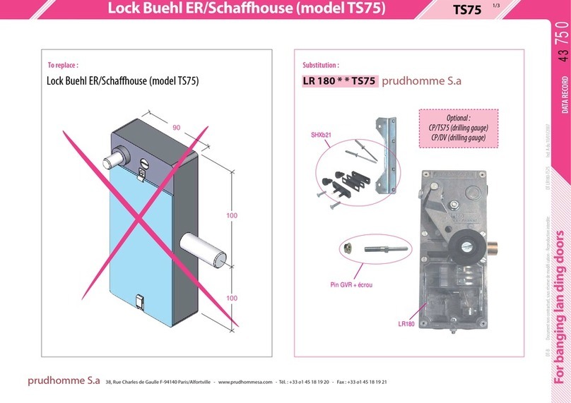
prudhomme
prudhomme TS75 instructions
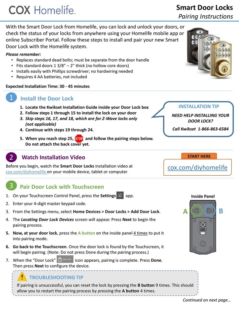
COX
COX Homelife Pairing Instructions

Assa Abloy
Assa Abloy 8788 Installation instruction
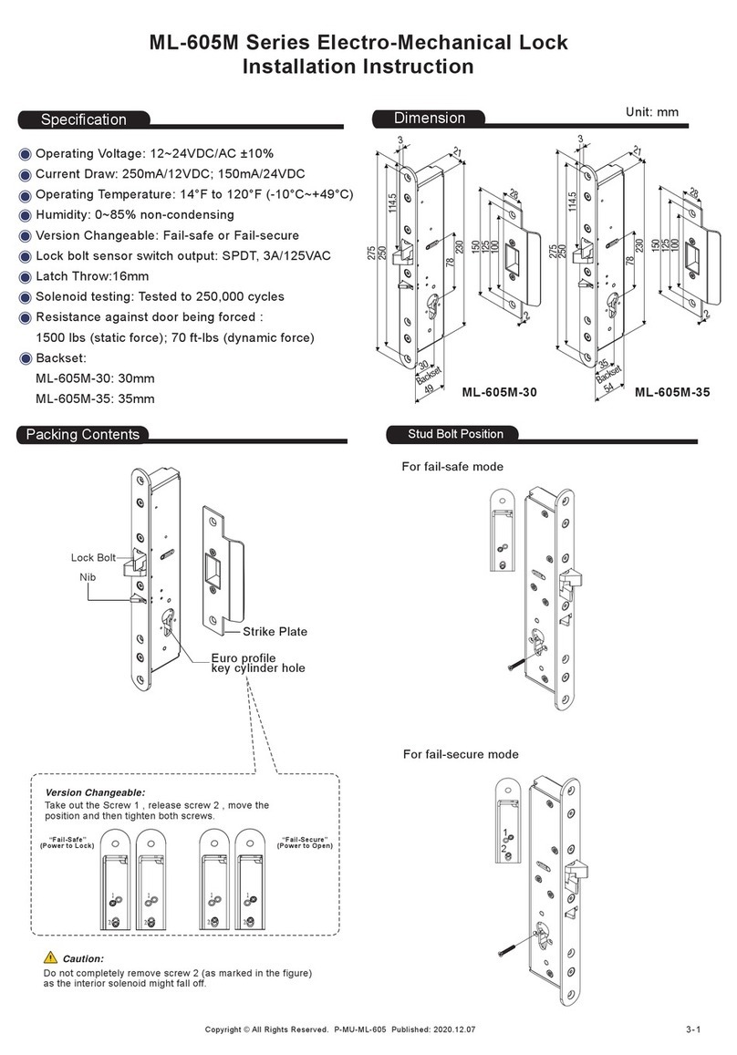
ANXELL
ANXELL ML-605M Series Installation instruction

Kwikset
Kwikset WEISER Tavaris 800TVH LIP 26 SMT installation guide
Assa Abloy
Assa Abloy Corbin Russwin ED3400 Series installation instructions
