Assa Abloy 8788 User manual
Other Assa Abloy Door Lock manuals
Assa Abloy
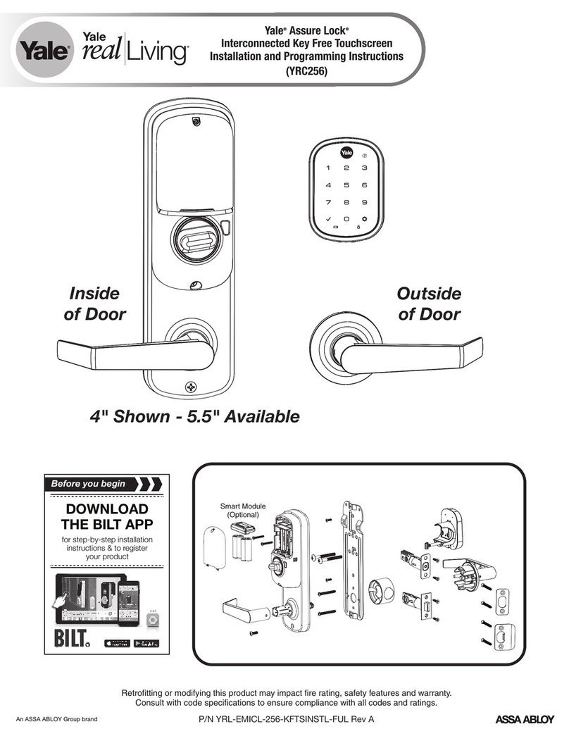
Assa Abloy Yale Real Living Assure Lock YRC256 Technical specifications
Assa Abloy
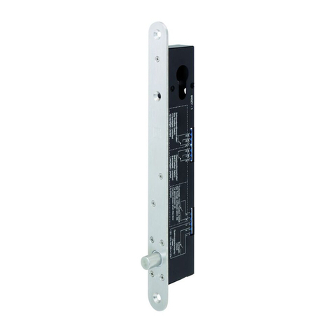
Assa Abloy effeff 843ZY User manual

Assa Abloy
Assa Abloy VERSO CLIQ V532 User manual
Assa Abloy
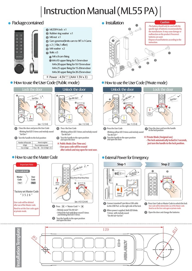
Assa Abloy ML55 PA User manual

Assa Abloy
Assa Abloy HES 9400 Operating instructions
Assa Abloy
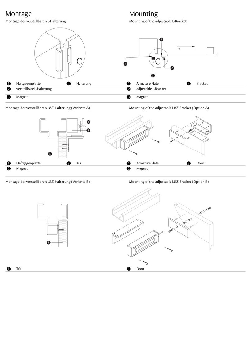
Assa Abloy effeff MAGAC-L Series User manual
Assa Abloy
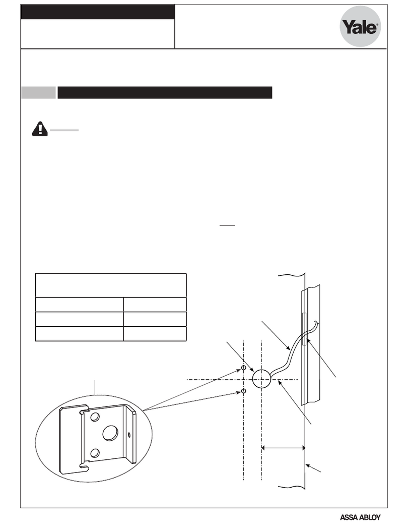
Assa Abloy Yale 6100 User manual

Assa Abloy
Assa Abloy IKON eCLIQ SPARK N112 User manual

Assa Abloy
Assa Abloy effeff 843 User manual

Assa Abloy
Assa Abloy Sargent 10G13 User manual
Assa Abloy
Assa Abloy Yale Assure Lock with Wi-Fi User manual

Assa Abloy
Assa Abloy Arrow Revolution U4A-YRHCPZW0 Technical specifications
Assa Abloy
Assa Abloy Sargent PE8893 User manual

Assa Abloy
Assa Abloy Sargent IN220 User manual

Assa Abloy
Assa Abloy MSL mFlipLock basis User manual
Assa Abloy
Assa Abloy Yale YD-01-CON-NOMOD User manual
Assa Abloy
Assa Abloy Lockwood Selector Series User manual
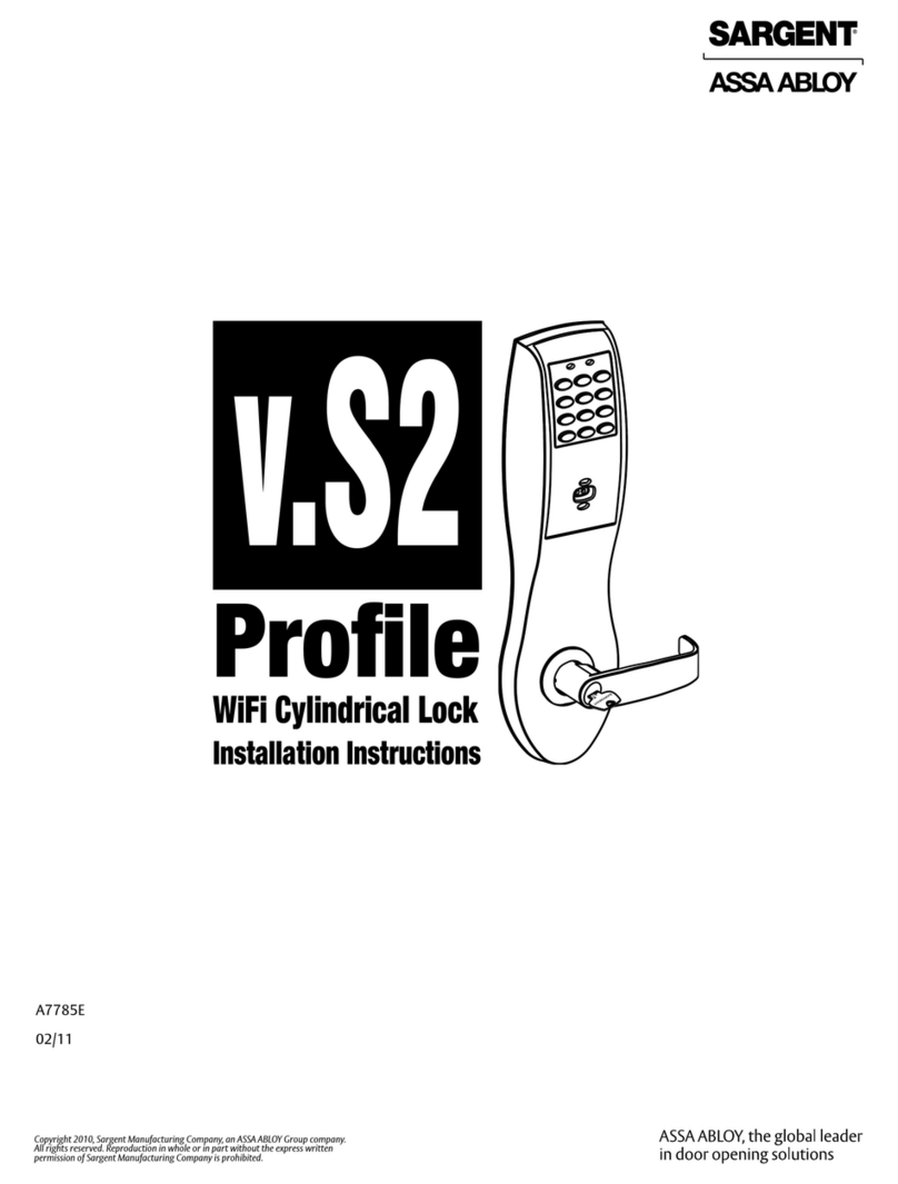
Assa Abloy
Assa Abloy SARGENT Profile Series User manual
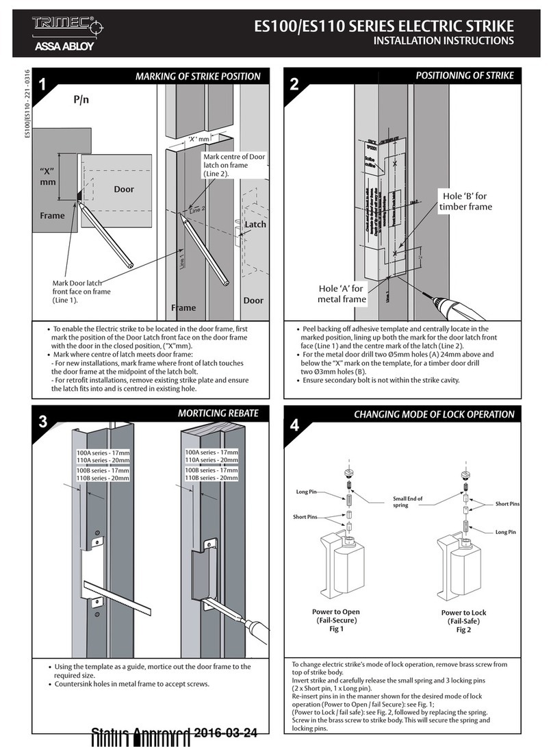
Assa Abloy
Assa Abloy ES100 Series User manual

Assa Abloy
Assa Abloy 1489 User manual
Popular Door Lock manuals by other brands

SCOOP
SCOOP Pullbloc 4.1 FS Panik Assembly instruction

Yale
Yale MORTISE 8800 SERIES installation instructions

Siegenia
Siegenia KFV AS3500 Assembly instructions

Saflok
Saflok Quantum ädesē RFID installation instructions

ArrowVision
ArrowVision Shepherd 210 installation manual
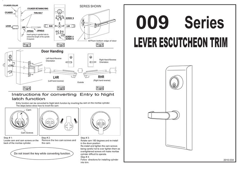
Baldwin
Baldwin 009 Series quick start guide
