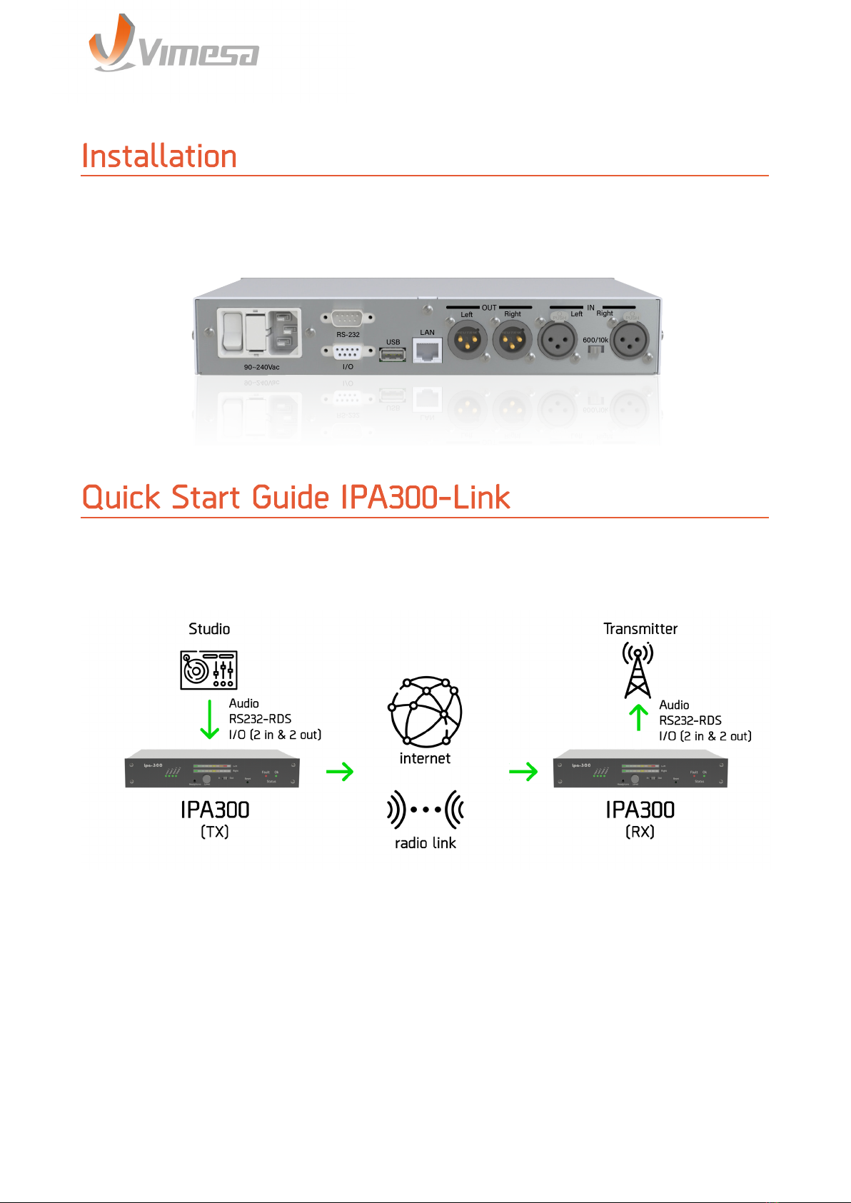
Vimesa IPA300-Link User manual

IPA300-Link
USER MANUAL - UPDATED FEBRUARY 2022
User Manual
Audio Over IP Link

AUDIO INPUTS Connector type XLR Female
Balanced Input 600/10 kOhm input Impedance
Clipping Level +12dBu
Frequency Response (-3dB) ± 0.1dB (20Hz...20kHz)@44.1 kHz sample rate
Signal to Noise Ratio (SNR) ≤ -70dB
Stereo Crosstalk ≤ -50dB
Total Harmonic Distortion (THD)@-3dBfs ≤ 0.05%
Input Level Software Adjustable from Web Page from -18dB to +9dB step: 1.5dB
AUDIO OUTPUTS Connector type XLR Male
Balanced Output 15 kOhm
Output Level Adjustable from Web Page from -90dBu to +6dBu
Full Scale Output Voltage +9dBu, 8Vpp
Frequency Response (-3dB) ±0.1 dB (20 Hz...20 kHz)@ 48kHz sample rate
Signal to Noise Ratio (SNR) ≤ -70dB
Stereo Crosstalk ≤ -60dB
Total Harmonic Distortion (THD)@-3dBfs ≤ 0.03%
RS-232 INTERFACE Connector DB9 Female
Type & Speed Asynchronous - 300~230.400 Baud
Purpose RS-232 Remote Tunneling
DIGITAL I/O Number of inputs 2-Optoisolated
Number of Outputs 2-Relay Contact
Connector type DB9 Female
ETHERNET Interface 10/100Mbps auto
Connector type RJ45 with Link & Activity LEDs
Protocols TCP/IP, UDP, RTP, DHCP
MISCELLANEOUS Headphone Stereo Jack 3.5mm
Audio-meter Stereo V-meter 10 LEDs
Level Adjustable from volume knob
ELECTRICAL Voltage 90~240Vac ± 20%
Current 250 mA max.
Connector type IEC-C13/C14
Fuse 500mA delayed
MECHANiCAL Material Aluminum
Weight 600gr
Dimensions (LxDxH) 260x160x44 mm (1U)
Rack Mount Kit Available
TECHNICAL SPECIFICATIONS
Technical Specications

Rev 1.5
USER MANUAL
3
The IPA300 is a solution to stream audio in full-duplex PCM and half-duplex MP3 from a
broadcast studio to a transmitter device in another physical location.
Unidirectional studio-transmitter link (simplex)
1. On the studio device, click “LOCATION” top menu button, select “Studio Encoder” option
and then click on “Apply”.
2.Click on “CONFIGURATION” top menu button, then on “Basic Settings” at the appearing
left menu. Set “Stream Method” to “Push (RTP)”, set the “URL” field to a valid transmiter
IP address/DNS name, set the “Port” field to the port number of the destination device.
Click “Apply” to save the settings.
3. Change now to the transmitter device, click “LOCATION”, select”Transmitter Decoder”
and then click on “Apply”.
Installation
Installation & Use IPA300-Link
Fig. 1: IPA300 rear view
Quick Start Guide IPA300-Link
Fig. 2: Simple studio-transmier link.

Rev 1.5
USER MANUAL
4
4. Click on “CONFIGURATION” and the on “Basic Settings”. Set “Stream Method” to “Push
(RTP)”, set the URL to “0.0.0.0” and set the “Port” field to match the value set in point 2,
as destination “Port”. Click “Apply” to save the settings.
Bidirectional studio-transmitter link (full-duplex)
*: for this devices refer to the owner user manual.
1. On the studio device, click “LOCATION” top menu button, select “Studio Encoder/
Decoder” and click “Apply”.
2. On the transmitter device, click “LOCATION”, select “Transmitter Encoder/Decoder”,
and click “Apply”.
3. On both “Studio Encoder/Decoder” and “Transmitter Encoder/Decoder” devices, click
on “CONFIGURATION” menu button and then on “Basic Settings” in the left menu. In
the “OUTGOING STREAM” section set the “URL” and “Port” fields, to IP and port of the
destination (remote) device. In the “INCOMING STREAM” section set the “Port” field as the
local receiving port, that must match the same value of the remote “OUTGOING STREAM”
section “Port” field. The “Stream Method” must be “Push (RTP)” in all four sections. Click
“Apply” to save the settings.
NOTE: for bidirectional (full-duplex) communications, audio format must be set to exactly
the same on both (studio and transmitter) devices.
Unidirectional studio-transmitter link over firewall
This scheme is representing an unidirectional link, where the encoder would stream to
the decoder device that is located behind a firewall. BRTP protocol allows the decoder
Fig. 3: Bidireconal studio-transmier link (full-duplex).

Rev 1.5
USER MANUAL
5
device to announce itself to the studio device, to retrieve (pull) the stream. This scheme
requires that at least the encoder device is reachable from the internet.
1. On the studio side, click “LOCATION” top menu button, select “Studio Encoder” and
click “Apply”.
2. On the transmitter side, click “LOCATION”, select “Transmitter Decoder” and click
“Apply”.
3. On the “Studio Encoder” device, click on “CONFIGURATION” top menu button and then
on “Basic Settings” in the left menu. Set “Stream Method” to “Pull (BRTP), set the “URL”
field to “0.0.0.0” and set the “Port” field to the BRTP listening port and click “Apply”.
4. On the “Transmitter Decoder” device, click on “CONFIGURATION” top menu button and
then on “Basic Settings” in the left menu. Set “Stream Method” as “Pull (BRTP), set the
“URL” field as a valid studio URL/IP, set the “Port” field as the listening port, to match the
“Port” value set for the studio device. Click “Apply” to save the settings.

Rev 1.5
USER MANUAL
6
Conguration and access IPA300-Link
Use an Internet browser to connect to the devices just typing the device IP address in the
browser’s URL line. This IP is shown on the label applied on the device.
Default: 192.168.178.104
Home
The Home page give informations about the status of the stream.
Site Type displays the current configured site type.
Stream Mode displays the current configured event to start streaming to the remote
destination(s).
Keep-Alive displays the current configured keep-alive strategy.
Connection Status displays the actual connection state.
Incoming Stream Status displays the actual Incoming stream status (ON/OFF).
Outgoing Stream Status displays the actual outgoing stream status (ON/OFF):
Fig. 5: IPA300 Homepage

Rev 1.5
USER MANUAL
7
Audio Input is the selected Input source;
Audio Format is the Incoming audio format, or the local audio format if no valid Incoming
RTP payload is detected;
Input/Output Audio level displays the Input (only at Line Interface) and output audio
levels in dB and as visual peak level graphic bar;
Relay 1 to 2 shows the configured event for local relay switch;
Remote Inputs remote inputs state, lime color means active, gray means inactive;
Local Inputs local inputs state, lime color means active, gray means inactive;
Local Relays local relay state, lime color means active, gray means inactive.
Site Type on this drop-down menu select one of the four device working modes for
the device. After reboot (Apply), the “Configuration” section of the WEB UI will show the
device-specific configuration fields only.
NOTE: Selecting an encoder/decoder (full duplex) site type, the audio formats of both
peers must be the same. For the full-duplex link, MPEG audio formats are not supported.
In case of existing MPEG audio settings, the device will reboot and use the μ-law 8kHz
mono audio format as default.
In the Configuration menu it is possible to configure the IPA300 parameters. The menu
is composed by Basic Settings, Network, Streaming, Audio, I/O and Control, Serial and
Security Settings.
Location
Fig. 6: Locaon Page
Conguration

Rev 1.5
USER MANUAL
8
Basic Settings
This section helps to set a fast-startup configuration. It allows the quick configuration of
the first “Outgoing Stream” destination and of the “Incoming Stream” socket.
Outgoing Stream - configures the stream destination URL and Port. .
Default:
192.168.178.106
Incoming Stream - allows to set the local listening IP and Port number.
See “Streaming” manual/help section for further information.
Network
Fig. 7: Basic Sengs Page
Fig. 8: Network Page

Rev 1.5
USER MANUAL
9
This section allows the configuration of the following device settings:
IP Address: Enter the 4 values of the desidered device IP address e.g. “0.0.0.0”
for automatic discovery (in order BOOTP/DHCP/IPzator/AutoIP), “192.168.0.12” for
an internal LAN.
The automatic discovery functions are not executed if a static IP address is set.
To enable automatic discovery but disable certain IP discovery functions set
segment 1,2 and 4 of the IP address to zero. The 3rd segment of the IP is a binary
bitmask, his value can be used to disable one or more discovery function.
For each function you want to disable add the value from the table below:
- “0,0,1,0” to disable AutoIP
- “0.0.2.0” to disable DHCP
- “0.0.4.0” to disable BOOTP
- “0.0.8.0” to disable IPzator
Netmask: set the network subnet mask.
Gateway IP Address: set the IP address of network’s default gateway.
DNS: set the IP address of the name resolution (DNS) server(s).
Syslog Address, Syslog message destination server: if “0.0.0.0” (default) Syslog
messages are broadcasted.
DHCP Host Name: set this field to give a descriptive hostname to identify the
device on the DHCP server.
Web Server Port: set the WEB UI service listening port.
QoS/DSCP: set the Quality of Service/Differenclated Service Code Point (DSCP)
value. If this field is set, QoS in IP header will set to this value while forwarding
packets to destination hosts or routers. This supersedes the IP4 Type of Service
(ToS) value and uses the same byte. Valid values are 0-63, default is 0 (unset).

Rev 1.5
USER MANUAL
10
Streaming
Outgoing Stream - this section is visible for the following site types:
Studio Encoder
Studio Encoder/Decoder
Transmitter Encoder/Decoder
Stream destinations - up to 8 audio destinations can be configured, each one with the
following fields: “Stream Method”, “URL” and “Port”.
Configurable stream methods are:
Push (RTP), to stream to the destination using RTP over UDP.
Multicast, to stream to a multicast group as destination.
Pull (BRTP), to wait for a BRTP request from the remote peer, it will learn the IP and
port from the requesting peer and answer with the audio stream to learned IP destination.
Example:
Fig. 9: Streaming Page

Rev 1.5
USER MANUAL
11
Stream Method URL Port
Push (RTP) 192.168.2.30 4041
Multicast 239.255.231.187 4042
Pull (BRTP) 0.0.0.0 4043
Streaming Mode - allows to select the condition to start streaming to the remote
destination(s).
NOTE: If “Streaming Mode” is set to “never” but a destination IP and port is configured,
device will start to send out the stream in anyway.
Input Trigger Level - triggering Input audio level if “send on level” mode is selected.
Accepted range: 0-32767:
Default: ”1000”.
Inactivity Timeout - streaming starts/stops after this number of milliseconds:
- for “send on Input1/Input2”, if the button is pressed/relased (to prevent accident action);
- for “send on level”, if Input audio signal is more/less than “Input Trigger Level”
Default: ”1000 msec”.
Keep-alive Period - set a period for sending keep-alive to the remote peer.
Incoming Stream - for the incoming audio stream, following fields can be configured:
“Stream Method”, “URL” and “Port”.
Default: ”RTP 0.0.0.0:3030”.
Configurable stream methods are:
- Push (RTP), to listen for a stream using RTP protocol over UDP;
- Multicast, to listen to a multicast IP/group for a multicast stream.
- Pull (BRTP), to use BRTP to send a stream request to the remote peer, this will
learn the IP and port and respond with the stream.
Example:
Stream Method URL Port
Push (RTP) 0.0.0.0 4041
Multicast 239.255.231.187 4042
Pull (BRTP) 192.168.2.31 4043

Rev 1.5
USER MANUAL
12
RTP delay - the RTP decoder keeps constant decoding latency within one frame accuracy.
Set the required delay in milliseconds. To synchronise multiple receivers to the same
stream, set all to the same value.
The delay value should be set large enough to cope with network jitter (difference in
packets delivery time) and possible packet loss. Increase the value if you are experiencing
audio dropout.
Default: ”600 msecs”.
Below a table with the recommended safe settings and Maximum Half and Full Duplex
possible delay [msecs]:
NOTE: “RTP delay” values greater than the maximum limits are rounded down to the
maximum limit value.
Audio Format Rec. Max. HD Max. FD
μ/A-law 8kHz mono 444 4076 2038
μ/A-law 24kHz mono 188 1345 672
PCM 8kHz mono 444 2028 1014
PCM 24kHz mono 188 663 331.5
PCM 16kHz stereo 220 -246
PCM 32kHz stereo 110 - 123
PCM 44.1kHz stereo 80 178 89
PCM 48kHz stereo 72 164 82
MP3 600 * *
*: to be defined
Contact Sync - on a decoder-configured device, sometime the user may need to
synchronize the incoming “remote input” contact closure information with the incoming
audio message, expecting for example a local contact closure synchronized exactly in
a certain moment of the audio message. Enable this setting to have a synchronized
remote input processing.
Default Volume: ”disabled;
NOTE: “Contact Sync” option use the “RTP delay” value for the synchronization, using
an “RTP delay” greater than the maximum possible delay is allowed but will break the
contact synchronization.
Output Trigger Level - triggering output audio level, when relay setting “ON while OUT
audio ON/OFF” is selected. Accepted range: 0-32767.
Default Volume: ”1000”;

Rev 1.5
USER MANUAL
13
Output Inactivity Timeout- inactivity timeout for audio output. Used from the following
features:
- for “ON while OUT audio ON/OFF”, to prevent fast switching of the relay contact..
Default: ”1000 msec”;
Audio
This section allows to configure:
Input Source - choose the desired input source. Line mono and MIC input are mono, the
other settings are stereo.
Default Setting: ”Line Stereo”;
Microphone Gain - select the desired microphone input gain. Visible only for device
types that support the MIC Input.
Output Audio Level - Select the desired output volume, in dB. The maximum volume is
typically 0 dB, however, volume can be up to +6 dB.
Fading Effect - enable a fading effect of the audio when a network connection is new
incoming or re-established.
Format - select the desired audio format.
Sample Rate - select the desired sample rate.
NOTE: Only the available sample rates for the selected audio format will be shown.
MPEG Bitrate Mode - in MPEG formats select between VBR (variable bitrate) and CBR

Rev 1.5
USER MANUAL
14
(constant bitrate).
NOTE: if CBR option is not visible, this means the hardware is not supporting this feature.
MPEG CBR Bitrate- if MPEG CBR encoding is selected the audio compression level (and
consequently the audio quality) is selected by this field. Select the audio bit rate in
kilobits per second. Please note that depending on the sampling rate not all bitrates are
available.
MPEG Bit Reservoir- if MPEG CBR encoding is selected this option allows to use or clear
MPEG Bit Reservoir. This option applies for CBR mode only.
Quality- field is visible for MPEG audio formats only, allows to select the desired MPEG
quality. Higher is the quality, more the MPEG compression get decreased, increasing the
network bandwidth consumption.
I/O and Control
This section allows to configure the handling of the local relays and to set parameters
for sending alarms:
Relay Mode- select the relay working mode.
NOTE: the contact closure information is transfereed from the encoder to the decoder
through the keep-alive packet. If keep-alive option is disabled, no information related to
the Input contacts state will be transferred to the remote device.
SNMP Destinations IP(s)- for alarm sending, set the desired list (colon separated) of
SNMP trap receivers.
SMTP Server IP/DNS- for alarm sending, set the IP address or DNS name of the SMTP
Fig. 11: I/O and Control Page

Rev 1.5
USER MANUAL
15
server.
Local e-mail (FROM:)- FROM mail address, for SMTP alarm service.
Destination e-mail(s) (TO:)- TO mail address, for SMTP alarm service. Multiple e-mail
addresses have to be separated by colon.
Serial
This section allows to configure communication settings for serial ports 1 and 2.
Baud rate, parity, data bits, stop bits and handshake (flow-control) can be set for each
port.
UDP/TCP Control Port for COM1/2- local UDP/TCP port for serial gateway to COM1/2:
- for UDP use a positive value (from 1 to 32768);
- for TCP use a negative value (from -1 to -32768);
- set to 0 to disable the gateway.
Set a value between -32767 and 32768.
Default Port: ”0 (disabled)”;
Fig. 12: Serial Page

Rev 1.5
USER MANUAL
16
Any characters received on this network port will be sent to COM1/2.
Any characters received on COM1/2 will be sent to:
- the latest remote UDP/TCP Host:Port that has already initiated/estalished
connection from the network
- else to the same UDP port number of current destination remote IP (by current
keep-alive info)
TCP Serial Gateway- one device must be the listener (server), the other must try to
connect to the listener device (client). Server side setup: set Keep-alive period as 0, the
device will act as a TCP server, using he configured serial port.
Example: ”-1000”+
Client side setup: set the same TCP port number (-1000) and a keep alive period greater
than 0.
UDP Serial Gateway- set the same serial port (positive value) on both devices.
Security Settings
This section allows to configure the device password and other security settings.
Reset Function- enable or disable the “Reset” function on the Reset hardware button
and on the WEB UI. In order to restart the device press the Reset button once.
Default: ”enabled”;
Fig. 13: Security Sengs Page

Rev 1.5
USER MANUAL
17
Factory Defaults- enable or disable the “Factory Defaults” function on the Reset
hardware button and the web button. If disabled, the only way to revert all settings to
factory defaults is a serial rescue procedure (serial firmware update).
Default: ”enabled”;
Update Function- enable or disable the WEB Update function of the device. If the Update
function is disabled, the only way to update the firmware is to use the serial rescue
procedure.
Default: ”enabled”;
Set Password- this is visible as long as no password is set.
Enter a password (up to 25 characters) and hit the “Apply” button. After the restart you
should close the browser window and open a new browser window. You will be asked to
supply user name and password. The user name can be omitted but the password has
to be supplied in order to see the web configuration.
Old Password/New Password- These fields are visible as long as a password is set.
To allow free access (clearing the password) enter the old password and leave the field
“New Password” empty. Enter the old password in the password field above the “Apply”
button as well and then hit the “Apply” button.
After the restart you will not be asked for user name and password any more.
To change the password enter the old password and enter the new password in the field
“New Password”. Enter the old password in the password field above the “Apply” button
as well and then hit the “Apply” button.
After the restart you will be asked for user name and password. The user name can be
omitted but the new password has to be supplied in order to see the web configuration.;

Rev 1.5
USER MANUAL
18
In the “reboot” page it’s possible to restart the device if necessary.
While restarting the device, a countdown appears.
Note: if the
Reboot
function is disabled in
Security Settings
the button “Reboot the device
will be grayed.
The IPA300 can be also rebooted in Hardware mode pressing the RESET button located
on the front panel.
Reboot

Rev 1.5
USER MANUAL
19
IPA300 application is intended to create an audio link between two peers. The link can be
unidirectional or bidirectional, as required from the system application.
Multiple stream destinations are also configurable, and on the decoder side, a service
can play music from the USB stick if no incoming stream is detected.
WEB UI “Location” page allows to select the desired working mode for the device. Specific
use cases for this option are reported in the “Installation&Use IPA300-Link” section.
Once a site type has been configured, only meaningful configuration fields for that site
type will be displayed in the WEB UI configuration page.
Three streaming methods are available:
-Push (RTP) : this method is used to stream the audio directly to one or more destinations
as RTP over UDP. This method is used generally in internal LAN’s or when the receiving
device is reachable over IP address or DNS name. If the receiving device is secured behind
a firewall/router, then it will need a port forwarding rule configured on the router.
- Multicast : this method is used to stream to a multicast group using a multicast IP
address as a destination. Receiving devices must select “Multicast” as stream method,
setting the same multicast IP as listening IP in the URL field.
-Pull (BRTP) : this method allows the use of the special BRTP protocol (revers RTP). The
receiving device must request the stream from the encoding device. The encoder will
learn the IP address and port number of the requesting device and respond with the
stream to the learn IP socket. If the encoder is secured behind a firewall/router, then
it will need a port forwarding rule configured on the router (on encoder site). It allows
to establish an audio link event if the receiving device is secured behind a firewall. The
device that must receive the stream announce itself to the sender device that start
immediately to stream to the destination.
Filed “Streaming Mode” allows to select between multiple stream start conditions. Digital
Inputs or audio level detection can be used to start sending the stream.
General Introduction
Using IPA300 Application
Device Type Selection
Streaming

Rev 1.5
USER MANUAL
20
In unidirectional communications, the device support the following formats: μ-law,
A-law, PCM and MPEG.
In bidirectional communication the device support μ-law, A-law and PCM formats only.
For a broadband streaming, a low bandwidth format as MPEG is suggested.
For each audio format, desired sample rate is selectable.
For MPEG only, a quality setting is available, from 0 to 7. The lower is the quality, the
higher is the compression rate and the lower is the network bandwidth consumption.
The WEB UI shows the device remote inputs, local inputs and local relay states.
A local relay can be configured to work in several ways, see section “I/O and Control” for
further details.
IPA300 supports one serial port. It is possible to configure the serial port baud rate and
eventually the desired UDP or TCP port for the Gateway service.
Through the serial gateway, the data received on the device serial port will be sent over
the network to the remote device and there send out on the serial port. The serial gateway
connection is bidirectional.
The serial gateway port must be specified with the same value on both sides of the link.
See the “Serial” related section /help for further details.
The IPA300 software package offers some secutiy setting to protect the IPA300 device
against manipulation or unauthorised access.
A password for the WEB access can be set. Also some hardware features as the reset
through the device front panel reset button, or the default to factory settings keeping
reset button pressed for 10 seconds, can be disable through the WEB “Security Settings”
section.
Audio Format Selection
Inputs and relays
Serial Ports and Serial Gateway
Security Settings
Table of contents