GENERAL SPECIFICATIONS
Power supply unit ALSCB138V15 has been designed to be used as power unit with backup power energy to
supply unit in alarm systems.
A special care was taken to insulate and protect against accidental contact with dangerous voltages.
The housing is suitable for wall mounting and is designed to safeguard against accidental contact with
dangerous High Voltage.
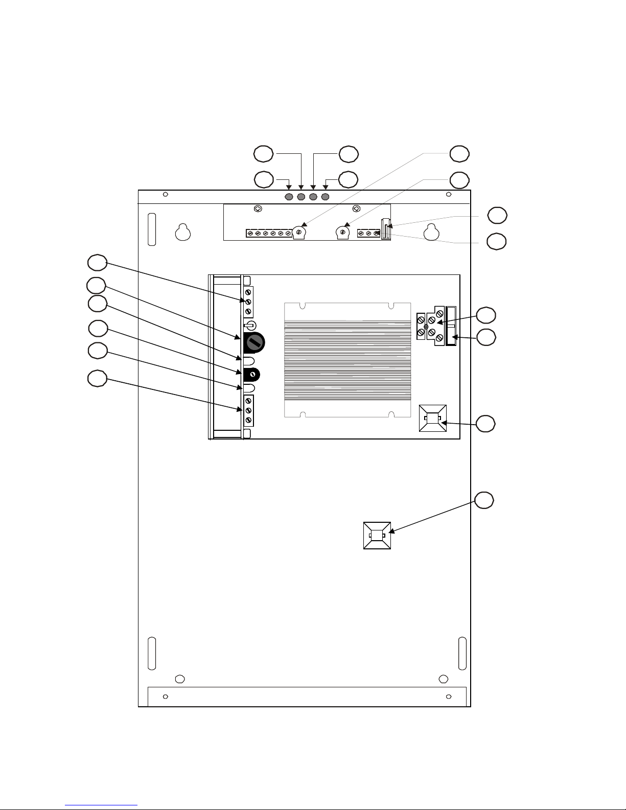
Figure 1 shows the unit with the cover removed, and specifies all input and output terminals, in addition to the
LED indicators.
The unit complies to EN60950 and therefore to EEC73/23.
OPERATIONAL SPECIFICATIONS
This power supply unit consists of:
1 main power supply with stabilised output and short-circuit protected output;
1 control board for mains connection with a fault alarm output
The main power supply is made of terminal block to connect to the AC mains external source and a
protection circuit to the AC connection.
This input is then connected to a double insulated transformer. The rectified power supply voltage is then
connected to a series fold-back type regulator, that stabilises and protects the output voltage that is then
made available to the output terminal.
Every single unit undergoes a burn-in cycle so to grant electrical efficiency of the unit.
All connections between unit and load must be with a shielded cable. The shield must be connected
to GND on power supply side.
.
INSTALLATION
It is highly recommended that this unit is installed by qualified personnel. Installation must be done according
to standard EN60950, concerning electrical safety.
Mount on a stable surface by using screws suitable to bear the weight of the unit in a stable position ( see
section TECHNICAL CHARACTERISTICS).
Drill holes using the template provided. The diameter of the holes must be suitable for 6 mm diameter screws
minimum.
The cover is opened by removing the 4 front screws, fix the back of the power supply to the wall and connect
as shown in Figure 1.
The installation of security switch is recommended on the 230Vac input line. The device should be differential
(ea id<30 mA) so as to provide earth and short circuit protection.
The security switch should be installed in an easily accessible and convenient place. Undergo all checks on
the unit and replace the cover ensuring the correct positioning of the anti-tamper contact. Use 4 screws to
secure the cover.
This unit can be installed only indoor in environments not affected by water.