AB
A = A’
B = B’
Securely glue together. If coming off during
flight, you lose control of your air plane.
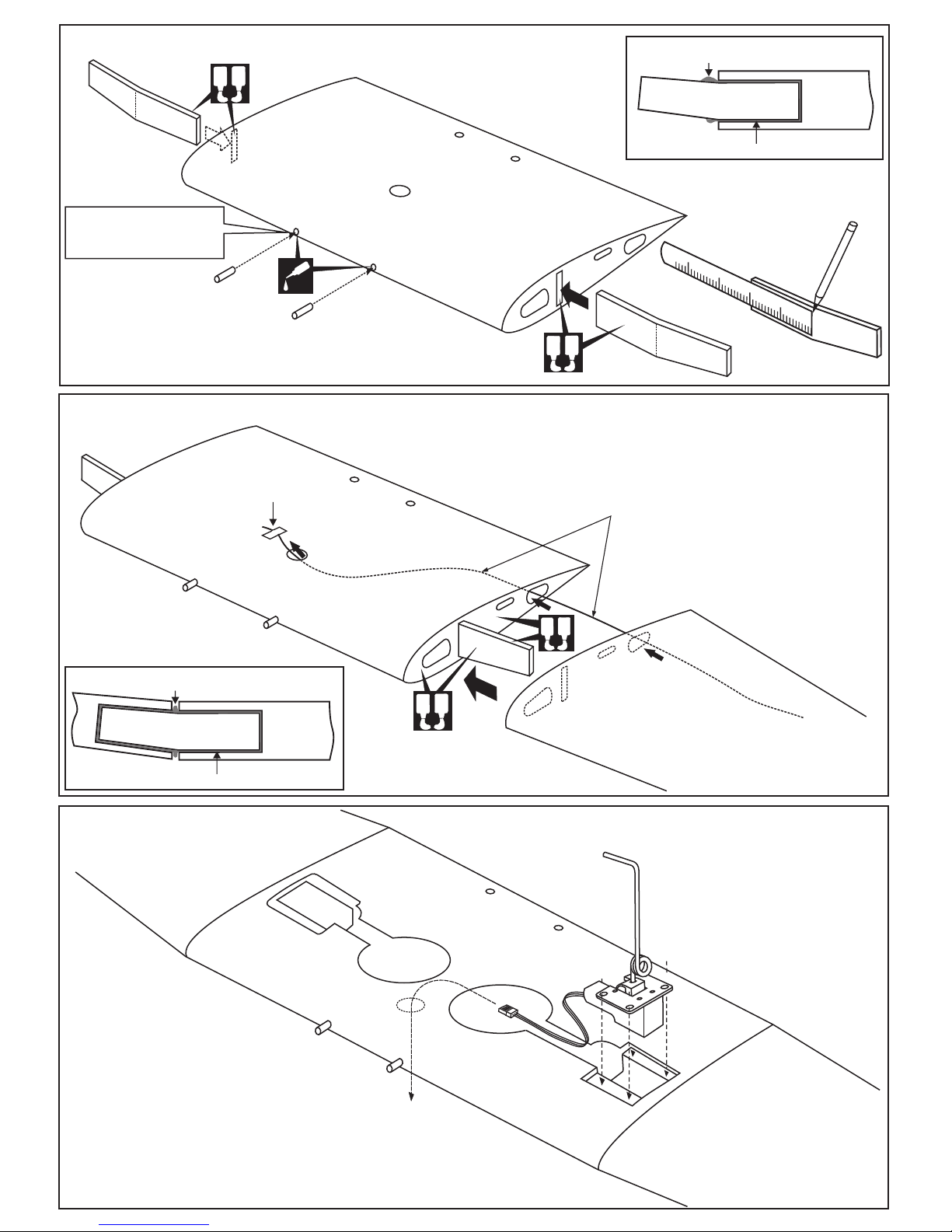
Cut away only the covering
both the top and bottom side
Both the top and
bottom side
Cut away only the covering
both the right and left side
BB’
1-Trial fit the horizontal stabilizer in place .
Check the alignment of the horizontal
stabilizer. When you are satisfied with the
alignment, use a pencil to trace around the top and
bottom of the stabilizer where it meets the fuselage.
2-Remove the horizontal stabilizer from the fuselage. Using the
sharp hobby knife, carefully cut away the covering inside the
lines which were marked above.
3-Spread epoxy (30 minute) onto the top and bottom of the horizontal stabilizer
along the area where the covering was removed and to the fuselage where the
horizontal stabilizer mounts.
4-Install the horizontal stabilizer into the fuselage and adust the alignment as described in steep 1.
Vergewissern Sie sich, sauber geklebt
zu haben. Andernfalls konnen Probleme
mit der Flugeigenschaft auftreten!
* WARNING: When removing any covering from the airframe, please ensure that you secure the cut edge with CA or similar
cement. This will ensure the covering remain tight.
AA’
90O90O
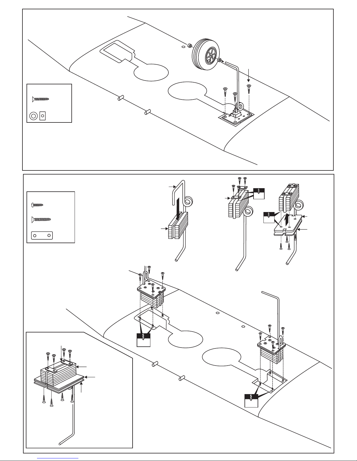
1-Trial fit the vertical stabilizer in place . Check the
alignment of the vertical stabilizer. When you are
satisfied with the alignment, use a pencil to trace
around the right and left of the stabilizer where it
meets the fuselage.
2-Remove the vertical stabilizer from the fuselage.
Using the sharp hobby knife, carefully cut away the
covering inside the lines which were marked above.
3-Spread epoxy (30 minute) onto the right and left and
bottom of the vertical stabilizer along the area where
the covering was removed and to the fuselage where
the vertical stabilizer mounts.
4-Install the vertical stabilizer into the fuselage and
adust the alignment as described in steep 1.
Allow the epoxy to cure before proceeding to next step.
AB
Cut away only the covering both
the right and left side*
C = C’
Both the left and
right side
CC’
Securely glue together. If coming off during flight,
you lose control of your air plane.
IMPORTANT:
Please do not clean off the excess epoxy with strong solvent or pure alcohol, only use kerosene to keep the colour of your
model not fade.
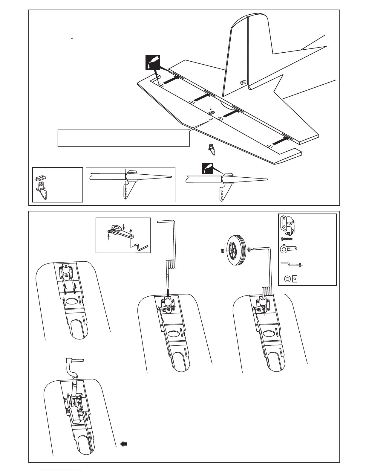
CA
Thin CA
Note: The slots for the control horn installation are pre- cut
at factory.
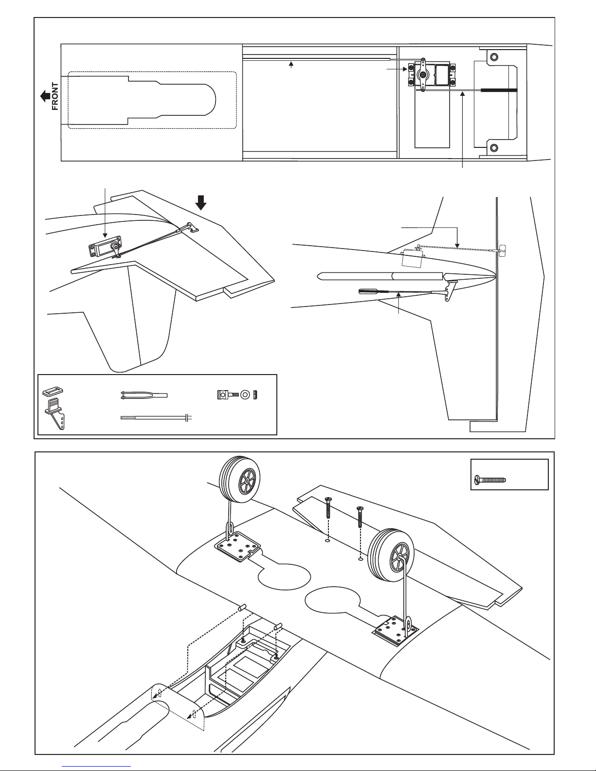
5-Trial fit the hon. Actuate rudder linkage manually it
should not be hard spot. Adjust if necessary.
6-Insert the plate through the foot of the horn.
Bond with thin CA glue.
Plastic control horn
.....................1
FIN RUDDER
9- Horizontal Stabilizer
10- Vertical Stabilizer
CA
Thin CA
The slot for
rudder horn
is pre-cut
at factory