- 9 -
4. Air Sensor
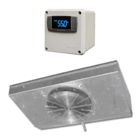
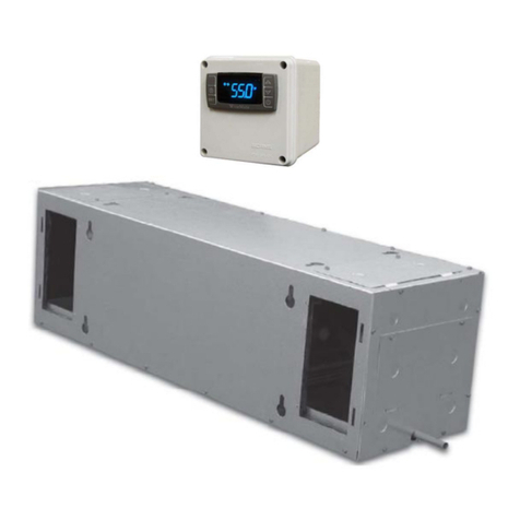
•The air sensor can be located in the wine room 5 ft above the floor or the
return air area, but not the supply air area or air dead area.
•If the temperature controller is mounted outside the wine room but the air
sensor is located inside the wine room, use 18 gauge wires to extend the
air sensor if needed.
5. Piping, Evacuating, Charging and Starting
CAUTION:
•ALWAYS USE THE SUPERHEAT AND SUBCOOLING, PRESSURE
READINGS TO CHARGE REFRIGERANT PROPERLY, THE LISTED
CHARGES ARE FOR REFERENCE ONLY.
•CHARGE 15% MORE REFRIGERANT IN THE SUMMER IF THE UNIT IS
EQUIPPED WITH A LOW AMBIENT CONDITION KIT.
NOTES:
•THE LINE CONNECTION SIZES OF LIQUID FILTER & INDICATOR, THE
VALVE CONNECTION SIZES OF CONDENSING UNIT AND THE LINE
CONNECTION SIZES OF EVAPORATOR UNIT ARE NOT NECESSARY
THE SAME AS THE ABOVE SPECIFIED LINE SIZES.
•IF THE CONDENSING UNIT IS INSTALLED ABOVE THE EVAPORATOR
UNIT, USE THE SUCTION LINE ONE LISTED SIZE SMALLER.
EXPANSION AND SOLENOID VALVES ARE INSTALLED ON LIQUID LINE.
1) The installation order starts from condensing unit (including receiver and
discharge valve), liquid line filter-drier, moisture-liquid indicator/sight glass,
liquid line, to evaporator unit (including liquid line connection, solenoid
valve, expansion valve, and suction line connection), returning to insulated
suction line, suction valve and then back to condensing unit.
2) Use inverted siphons to prevent liquid from flooding back to the
compressor and aid oil returning to the compressor.
3) Both discharge and suction valves must be in the middle positions during
evacuating and charging.
4) Charge the system after pipe brazing, leak testing and evacuating. Liquid
must always be charged into the hide side.
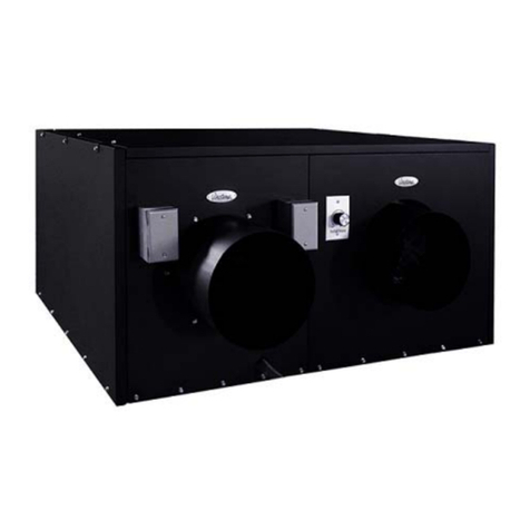
5) It may use fan speed control to adjust the air flow to achieve the specified.
Turn control knob clockwise to the lowest speed position, locate and
adjust the minimum speed setting (on the side or front) with screw driver.
Rotate the setting clockwise to decrease minimum speed or counter-
clockwise to increase minimum speed). The minimum speed should be
adjusted until it supplies the required CFM. The fan will run from this
preset minimum speed to full speed with the control knob at lowest and
highest speed position.


