manuals.online logo
Brands
  1. Home
  2. •
  3. Brands
  4. •
  5. Vinotemp
  6. •
  7. Refrigerator
  8. •
  9. Vinotemp WINEMATE VINO-1500SS User manual

Vinotemp WINEMATE VINO-1500SS User manual

VINO1500SS VINO1900SS
Installer’s Instruction
Federal law requires that WINEMATE split cooling systems be
installed by an EPA certified refrigeration technician.
WINEMATE split system is shipped as components and is ready for use only
after a certified refrigeration technician has properly installed, evacuated,
charged and tested the system. Proper installation is critical. Vinotemp can only
warrant the quality of the components. The installation and proper operation of
the system must be warranted by the installer. Installation of the system must be
done in accordance with all state and local building electrical codes.
The condensing unit and evaporator unit are connected by a liquid line and an
insulated suction line that are supplied by the installer. These lines must be
properly sized for the distance between the two units. After the units and the lines
are installed, the system must be pressure tested. If no leaks are found,
evacuate and charge system. Refrigerant amount will vary depending on the
length of line set.
1. Condensing Unit
•Place the condensing unit in a properly ventilated
location. If it is not, heat exhausted by the condensing
unit will build up and the cooling system will not
operate properly.
•Condensing unit shall be elevated to avoid possible
flooding and shaded from direct sun. It shall not be
exposed to temperatures higher than 110 °F or lower
than 50 °F (optional low ambient kit available).
•Leave minimum 5 feet clearance for the exhaust side and leave minimum
1 foot clearance for the fresh air intake side.
- 1 -
CAUTION:
DO NOT SWITCH ON THE COMPRESSOR IF THE CONDENSING UNIT IS
EQUIPPED WITH A LOW AMBIENT CONDITION KIT UNTIL THE UNIT HAS
BEEN PLUGGED IN FOR 24 HOURS.
2. Valve Operation (Condensing unit)
BACK POSITION FRONT POSITION MIDDLE POSITION
Fig. 1 ROTALOCK Valve Operation
BACK POSITION FRONT POSITION MIDDLE POSITION
Fig. 2 Base Valve Operation
1 - Process & Manometer; 2 - Receiver/Compressor Suction
3 - Liquid/Suction Line; 4 - Pressure Control
Back Position: Process and manometer port closed for normal operation
Front Position: Connection to liquid or suction line closed
Middle Position: All ports open for evacuation, charge and manometer reading
3. Evaporator Unit
•The WM-15SFC evaporator units shall be installed for ceiling mount with
the air supply towards horizontally and air return on the bottom.
•The WM-19SFC evaporator unit shall be installed for wall mount with the
air supply towards top and air return on the sides.
•Supply and return air flow from the evaporator unit shall be unobstructed
for at least 1 foot.
- 2 -
•There is a gravity drain line and the unit shall be installed level or with a
slight angle toward the drain connection. If rise-up is needed, a
condensation pump must be used.
4. Refrigeration Piping, Evacuating, Charging and Starting
CAUTION:
•ALWAYS USE THE SUPERHEAT AND SUBCOOLING, PRESSURE
READINGS TO CHARGE REFRIGERANT PROPERLY, THE LISTED
CHARGES ARE FOR REFERENCE ONLY.
•CHARGE 15% MORE REFRIGERANT IN THE SUMMER IF THE UNIT IS
EQUIPPED WITH A LOW AMBIENT CONDITION KIT.
•The installation order starts from condensing unit (including the receiver,
discharge valve), liquid line filter-drier, moisture-liquid indicator/sight glass,
liquid line, to evaporator unit (including liquid line connection, solenoid
valve, expansion valve, and suction line connection), returning to insulated
suction line, suction valve and then condensing unit.
•Use inverted siphons to prevent liquid from flooding back to the
compressor and aid oil returning to the compressor.
•Charge the system after pipe brazing, leak testing and evacuating.
•The subcooling at the condensing unit shall be around 10°F. The charge
may be complete when there are no more bubbles forming in the sight
glass.
•The evaporator superheat is set around 8-10 °F at factory.
•The temperature split crossing the evaporator shall be 8-10°F at 55°F
wine room temperature.
•Suction pressure: 30-35 psig
•Head pressure: 125-150 psig at 70 -90 °F ambient temperatures.
The line sizes and refrigerant charges are listed as follows.
MODEL REFRIGERATION
LINES LIQUID
LINE SUCTION
LINE DRAIN
LINE CHARGE
VINO-1500SS <= 50 FT 1/4"
OD 3/8” OD 1/2” OD R134a/
15 OZ
VINO-1900SS <=50 FT 1/4"
OD 3/8” OD 3/8” OD R134a/
15 OZ
NOTES:
•THE VALVE CONNECTION SIZES OF CONDENSING UNIT AND THE LINE
CONNECTION SIZES OF EVAPORATOR UNIT ARE NOT NECESSARY
THE SAME AS THE ABOVE SPECIFIED LINE SIZES.
•IF THE CONDENSING UNIT IS INSTALLED ABOVE THE EVAPORATOR
UNIT, USE THE SUCTION LINE ONE LISTED SIZE SMALLER.
- 3 -
•EXPANSION VALVE AND SOLENOID VALVE ARE INSTALLED ON
LIQUID LINE.
5. Pressure, Superheat and Subcooling Readings
CAUTION:
THE VALVES MUST BE IN THE MIDDLE POSITIONS TO READ PROPERLY.
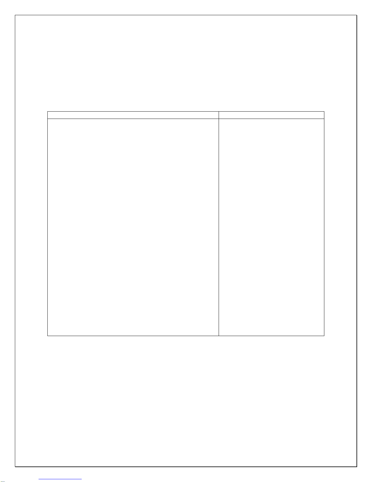
Complaint Possible Causes
a. High suction pressure and low head pressure
b. High suction pressure and low head pressure
Low superheat and low subcooling
c. High suction pressure and high head pressure
Low superheat and high subcooling
d. High to normal suction pressure and high head pressure
Low subcooling
e. High suction pressure and high head pressure
Low subcooling
f. High suction pressure and high head pressure
High superheat
g. Low suction pressure and low head pressure
High superheat and low subcooling
h. Low suction pressure and low to normal head pressure
High superheat and high subcooling
i. Low suction pressure and low head pressure
Low subcooling
j. Low suction pressure and low head pressure
Low superheat and low subcooling
k. Low suction pressure and low to normal head pressure
High superheat and normal to high subcooling
l. Low suction pressure and normal head pressure
High superheat and normal subcooling
m. Low suction pressure and high head pressure
High superheat and high subcooling
n. Low suction pressure and high head pressure
High superheat and high subcooling
o. low to normal suction pressure and high head pressure
High to normal superheat and high subcooling
a. Compressor may be bad
b. Expansion valve opened, too
much oil
c. Overcharge
d. Non-condensable gas
e. Air restricted, dirty condenser,
bad condenser fans
f. High room temperature, high
evaporator load
g. Undercharge
h. Liquid line restricted after
receiver, solenoid valve
restricted
i. Suction line restricted
j. Air restricted at evaporator,
evaporator iced
k. Evaporator restricted
l. Expansion valve restricted
m. Both evaporator and condenser
restricted
n. Liquid line restricted before
receiver
o. Condenser restricted
6. Use of the adjustable pressure control (if applicable for pump-down)
Suction pressure setting: Cut out=5 psig; Cut in=25 psig; Differential=20 psig
Head pressure setting: Cut out=230 psig; Cut in=150 psig; Differential=80 psig
It may need to adjust the setting in the field to get the right cycle time.
- 4 -
A. Single Control
Fig. 3 Single Adjustable Pressure Control
B. Dual Control
Fig. 4 Dual Adjustable Pressure Control
7. Use of the encapsulated pressure control (if applicable)
Fixed suction pressure setting: Cut in = 32 psig; Cut out = 10 psig
- 5 -
8. Use of the condenser fan control (if applicable for low ambient kit)
Head pressure setting: Cut in=170 psig; Cut out=120 psig; Differential=50 psig
It may need to adjust the setting in the field to prevent short fan cycle.
9. Use of the crankcase heater (if applicable for low ambient kit)
The crankcase heater is installed around the lower part of the compressor and
shall be turned on all the time. The heater is self-regulated.
CAUTION:
TURN OFF THE COMPRESSOR SWITCH BEFORE POWER THE
CONDENSING UNIT. ONLY TURN ON THE COMPRESSOR AFTER THE
UNIT HAS BEEN POWERED FOR 24 HOURS.
10.Condensing Unit Troubleshooting
Unit not running
a. Incorrect power supply
b. Incorrect or loose wirings
c. Failed components
d. Liquid refrigerant in the compressor
e. Low pressure switch shutting down the system
a. Check for proper voltage
b. Check all wirings and connections
c. Check start relay, start capacitor, overload
protector, compressor.
d. Call service for OEM information
e. Check for system restriction or low
refrigerant

Other manuals for WINEMATE VINO-1500SS

1

This manual suits for next models

1

Other Vinotemp Refrigerator manuals

Vinotemp VT-DS15SB90-OR User manual

Vinotemp

Vinotemp VT-DS15SB90-OR User manual

Vinotemp VT-12TEDi User manual

Vinotemp

Vinotemp VT-12TEDi User manual

Vinotemp VT-ODSBREF User manual

Vinotemp

Vinotemp VT-ODSBREF User manual

Vinotemp VT-28-TEDS User manual

Vinotemp

Vinotemp VT-28-TEDS User manual

Vinotemp BC-58 User manual

Vinotemp

Vinotemp BC-58 User manual

Vinotemp 100 User manual

Vinotemp

Vinotemp 100 User manual

Vinotemp WineMate VINO1500CD User manual

Vinotemp

Vinotemp WineMate VINO1500CD User manual

Vinotemp VT36TS User manual

Vinotemp

Vinotemp VT36TS User manual

Vinotemp Wine-Mate VINO2500-2500SSR Guide

Vinotemp

Vinotemp Wine-Mate VINO2500-2500SSR Guide

Vinotemp VT-OUTDOORREF User manual

Vinotemp

Vinotemp VT-OUTDOORREF User manual

Vinotemp SC-130N User manual

Vinotemp

Vinotemp SC-130N User manual

Vinotemp VT-32BSW User manual

Vinotemp

Vinotemp VT-32BSW User manual

Vinotemp VT-REFOUT15 User manual

Vinotemp

Vinotemp VT-REFOUT15 User manual

Vinotemp SC-1 User manual

Vinotemp

Vinotemp SC-1 User manual

Vinotemp VT-32BCSB User manual

Vinotemp

Vinotemp VT-32BCSB User manual

Vinotemp WINEMATE VINO-1500SS User manual

Vinotemp

Vinotemp WINEMATE VINO-1500SS User manual

Vinotemp WINE-MATE VINO-2500SSR User manual

Vinotemp

Vinotemp WINE-MATE VINO-2500SSR User manual

Vinotemp VT-DSODREF User manual

Vinotemp

Vinotemp VT-DSODREF User manual

Vinotemp VT-21-TEDS2Z User manual

Vinotemp

Vinotemp VT-21-TEDS2Z User manual

Vinotemp WINE-MATE VINO-1500SSL Guide

Vinotemp

Vinotemp WINE-MATE VINO-1500SSL Guide

Vinotemp WINE-MATE VINO4500DS Guide

Vinotemp

Vinotemp WINE-MATE VINO4500DS Guide

Vinotemp Brama BR-30GDRFZ User manual

Vinotemp

Vinotemp Brama BR-30GDRFZ User manual

Vinotemp WINE-MATE VINO2500SSH Guide

Vinotemp

Vinotemp WINE-MATE VINO2500SSH Guide

Vinotemp WINE-MATE VINO-1500SSW Guide

Vinotemp

Vinotemp WINE-MATE VINO-1500SSW Guide

Popular Refrigerator manuals by other brands

Klarstein 10032198 instructions

Klarstein

Klarstein 10032198 instructions

LG GR-M802HMHM owner's manual

LG

LG GR-M802HMHM owner's manual

Maytag MTB2254EEW User instructions

Maytag

Maytag MTB2254EEW User instructions

Samsung RB195** user manual

Samsung

Samsung RB195** user manual

Dometic RM211 Operating and installation instructions

Dometic

Dometic RM211 Operating and installation instructions

Electrolux ER2640C instructions

Electrolux

Electrolux ER2640C instructions

Electrolux ERT1000AOW user manual

Electrolux

Electrolux ERT1000AOW user manual

Bosch KFN96VPEAL user manual

Bosch

Bosch KFN96VPEAL user manual

Electrolux LNT5ME36U1 user manual

Electrolux

Electrolux LNT5ME36U1 user manual

IFB RFFT446-EDWDLS/PW user manual

IFB

IFB RFFT446-EDWDLS/PW user manual

LG LFX25973ST owner's manual

LG

LG LFX25973ST owner's manual

Electrolux EW28BS71I Series Energy guide

Electrolux

Electrolux EW28BS71I Series Energy guide

Frigidaire FTE5200SBRE operating instructions

Frigidaire

Frigidaire FTE5200SBRE operating instructions

Hisense RD-60WC1STA/USE-002 Service manual

Hisense

Hisense RD-60WC1STA/USE-002 Service manual

Tefcold UF50G user manual

Tefcold

Tefcold UF50G user manual

Beko RSSA215K20W Instructions of use

Beko

Beko RSSA215K20W Instructions of use

Midea UR-BD390WE-ST Service manual

Midea

Midea UR-BD390WE-ST Service manual

Grundig GFTU 13130 N user manual

Grundig

Grundig GFTU 13130 N user manual

manuals.online logo
manuals.online logoBrands
  • About & Mission
  • Contact us
  • Privacy Policy
  • Terms and Conditions

Copyright 2025 Manuals.Online. All Rights Reserved.