Vintage view W Series User manual
W Series Frame Extension Bracket
Installation Instructions for FCF-2EX
• (2) FCF-2EX Pieces • Phillips Head Driver
• Drill
• Level
• Metal Cutting Saw
• Tape Measure
• Metal File
• Pencil
Starter Kit Included Parts Required Tools
Fasteners: There are pre-drilled mounting holes in each mounting plate. Appropriate fasteners for surface
must be utilized in every mounting hole for proper installation. Fasteners for securing racks to the frames are
provided, but hardware for attaching the frames to the floor and ceiling are not. We recommend the following
fasteners for these surfaces:
• Drywall installations should attach to joists or wood backing when available with a #8 X 1-1/2” course
thread screw or larger alternatively, use expanding hollow wall anchors with at least #8 screw size
• Wood surfaces use #8 X 1-1/4 course thread screws or larger
• Concrete, Brick or Stucco: 3/16” x 1 ¼” masonry screw or #8 x 1 ¼” screw with appropriate size
expanding concrete anchor
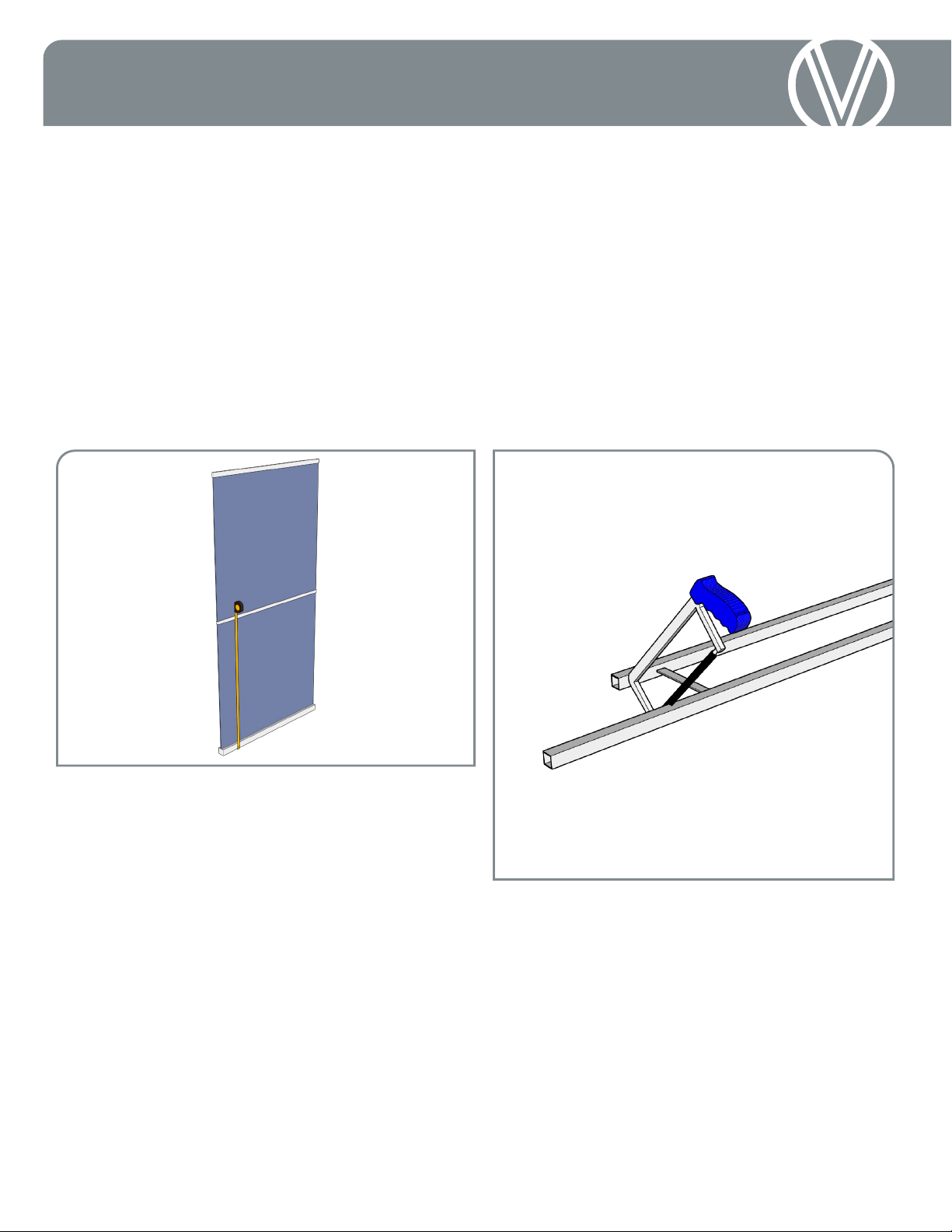
Figure A
1. Measure Lower Section Height: Measure
the distance from the floor to the centerline where the
Extension Bracket will attach (Figure A). Subtract 3/16”
(4.8mm) from the measured height (to allow for the
thickness of the bottom mounting plate and half of the
extension bracket) and mark the calculated distance on
both legs of the frame.
Note: If the calculated measurement aligns with one
of the cross members, cut 2” (52mm) off the end of the
frame and then mark the cut lines, measuring away from
the fresh cut.
2. Cut the Lower Section: Using a reciprocating
saw, band saw or hack saw with the appropriate blade;
squarely cut both legs of the frame at the marks from
Step 1 (Figure B). With a metal file, carefully remove
any resulting burrs from the cuts.
Note: An abrasive cut-off saw should not be used, as
the heat generated is likely to damage the finish of a
Wall Series Frame.
3. Assemble the Lower Frame: Insert the
C-channel of the Extension Brackets into the end of
one frame section and ensure that they fully seated.
The horizontal plate should be flush against the end
of the frame (Figure C). Install the bottom mounting
plate option into the opposite end of the frame by
sliding the C-channel into the frame as shown below
and securing with a self-drilling screw through the
side of the frame.
Figure B

Instructions: 2” Extension Bracket
4: Install Lower Frame: Following the directions
the W Series Frame and/or any other mounting plate
instructions, install the lower end of the W Series Frame
into the wall or ceiling.
5. Measure Upper Section Height: Hold the
assembled lower section of the frame in place (Figure
D) and refer to the instructions below for the attachment
method corresponding with installation:
Ceiling Mount: Rest tape measure on the horizontal
bracket, between the frame and the wall, and measure
the height of the ceiling. Subtract 1/8 inch (3.2mm)
from the measured distance to accommodate the
thickness of the mounting plates. This applies to standard
Base Plates (FCF-BASE) and Hidden Base Plates (FCF-
HIDDEN). Mark the resulting dimension on the frames
and cut (Figure E), following the procedure in step 2.
Wall Mount: If using the W Series Frame 2”
Standoff Bracket (FCF-2WB), rest tape measure on
the horizontal bracket, between the frame and the
wall, and measure the height to the centerline where
the fasteners will attach. Using that measurement,
add 1/2 inch (12.7mm) to the measured distance.
Mark the resulting dimension on the frames (Figure
E) and cut, following the procedure in step 2.
6: Mount Frame: Slide the upper section into
place over the C-channel of the Extension Bracket,
Repeat steps 1-5 for an additional Extension Bracker
or, following the directions the W Series Frame and/
or any other mounting plate instructions, install the
W Series Frame into the wall or ceiling.
Figure C
Figure D
Figure E
This manual suits for next models
1
Other Vintage view TV Mount manuals


