Vinyl Works SLC User manual

MODEL SLC
A-FRAME LADDER CONVERSION KIT
( to be used with / for Mode SLA S ide-Lock Ladder)
ASSEMBLY INSTRUCTIONS
IMPORTANT INSTRUCTIONS: Read all instructions completely to become familiar wit assembly, safety and proper use of t is
product. Failure to follow t ese instructions may result in serious personal injury.
TOOLS REQUIRED: 7/16" socket or nut driver, 7/16" open end wrenc , measuring tape, p illips/star & flat ead screwdriver,
ammer, 5/16" & 1/8" drill bit , drill, saw and a pencil
SAFETY INSTRUCTIONS AND PROPER USE
•
••
•
This poo adder (Mode SLI) has a 300 bs. oad capacity - one person - when proper y assemb ed & insta ed
•
••
•
Your above ground poo has SHALLOW WATER - Abso ute y NO DIVING or NO JUMPING into the poo at any time
•
••
•
Fo ow attached instruction for assemb y & insta ation of the ANTI-ENTRAPMENT BARRIER (MUST BE UTILIZED)
•
••
•
For entry / exit of the poo , face adder at a times
•
••
•
This adder is designed for use by one person at a times
•
••
•
Make certain adder is adjusted proper y to poo f oor depth & deck height
•
••
•
Ensure adder base tread is secure y fastened, has no sharp edges and is free of debris so it wi not damage poo iner
•
••
•
Secure adder to deck surface and / or top rai of poo (depending on how deck is constructed in re ation to your poo )
•
••
•
Assemb e and insta adder as per manufacturer’s instructions. Do not deviate from these instructions - injury can occur
•
••
•
Keep top p atform and treads of the adder free from obstructions to avoid possib e injury. Do not secure any items to the adder. Such
objects (eg. thermometer, p ay toys, safety ropes) may create the potentia for tripping or entang ement
•
••
•
This product conforms to the atest revision of the ANSI/APSP standard for aboveground/on ground swimming poo adders
•
••
•
This adder is designed and intended for use as an above ground poo adder on y - do not use for any other purpose
•
••
•
NEVER SWIM ALONE / REMEMBER, NOTHING REPLACES PARENTAL SUPERVISION / SWIM SAFELY
DISASSEMBLY / ASSEMBLY & INSTALLATION
1. This CONVERSION KIT is to be used with / for Model SLA a frame ladder ONLY. The conversion kit is used to convert the a frame
ladder into Model SLI in pool deck ladder for use with / on a pool deck
2. If you have already built your pool deck it would be wise to read ALL the instructions contained within to better familiarize yourself with
the proper and intended use of these products. It may help in designing your deck if it has not yet been built for proper fit & function
3. This instruction assumes that the a frame ladder is already assembled and has been used with your pool. If this is not the case, please
go directly to the assembly instructions for Model SLI in pool deck ladder (later pages included)
4. Refer to Detail 1.1, 1.2 and 1.3 (ladder parts, hardware parts and finished appearance) for assistance during the assembly / disassembly
5. Disconnect both sides of the handrail sets A1+A2 by loosening the three (3) H1 bolts, washers and nuts on each side (see Detail 2). Set
this hardware aside for later use / requirements
6. GENTLY, using a flat head screwdriver, pry the handrails for the EXTERIOR PORTION of the ladder from the top platform (A1 and A2
from platform E). The exterior portion of the a frame ladder is the side that “slides” up and down and locks (portion used outside the
pool) (see Detail 3). It is important to be gentle as not to break the locking tabs that hold these in place. It is easiest to pry from the
bottom, on the underside of the top platform E (see Detail 4). Repeat for both sides of the exterior portion only
7. Once separated, snap the in pool ladder flanges (G1 and G2), packaged with the conversion kit, to the top platform where you had just
removed the A1 and A2 handrails. NOTE: the G1 gets placed where the A1 was removed and the G2 gets placed where the A2 was
removed. Make certain the button lock tabs on the sides of platform E protrude through the flanges and lock securely in place. Secure
using H1 bolts, washers and nuts for both G1 and G2 flanges (see Detail 5)
8. To ensure the top platform E does not come apart from the remaining handrails, predrill a 1/8" pilot hole and secure using the 3/4"
screws provided. Repeat at four (4) locations (see Detail 6)
9. Once you have completed Step 8, please refer to Model SLI instructions included )following pages). This instruction will outline the
proper assembly and use of your desired in pool deck ladder
10. NOTE: additional / extra hardware has been included for your use. Some hardware may be remaining / left over as some hardware
would have been removed from the a frame ladder
11. It is important to follow all instructions closely and do not deviate from t em - serious personal injury may result. Please
review all safety instructions and proper use wit all individuals using t is pool ladder to prevent possible injury
877-VINYL WK www.vinylworkscanada.com
QUESTIONS ? ~ COMMENTS ? ~ CONCERNS ?
Please do not hesitate to contact our customer service if you have any uestions, comments or concerns regarding this or any of our products
(emai cserv@viny workscanada.com)

H1
H2
H3
NUT WASHER
#8x3/4
SCREW
HARDWARE
DETAIL 1.4
IN-POOL - DETAIL 1.3 PARTS - DETAIL 1.2 A-FRAME - DETAIL 1.1
DETAIL 3
DETAIL 4
DETAIL 2
DETAIL 6
EXTERIOR
PORTION
“SLIDE”
SECTION
PRY WITH
FLAT HEAD
SCREWDRIVER
REMOVE H1
HARDWARE
(3 x BOTH SIDES)
DETAIL 5
H1

MODEL SLI
IN-POOL DECK LADDER (With Barrier)
ASSEMBLY INSTRUCTIONS
IMPORTANT INSTRUCTIONS: Read all instructions completely to become familiar wit assembly, safety and proper use of t is
product. Failure to follow t ese instructions may result in serious personal injury.
TOOLS REQUIRED: 7/16" socket or nut driver, 7/16" open end wrenc , measuring tape, p illips screwdriver, ammer, 5/16" drill
bit , drill, saw and a pencil
SAFE Y INS RUC IONS AND PROPER USE
SAFE Y INS RUC IONS AND PROPER USESAFE Y INS RUC IONS AND PROPER USE
SAFE Y INS RUC IONS AND PROPER USE
•
••
•
his pool ladder has a 300 lbs. load capacity
his pool ladder has a 300 lbs. load capacity his pool ladder has a 300 lbs. load capacity
his pool ladder has a 300 lbs. load capacity -
--
- one person
one person one person
one person -
--
- when properly assembled & installed
when properly assembled & installed when properly assembled & installed
when properly assembled & installed
•
••
•
Your above ground pool has SHALLOW WA ER
Your above ground pool has SHALLOW WA ER Your above ground pool has SHALLOW WA ER
Your above ground pool has SHALLOW WA ER -
--
- Absolutely NO DIVING or NO JUMPING into the pool
Absolutely NO DIVING or NO JUMPING into the pool Absolutely NO DIVING or NO JUMPING into the pool
Absolutely NO DIVING or NO JUMPING into the pool
•
••
•
Follow attached instruction for assembly & installation of the AN I
Follow attached instruction for assembly & installation of the AN IFollow attached instruction for assembly & installation of the AN I
Follow attached instruction for assembly & installation of the AN I-
--
-EN RAPMEN BARRIER (MUS BE U ILIZED)
EN RAPMEN BARRIER (MUS BE U ILIZED)EN RAPMEN BARRIER (MUS BE U ILIZED)
EN RAPMEN BARRIER (MUS BE U ILIZED)
•
••
•
For entry / exit of the pool, face ladder at all times
For entry / exit of the pool, face ladder at all timesFor entry / exit of the pool, face ladder at all times
For entry / exit of the pool, face ladder at all times
•
••
•
his ladder is designed for use by one person at all times
his ladder is designed for use by one person at all timeshis ladder is designed for use by one person at all times
his ladder is designed for use by one person at all times
•
••
•
Make certain ladder is adjusted properly to pool floor depth
Make certain ladder is adjusted properly to pool floor depthMake certain ladder is adjusted properly to pool floor depth
Make certain ladder is adjusted properly to pool floor depth
•
••
•
Ensure ladder base tread is securely fastened, has no sharp edges and is free of debris so it will not damage pool liner
Ensure ladder base tread is securely fastened, has no sharp edges and is free of debris so it will not damage pool linerEnsure ladder base tread is securely fastened, has no sharp edges and is free of debris so it will not damage pool liner
Ensure ladder base tread is securely fastened, has no sharp edges and is free of debris so it will not damage pool liner
•
••
•
Secure ladder to deck surface and / or
Secure ladder to deck surface and / orSecure ladder to deck surface and / or
Secure ladder to deck surface and / or top rail of pool
top rail of pool top rail of pool
top rail of pool (depending on how deck is constructed in relation to pool)
(depending on how deck is constructed in relation to pool) (depending on how deck is constructed in relation to pool)
(depending on how deck is constructed in relation to pool)
•
••
•
Assemble and install ladder as per manufacturer’s instructions. Do not deviate from these instructions
Assemble and install ladder as per manufacturer’s instructions. Do not deviate from these instructionsAssemble and install ladder as per manufacturer’s instructions. Do not deviate from these instructions
Assemble and install ladder as per manufacturer’s instructions. Do not deviate from these instructions
•
••
•
Keep top platform and treads of the ladder free from obstructions to avoid possible injury. Do not secure any items to the
Keep top platform and treads of the ladder free from obstructions to avoid possible injury. Do not secure any items to the Keep top platform and treads of the ladder free from obstructions to avoid possible injury. Do not secure any items to the
Keep top platform and treads of the ladder free from obstructions to avoid possible injury. Do not secure any items to the
ladder. Such objects (eg. thermometer, play toys, safety ropes) may create the potential for tripping or entanglement
ladder. Such objects (eg. thermometer, play toys, safety ropes) may create the potential for tripping or entanglement ladder. Such objects (eg. thermometer, play toys, safety ropes) may create the potential for tripping or entanglement
ladder. Such objects (eg. thermometer, play toys, safety ropes) may create the potential for tripping or entanglement
•
••
•
his product conforms to the latest revision of the ANSI/APSP standard for aboveground/on ground swimming pool ladders
his product conforms to the latest revision of the ANSI/APSP standard for aboveground/on ground swimming pool laddershis product conforms to the latest revision of the ANSI/APSP standard for aboveground/on ground swimming pool ladders
his product conforms to the latest revision of the ANSI/APSP standard for aboveground/on ground swimming pool ladders
•
••
•
his ladder is designed and intended for use as an above ground pool ladder only
his ladder is designed and intended for use as an above ground pool ladder onlyhis ladder is designed and intended for use as an above ground pool ladder only
his ladder is designed and intended for use as an above ground pool ladder only
•
••
•
NEVER SWIM ALONE / REMEMBER, NO HING REPLACES PAREN AL SUPERVISION / SWIM SAFELY
NEVER SWIM ALONE / REMEMBER, NO HING REPLACES PAREN AL SUPERVISION / SWIM SAFELYNEVER SWIM ALONE / REMEMBER, NO HING REPLACES PAREN AL SUPERVISION / SWIM SAFELY
NEVER SWIM ALONE / REMEMBER, NO HING REPLACES PAREN AL SUPERVISION / SWIM SAFELY
ASSEMBLY & INSTALLATION
1. Refer to all detailed diagrams within this instruction for assistance during the assembly & installation of this pool ladder. All ladder parts
are identified by a letter & number which is stamped into each ladder part. Look for these markings to assist proper assembly
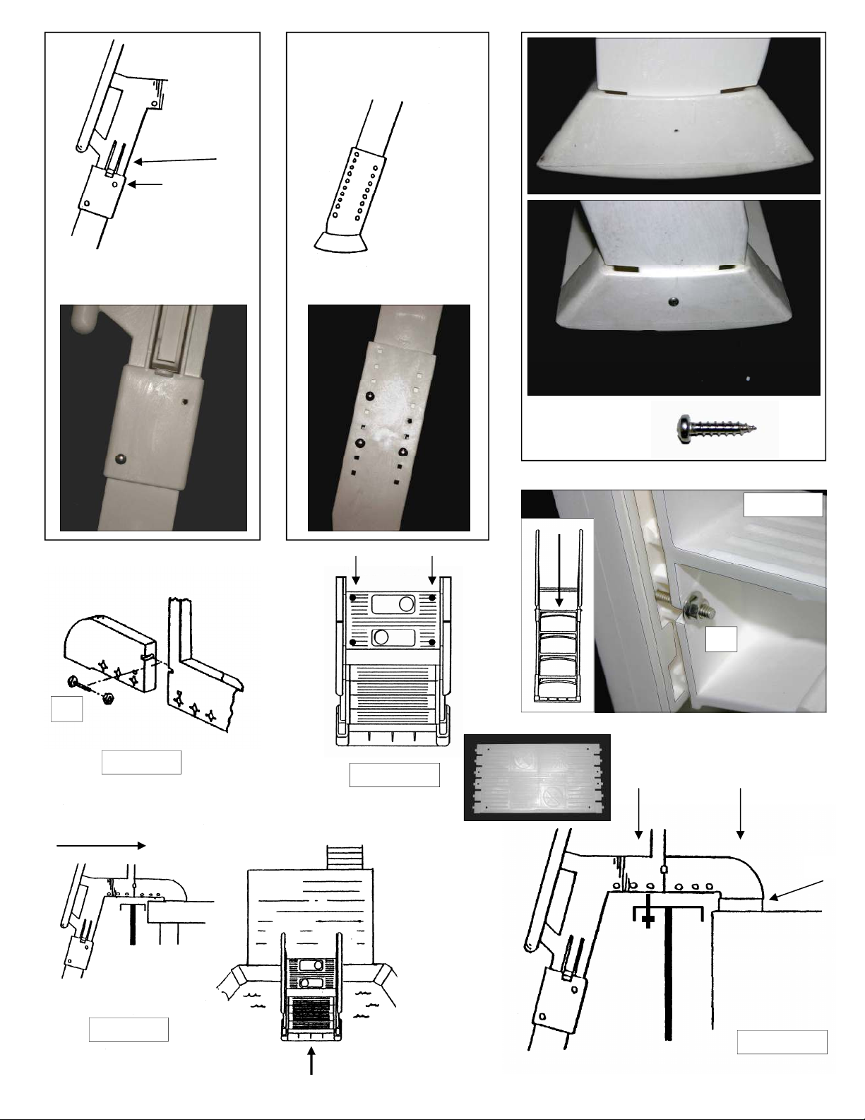
2. Fit top platform (E), with anti skid surface facing upward, into handrails (A1 & A2). Gently tap outside of the handrails so the button lock
tabs protrude through and secure platform in place. See Detail 1.1
3. Attach support legs to the handrail sockets (B1 + A1 & B2 + A2). The ends of all support legs have a raised tab that fits into channels
within the handrail sockets (See Detail 1.1 & 1.4). Secure this connection using only 1 H1 bolt, washer and nut as shown in Detail 2.
Repeat for second support leg. Leave bot inside oles ( H2 ) free of ardware until Step # 7 below
4. You will need to measure the depth of your pool to determine the height adjustment of the ladder. The measurement required is
determined from how your pool deck has been built. The deck surface will either be equal to, lower or higher than the top rail of the pool
(See Detail 1.5). Determine which applies. Measure at the point where you plan to position the ladder as the measurements may vary in
your pool. IMPORTANT if the top surface of your pool deck is equal to or lower than the top rail of the pool (Detail 1.5A or 1.5B),
measure the distance from the bottom of the pool to the top of the top rail. ** When the ladder is completely assembled and installed in
the pool, the top platform of the ladder should rest just above the top rail of the pool so that the ladder itself, not the top rail of the pool,
supports the weight load on the ladder. Thus, add @ ½" to your this measurement. If the deck surface is higher than the top rail of the
pool (Detail 1.5C) simply measure from the bottom of the pool to the top deck surface, nothing needs to be added to this measurement
5. Using the above measurement , determine the position of the adjustable base supports (C1 & C2). There are measurement guides
stamped on the outside of both support legs (48" 56") to assist you in setting the base supports to the proper height. Fit the adjustable
base supports over the ends of the support legs (C1 + B1 & C2 + B2) and align the bolt holes according to the desired height, or slightly
greater than. Secure using only 3 H1 bolts, washers & nuts as shown in Detail 3. Leave remaining hole free of hardware (H2) until Step
# 7 below. Repeat for second adjustable base support of ladder
6. Fit pivotal base tread onto button lock tabs of adjustable base supports (D + C1 & C2). Make certain tabs protrude and lock into the
center opening of the channels in the base tread. The base tread is pivotal and can rotate either direction so the ladder will rest evenly
on the bottom of the pool. To prevent liner damage, ensure base tread is securely fastened, has no sharp edges and is free of any
debris. When rotated to the desired location, secure permanently with screw through each end of the tread (see Detail 4)
7. Stand ladder in the upright position. Fit ladder section (F) into assembled frame by sliding it down the channels of the handrail sets (top
to bottom see Detail 5). Ensure anti skid treads are facing upward and safety writing is facing outward. Pull out locking mechanism
(See Detail 2) so the ladder will slide to the very bottom. Secure the ladder section in place using 4 H2 bolts, washers & nuts in the four
locations where hardware was not used above (Step 2, 3 & 5). IT IS VERY IMPORTANT THESE CONNECTIONS ARE SECURED AS
IT MAKES THE LADDER VERY STABLE. The ladder will be “locked” in place with bolts and cannot slide
8. Attach ladder flanges to both sides of top platform (G1 + E and G2 + E). Gently tap outside of flanges so the button lock tabs of the
platform protrude through and secure flanges in place. Secure using H1 bolts, washers and nuts, from the inside, as shown in Detail 6
9. The assembly of the ladder is now complete. Ensure all hardware is tightened before securing the ladder in place. Test the ladder in the
pool to determine if the height adjustment is properly set. Alter if required
10. Assemble & install ANTI ENTRAPMENT BARRIER as per attached instruction (following page)
877-VINYL WK www.vinylworkscanada.com

QUESTIONS ? - COMMENTS ? - CONCERNS ?
P ease do not hesitate to contact our customer service department if you have any questions, comments or concerns
regarding this or any of our products
To free phone (continenta North America): 1-877-VINYL WK / Other ca s: 905-834-5666
Emai : cserv@viny workscanada.com / Website: www.viny workscanada.com
ASSEMBLY & INSTALLATION (CONTINUED)
•
Position the ladder in the pool at the desired location with the deck. Slide the ladder toward the top rail of the pool or deck (See Detail 7).
Make certain the anti entrapment barrier does not touch the pool wall but is relatively close, reducing the gap / opening between the
barrier and the pool wall to prevent entrapment / children from swimming behind. The top platform of the ladder has 4 possible bolt holes
for securing the ladder in place. Choose the two that best suit your installation (Detail 8A&B). With a pencil, mark the location of the H2
bolts used to secure the ladder to the deck surface (See Detail 8A&B). There are also bolt slots in both ladder flanges G1 & G2. If you
do not have access to the underside of the pool deck you will have to secure the platform and the flanges using lag bolts / screws (not
provided). Drill a 5/16" hole at the marked locations. REMEMBER, use extreme caution when operating power tools around pool water
and ensure debris from drilling does not fall into pool and damage pool liner. Secure ladder in place using H2 bolts, washers and wing
nuts provided or with screws. The ladder can be secured through / to the pool top rail as well, if required (see 8B). Tighten all hardware
•
Should your pool deck surface be lower than the ladder flanges you will need to install a support block between the bottom of the
flanges and the deck surface (Detail 8B). With ladder platform level, just above the top rail, measure the distance between the deck
surface and the bottom of the mounting flanges. Cut a support block and fit between. Ensure the support block is of adequate strength
and is firming secured/fastened to the deck surface. Make certain ladder is securely fastened to the support blocks (for both flanges G1
& G2). See Detail 8B
•
Once in place and secure, ensure ladder is stable and resting on the bottom of the pool. READ OVER AND FAMILIARIZE YOURSELF
AND YOUR FAMILY, OR THOSE USING YOUR POOL, WITH THE SAFETY INSTRUCTIONS AND PROPER USE OF THIS POOL
LADDER REMEMBER, ALWAYS SWIM SAFELY !
G2
A1
B1
C2
A2
D
F
C1
B2
G1
E
LADDER PARTS
DETAIL 1.1 H1
H2
H3
NUT WASHER WING NUT
#8x3/4
SCREW
HARDWARE
DETAIL 1.2 FINISHED
ASSEMBLY
DETAIL 1.3
DETAIL 1.4
HANDRAIL
SOCKET
SUPPORT
LEG
DETAIL 1.5
DECK
DECK
DECK
A B C

LOCKING
MECHANISM
H2 (INSIDE)
LEAVE
EMPTY
FOR NOW
H1
H1
H2
H1
(INSIDE)
LEAVE
EMPTY
FOR NOW
DETAIL 4
DETAIL 2 DETAIL 3
DETAIL 5
H2
DETAIL 8A
DETAIL 6
H1
DETAIL 7
SLIDE LADDER
DECK
DETAIL 8B
BLOCK
H2 BOLTS or SCREWS

IDEN IFY
IDEN IFYIDEN IFY
IDEN IFY
BARRIER
BARRIER BARRIER
BARRIER
PAR S
PAR SPAR S
PAR S
BA
BB
BD
BC
BP
BARRIER
PICKE S
5 PIECES
MODEL SLA / SLI - ANTI-ENTRAPMENT BARRIER INSTRUCTION
1. Fit parts together ( BA + BC & BB + BD ), align small screw holes
and secure with 1/2" barrier screws as shown above
BA + BC
BB + BD
2. Fit sub-assembled BA+BC to back of in
inin
in-
--
-pool ladder section F
pool ladder section Fpool ladder section F
pool ladder section F, behind
top ladder tread/rung. he extended screw tabs on Part BC fit on the
outside of the strengthening ribs of the tread/rung. Slide to top of ribs
and secure in place using a 1/2" screw on both left & right sides.
3. Similar to step 2 above, fit sub-assembled BB+BD to back of in-pool
ladder section F, behind bottom ladder tread/rung. he extended screw
tabs on Part BD fit on the outside of the strengthening ribs of the tread/
rung. Slide to top of ribs and secure in place using a 1/2" screw on both
left & right sides
4. Fit 3 barrier pickets through slots
in BB+BD at bottom & slide up into
slots of BA+BC and secure all with
1/2" screws as shown by arrow
5. Fit 2 barrier pickets through
slots in BB at bottom & slide up
into slots of BA and secure both
with 1/2" screws as shown
6. rim bottom of barrier pickets if
required as not to damage pool
liner. Leave space between
pickets and liner (6" maximum).
Table of contents
Other Vinyl Works Ladder manuals
Popular Ladder manuals by other brands

GIERRE
GIERRE PEPPina AM100 Operating and maintenance instructions

Wenger
Wenger Signature Choral Riser 4-Step Assembly & owners manual

Primal
Primal PVLS-600 Instruction and safety manual

Costway
Costway AT5545 user manual

Confer Plastics
Confer Plastics 6000 quick start guide

Main Access
Main Access 200400T Assembly instructions

TB Davies
TB Davies EuroFold TB Davies User's guide & instructions

Ribimex
Ribimex PRET092 User and maintenance manual

STABILOMAT
STABILOMAT SBT-TL008 Translation of the original instructions

INNOVAPLAS
INNOVAPLAS Lumi-O BILTMOR 5005 installation instructions

Telesteps
Telesteps Prime Series instruction manual

INNOVAPLAS
INNOVAPLAS FIESTA Assembly