Violectric dac v850 User manual

1
DIGITAL-ANALOG CONVERTER
DAC V850 (version 1.1)
USER´s MANUAL

2
Content
Theme Page
About Violectric 3
Safety Instructions 5
The Earth / Grounding Concept 7
Connection / Connectors 9
General 10
Operation 11
The Remote Control Option 19
Programming / default settings 19
Things to know 22
Dismantling / Jumper Setting 24
Technical Data 26
Conformity Statement 27
Warranty 28
Here you can find the USB drivers:
http://www.violectric.de/violectric-others.html
http://violectric-usa.com/downloads

3
Cordial thanks for your decision in favour of a
product !
is a trademark and product line of Lake People
electronic GmbH. Lake People electronic GmbH develops,
manufactures and distributes products in the professional range, for
broadcast, television, airports, exhibition halls, festival venues, theatres,
large-scale installations, private studios and more. In the private sector
as well, Lake People products become increasingly popular due to their
outstanding quality.
The trademark and product line is specially intended to
supply the Hi-Fi and High-End market with its specific requirements.
Who develops equipment ?
devices are exclusively developed in Germany by the
engineers of Lake People electronic GmbH. In doing so, the team of
developers can draw on twenty years of experience and countless
products for the pro-audio domain.
Among others, the first German-made 20-bit A/D and D/A converters
were developed by Lake People in the early nineties of the past century.
Who manufactures equipment ?
devices are exclusively manufactured in Germany by
Lake People electronic GmbH or contractors in the company's vicinity.
Lake People - and by association - put high emphasis
on domestic manufacturing. As well, all component suppliers are chosen
in order achieve the main part of added value inland.

4
How do devices get to the customer ?
devices can be obtained from respective specialist
suppliers. If there is none such accessible regionally, the customer is
supported by transregional distribution partners (google may help...)
and, of course, by Lake People electronic GmbH themselves.
…and if it doesn't work like it should ?
devices are covered by a 24-month warranty. In case of
any malfunction during this period, they can be shipped to the
manufacturer directly. Of course, the client will benefit from
's and Lake People's full technical support even when
warranty has expired. Any technical questions or need for advice is
welcome.
is a subsidiary of
LAKE PEOPLE electronic GmbH
Turmstrasse 7a
D-78467 Konstanz
Fon +49 (0) 7531 73678
Fax +49 (0) 7531 74998
www.violectric.de www.violectric.com
www.lake-people.de www.lake-people.com

5
General Safety Instructions
WARNING
For your protection, please read the following:
Water, Liquids, Moisture:
This appliance should not be used near water or other sources of liquids.
Care should be taken so that objects do not fall and liquids are not spilled into
the enclosure through openings.
Power Sources:
The appliance should be connected to a power supply only of the type described
in the operating instructions or as marked on the appliance.
Grounding:
Care should be taken that this appliance is operated with proper grounding only.
Power Cord:
Power supply cords should be routed so that they are not likely to be walked on
or pinched by items placed upon or against them, paying particular attention to
cords at plugs, convenience receptacles, and the point where they exit from the
appliance.
This unit is equipped with a 3-pole mains cable with a dedicated mains plug for
the Europe, USA, Great Britain or China. In some countries this unit must be
operated with a mains adaptor, supplied by the owner.
Please refer to the table below to connect a mains plug:
OVERVIEW: POWER CORD FUNCTION AND COLORS
CONDUCTOR
COLOR
Alternativ
L
LIVE
BROWN
BLACK
N
NEUTRAL
BLUE
WHITE
E
PROTECTIVE EARTH
GREEN+YELLOW
GREEN
U.K. Mains Plug Warning:
A moulded mains plug that has been cut off from the cord is unsafe.
Discard the mains plug at a suitable disposal facility.
NEVER UNDER ANY CIRCUMSTANCES SHOULD YOU INSERT A DAMAGED OR
CUT MAINS PLUG INTO A 13 AMP POWER SOCKET. Do not use the mains plug
without the fuse cover in place. Replacement fuse covers can be obtained from your local
retailer. Replacement fuses are 13 amps and MUST be ASTA approved to BS 1362.

6
Mains Fuse:
The mains fuse of this appliance is soldered in place and accessible from the
inside only!!
A blown fuse may indicate an internal problem and should be replaced during
qualified servicing or repair work !!
Switchable Power Supply:
Connect this unit to the power source indicated on the equipment rear panel
only to ensure safe operation !!
This unit is provided with an internally settable mains supply for 115 / 230 V AC.
Service / Repair:
To reduce the risk of fire or electric shock, the user should not attempt to service the
appliance beyond the measures described in the operating manual. All other
servicing or repair should be referred to qualified personnel !!
Electromagnetic Compatibility
This unit conforms to the Product Specifications noted as Declaration of
Conformity at the end of this manual. Operation is subject to the following
conditions:
- this device may not cause harmful interferences
- this device must accept any interference received,
including interference that may cause undesired operation
- this device must not be operated within significant electromagnetic field
VOR DEM ÖFFNEN NETZSTECKER
ZIEHEN!! PULL MAINS BEFORE
OPENING!! AVANT D´OUVRIER
RETIREZ LA FICHE MALE!!

7
The Earth / Grounding Concept
General GROUND-LIFT Jumper (accessible from the inside.
Mind the SECURITY INSTRUCTIONS !! ):
Ex-works this jumper is set to the LIFT position.
The internal ground potential is “lifted”by means of this jumper.
As a result, the interconnection for DC voltages and lower frequencies
(< 150 Hz) will be cut. Higher frequencies will be bled off to earth
potential through the RC filter. The LIFT position is helpful in case of
hum or jitter caused by different ground/earth potentials.
Of coarse full electrical protection is granted as the case is always
connected to ground/earth potential !

8
Unfortunately there is no general recommendation how to solve hum
and jitter problems - or even minimize them. The best way to succeed is
to check different options !! In case of balanced cables, it should always
been verified if the shield of the cable is connected to the shell of the
XLR connector. The shell is ALWAYS connected to earth potential when
the connector is inserted !!
Concerning ANALOG inputs and outputs, the relationship between
ground and earth may be modified. Electrical safety is always ensured,
since the earth conductor is permanently connected to the enclosure !!
Please note that with jumpers in LIFT or GROUND position
EMC emission might occur,
for which the user is responsible only !

9
Connection / Connectors

10
GENERAL INFORMATION
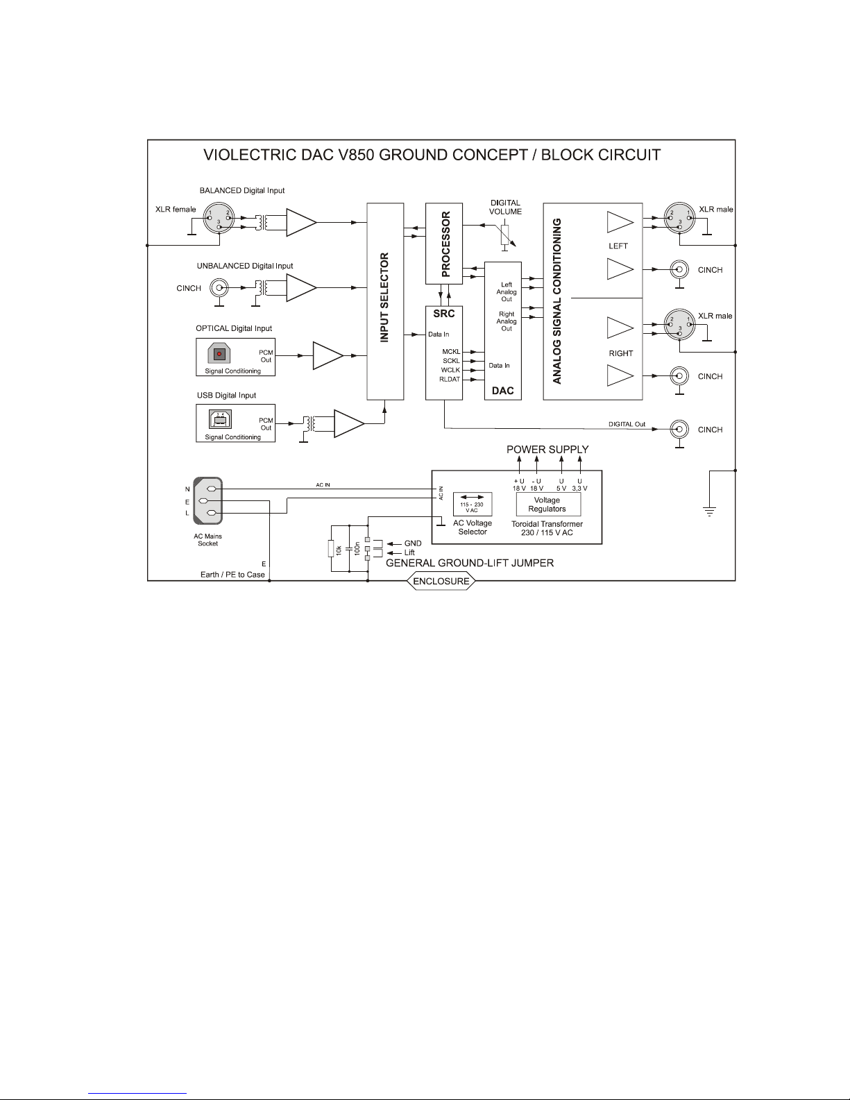
VIOLECTRIC DAC V850 is a top-range D/A converter, distinguished by
its resampling unit, its 32-bit double mono converters and very particular
analog output stages. By means of their specially designed, variable
low-noise and low-distortion circuitry, the DAC V850 fulfils even highest
demands. As an option, the volume control, input selection and the
resampling functionality may be remote controlled.
Features:
- four switchable digital inputs:
- transformer balanced via XLR (AES 3), 24 bit / 192 kHz
- coaxial via RCA (S/P-DIF, AES-3id), 24 bit / 192 kHz
- optical via TOS-Link, 24 bit / 192 kHz
- USB 24/192 input Style B, transformer-coupled, X-mos based
- coaxial digital output which may be volume controlled
- LED signaling for active input, lock, error/mute and resampling mode
- resampling / upsampling by multipliers x1, x2, x4 and "BEST"
- 32 bit double-mono converters ( 2 converters per channel )
- Delta-Sigma D/A converter with 120 dB dynamic range / -112 dB THD
- output level adjustable on the front panel
- sophisticated analog output stages, max. dyn. range / min. distortion
- digitally operated output level control (32 bit processing)
- additional internal maximum-level jumpers: +24 /18 /15 /12 /6 dBu,
ex works preset to +15 dBu (unbalanced out: 9 dB less)
- high-quality op-amps along the signal path
- high-quality MKP capacitors along the signal path
- 0,1 / 1 % metal film resistors throughout the unit
- balanced signals from the D/A converters to the outputs
- analog outputs electronically balanced via XLR, unbalanced via RCA
- supersized toroidal transformer
- elaborate supply voltage, low ERS caps for filtering and stabilization
- Nextel-coated, thick-walled aluminum case
- solid 8mm aluminum front panel, BLACK or SILVER, laser-engraved

11
THE CASE
The DAC V850's case as well as the front/rear panels are made of solid
aluminium. This choice of material ensures high mechanical stability and
resistance.
EARTH AND GROUND
The DAC V850's case is grounded. Internal reference ground is bridged
to protective earth by means of a jumper. The jumper is set to the 'LIFT'
position (see also: page 7 "Earth/Ground concept", page 25 "Technical
Appendix").
POWER SUPPLY
Mains power is provided via a three-pin IEC/CEE socket and mating
"cold-appliance" mains cord. The device is normally set to 230V mains,
whereas the actual voltage may vary between 190 and 250 volts for
flawless operation.
There are dedicated mains cords for Europe, USA, Great Britain and
China. For the USA and some other countries the unit is set to 115 V
mains ex works. Here the AC voltage may vary between 85 and 125 volt
for flawless operation. A toroidal transformer provides the internal
operating voltages.
MAINS FUSE
The 0.25A time-lag fuse is soldered in place on the circuit board. In
case, it must be replaced with a fuse of the same type only.
CAUTION !!
MIND THE SAFETY INSTRUCTIONS:
A blown fuse indicates an internal fault and
should be replaced during qualified repair or
servicing only !!

12
THE DIGITAL INPUTS
Four digital inputs are found on the unit's rear panel. They are denoted
according to their electrical properties: balanced, coaxial (unbalanced),
optical and USB.
You won't find terms like AES, S/P-DIF, professional or consumer here,
since it doesn't matter at all which signal type is applied to a dedicated
input.
The electrical inputs (Bal and Coax) accept PCM-encoded digital audio data
with a word length of 16 ... 24 bit and 28 ... 210 kHz sample rate. So does
the optical input.
The USB- 24/192 circuitry uses the X-Mos chip set. It accepts 32, 44.1, 48,
88.2, 96, 176.4 und 192 kHz sample rate. In order to avoid any interference
caused from the host, the USB input is fully insulated, with the signal
coupled via transformer.
- The balanced input is equipped with an XLR socket according to AES 3-
1992, transformer-balanced, at 110 ohms input impedance and 200mV
sensitivity at Tnom/2.
- The coaxial input is fitted with a RCA socket according to IEC 958 and
AES-3-id resp., unbalanced at 75 ohms input impedance and 200 mV
sensitivity at Tnom/2
- The optical input provides a TOS-Link connector according to EIAJ RC-
5720.
- The USB terminal is specified as audio interface according to USB 1.1 /
2.0 standard. The USB 24/192 version needs a proprietary driver for
proper operation which can be downloaded here:
http://www.violectric.de/violectric-others.html

13
THE DIGITAL OUTPUT
is located on the rear panel. It is fitted with a RCA socket according to
IEC 958, unbalanced, at 75 ohms output impedance. The level at this
output however complies with AES-3-id (1 Vss).
The data word on this output is the same as on the selected input by
default. But the output data may also be processed nearly free of jitter
by the resampling module.
To change the mode of the digital output see page 21 “special settings”.
All options for the digital output are listed below:
Hint:
When the resampling mode is active, also the volume from the digital
output signal will be attenuated by the front mounted attenuator or the
remote control.
Hint:
When the digital output is set to “Resampling Mode: ON”, but the
resampling action on the front panel is set to “OFF”- than the digital
output is muted.
Input
Sample-Rate Resampling
Mode:OFF Resampling Mode: ON
1x 2x 4x BEST OFF
28 - 55 kHz Follows input 48kHz 96kHz 192kHz 96kHz no
Signal
55 - 110 kHz Follows input 96kHz 192kHz x 96kHz
110 - 210 kHz
Follows input 192kHz x x 96kHz

14
THE ANALOG OUTPUTS
are situated on the rear panel, fitted with electronically balanced XLR
terminals, as well as RCA sockets.
Both outputs may be used simultaneously !!
Polarity of the XLR terminals complies with AES 14-1992:
1 = ground, 2 = (+) in phase, 3 = (-) out of phase.
Source impedance of all analog outputs is significantly lower than
1 (one) Ohm !
NOTE:
When connecting unbalanced lines to the balanced outputs, pin 3 must
not be bridged but left unused (open). In this case the resulting output
level will be 6 dB less.
NOTE:
The “special settings”menu will enable “phase reversed”analog outputs
instead of in-phase outputs if required. The phase shift is relative to the
incoming digital audio data and is no channel shifting by means
of L > R / R > L !!
THE POWER SWITCH
The unit is activated by means of the power switch. Power-on status is
indicated by the blue LED below.

15
INPUT SELECTION
By pressing the “INPUT SELECT“button, the inputs USB > BALanced >
COAXial > OPTO can be selected in clockwise order.
If a valid signal is present at the corresponding input, the blue "lock"
LED will come up. Unused inputs or such with an invalid digital signal
present are indicated by the red “MUTE / ERROR“light.
RESAMPLING
Resampling is a mighty feature for the transformation/restoration of
jittered signals into high-quality signals. As well, the signal quality of
44.1 or 48 kHz sources can be improved by converting them to a higher
rate. This also complies to the USB input which often suffers from jitter
caused by improper treated computer outputs. With the aid of resamp-
ling process nearly all jitter (and not only specific ones) is removed from
the USB data stream without using “asynchronous USB mode”which is
nonetheless also a feature of the USB input.
This isn't mystery at all, but a feature offered by so-called sample-rate
converters - available since the nineties of the past century.
While early sample rate converters could provide conversion ratios of
1:2 to 2:1 at 100dB dynamic range only, ratios of 1:16 to 16:1 at 140 dB
dynamic range are feasible today.
In principle, the digital data stream is asynchronously disassembled by a
DSP specially developed for this purpose, and can be recombined at
virtually any sample rate desired.
The quality of this recombination is directly dependent from the SRC´s

16
clock source. Therefore inside DAC V850 a special low jitter oscillator
with typical < 1 pS (Picosecond !) phase jitter is used.
The oscillator is powered by a low noise source made of discrete
components. By means of this process, all potential jitter vanishes
almost completely and - due to the higher sampling rate - the analog
filters after the converter stage can follow a much more straightforward
and "musical" design. Furthermore, all digital input signals will be
completed to 24 bit.
THE RESAMPLING BUTTON
By pressing the “RESAMPLING“button, the modes OFF > x1 > x2 > x4
> BEST can be stepped through in clockwise order.
- OFF
lights up when the resampling function is deactivated. The digital input
word is forwarded to the D/A converter without alteration.
- x1
The yellow “x1“LED indicates that the resampling function is activated.
The digital input word will be recombined and forwarded to the D/A
converter at original sample rate.
- x2
The yellow “x2“LED indicates that the resampling function is activated.
The digital input word will be recombined and forwarded to the D/A
converter at twice the original sample rate.
If the input sample rate exceeds 110 kHz (176.4, 192 kHz), the unit
switches back to "x1" mode automatically.

17
- x4
The yellow "x4" LED indicates that the resampling function is activated,
The digital input word will be recombined and forwarded to the D/A
converter at four times the original sample rate.
If the input sample exceeds 110 kHz (176.4, 192 kHz), the unit switches
back to "x1" mode automatically or to "x2" mode in excess of 55 kHz
(88.2, 96 kHz) .
- BEST
The blue “BEST“LED indicates that the resampling function is activated.
The digital input word will be recombined and forwarded to the D/A
converter at a sample rate of 96 kHz, a rate at which most contemporary
converters perform best.
All resampling-mode options:
THE VOLUME CONTROL
Analog output level is set by means of the "VOLUME“control. Level
control as such is effected within the D/A converter for both channels
simultaneously by digital processing.
Also, no noise, no scratching, no crosstalk or gang errors can occur at
all. Control accuracy is 0.5 dB over a 120dB range.
And yes, the attenuator affects the data word length (and so: signal
accuracy). But as the attenuation is derived from the 32 bit process
within the D/A converters, virtually no signal deterioration has to be
taken into account as 32 bit represents a theoretical dynamic range of
192 dB.
Input
Sample-Rate Internal sample rate at Resampling Mode:
OFF 1x 2x 4x BEST
28 - 55 kHz Follows input 48kHz 96kHz 192kHz
96kHz
55 - 110 kHz Follows input 96kHz 192kHz
x 96kHz
110 - 210 kHz
Follows input 192kHz
x x 96kHz

18
ABOUT THE ANALOG OUTPUT LEVEL
Unlike in the analog world, digital technology uses a clearly defined
maximum level, described as 0 dBFs, or "zero deciBels Full scale" in
clear text. From this maximum downward, signal levels are expressed
with a negative sign.
The “translation“of the digital level into analog is provided by the D/A
converter and is extremely flexible, whereby several standards have
established.
Professional broadcast facilities in Germany - i.e. radio and TV stations -
understand 0 dBFs as equivalent to +15 dBu analog level. In other
countries this may be handled differently.
Notabene, +15 dBu represent a voltage of 4.5 Veff which may exceed
the capabilities of many audio devices designed for a voltage swing of
1...2 volts. Therefore, the maximum output level of the DAC V850 can
be adapted by means of internal DIP switches. While factory-preset to
+15dBu, the maximum output level can as well be set to +24 / +18 / +15
/ +12 / +6 dBu (with level knob fully clockwise). For further details, see
appendix page 25.
The values above apply to the balanced outputs. Level at the
unbalanced outputs will be 9 dB lower, i.e. +15 / +9 / +6 / +3 / -3 dB.
Of course, all these settings are affected on the "active" side of the
circuitry, thus leaving output impedance completely unaffected. By
means of the active analog output adaptation to external conditions,
there are only negligible effects on overall performance... if at all !

19
Furthermore, analog output level is controlled by means of a potentio-
meter on the front panel. Its setting is translated in the digital domain
only, thus excluding any kind of scratching, crosstalk or gang errors.
THE REMOTE CONTROL OPTION
can control the following functions:
- Volume - for this purpose a motorized potentiometer has been
installed. Pushing the dedicated volume-control buttons on the
remote control or the left/right buttons of the circular control pad will
alter the volume.
- Input selection - to directly select one of the 4 input channels push
the buttons 1 –4 on the remote control or the + / - buttons from the
channel control or the up/down buttons of the circular control pad.
- Resampling functionality - is altered by pushing the red, green,
yellow or blue button on the remote control. The selected function
can be enabled/disabled by a repeated push on the same button.
- Mute - The Mute function is not present on the V850 front panel
itself. But a mute can be released by the affiliated button on the
remote control. The activated mute is displayed by the red
Mute/Error LED on the front panel.
PROGRAMMING
Some functions of DAC V850 are programmable.
If - of any reasons - nothing seems to work as it should any more,
follow these instructions to come back to DEFAULT SETTINGS:
Push and hold the “INPUT SELECT”button whilst powering the
unit. Soon after all LEDs on the front panel will light up.
Now you can release the “INPUT SELECT”button as all settings
had been reset to default.

20
Setting another address for the remote control
Sometimes it may be meaningful to alter the address of the remote
control because there is interaction with other devices at your home.
Ex works the remote control is set to “Address 2”. To select another
address proceed as follows: push and hold the “INPUT SELECT”button
for about two seconds. Afterwards the “LOCK”LED flashes constantly
and the address lights up as follows:
Address 1 Address 2 Address 3 Address 4
Address 5 Address 6 Address 7 Address 8
To alter the address push (repeatedly) the “INPUT SELECT“button.
To finalize your settings push the “INPUT SELECT”button for two
seconds and the blue “LOCK”LED stops flashing.
HINT:
Please keep in mind to also alter the setting of the remote control itself.
To do so, please follow the instructions of the remote control.
Table of contents
Other Violectric Media Converter manuals
Popular Media Converter manuals by other brands

Arcam
Arcam irDAC-II Connections and quickstart guide

Moxa Technologies
Moxa Technologies TCC-120 Hardware installation guide

TR-Electronic
TR-Electronic CEH1102M 8192/4096 ETC DMS 40H7NUT KRH manual

Linear Technology
Linear Technology DC164 Demo Manual

Linear Technology
Linear Technology Analog Devices LT8301 Demo Manual

Kiloview
Kiloview U40 user manual

Playback Designs
Playback Designs MPD-6 user manual

RGBlink
RGBlink VENUS X1 user manual

Audio Note
Audio Note DAC5 Special Owner's Information

Z3 Technology
Z3 Technology HE2K-DCK-10 User instructions

Marshall Electronics
Marshall Electronics VS-104-3GSDI user manual

IFM Electronic
IFM Electronic Efector 400 RO Series installation instructions