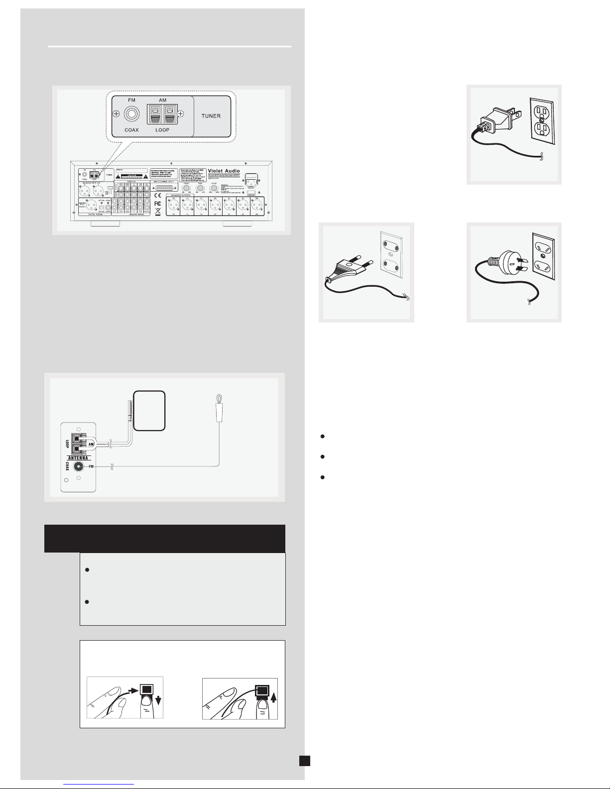
Violet Audio ADP61 User manual

User's Manual V1.3
incorporates software rev.2
ADP61
Violet Audio
Studio AV Preamp Decoder
VOLUME
Violet Audio

1
Voltage:
Voltage are 230/120V AC,50/60Hz.
CAUTION: To reduce the risk of electric shock, do
not remove cover (or back). No user-serviceable
parts inside. Please refer all such issues to
qualified service personnel.
CAUTION
RISK OF SHOCK
NOTICE! !NOTICE! !
Thank you very much for purchasing our product.
pleasure
for many years to come
enjoy
Also, k
We sincerely hope it will bring you much
.
In order to optimum performance from this
unit, as well as for matters of personal safety for all
concerned, please read this manual carefully.
eep it in a safe place for future reference.
Explanation of Graphical Symbols
The lightning flash & arrowhead symbol,
within an equilateral triangle, is intended
to alert you to the presence of danger.
The exclamation point within an equilate-
ral triangle is intended to alert you to the
presence of important operating and ser-
vicing instructions.
Important Safety Instructions
1. Please read all instructions. All the safety and
operating instructions should be read carefully before
operating this appliance.
2. Store these safety and operating instructions in a safe
place for future reference.
3. Please heed all warnings. All warnings issued in this
manual exist not only to prevent potential damage to
equipment, but also to ensure your personal safety.
4. Follow all instructions. In order to enjoy optimum
performance, please follow all instructions and procedures.
5. Do not use this apparatus near water.
6. Remove any dust by using dry cloth or brush.
If more thorough cleaning is necessary, use damp cloth
(in this event, please disconnect unit from AC outlet).
7. Do not block ventilation openings. Proper airflow is
essential for optimum operation.
8. Keep unit away from heat sources such as radiators,
stoves, ovens, heating ducts and devices (including
amplifiers) that can potentially produce heat.
9. Do not tamper with the AC (power) lead. If the plug
provided does not fit your power outlet, consult qualified
service personnel or electrician for a suitable solution.
Also, never use a damaged AC lead, for any purpose!
10. Take measures to protect AC power lead from being
walked on, crushed, twisted, cut or pinched. Exposed
core is highly dangerous if plugged into AC outlet.
11. Only use attachments and accessories as specified
by the manufacturer. Never force connectors!
12. Avoid over-stacking equipment. Stacking more than
two units can become unsafe for equipment and operator
alike. Use only with a cart, stand, mounting brackets or
table specified by your supplier, or specifically sold with
the apparatus. Please secure firmly if using a trolley or cart.
WARNING
To reduce the risk of fire or electric shock, do not
expose this unit to rain or moisture.
PLEASE FOLLOW THESE STEPS:
PLEASE REGISTER YOUR PRODUCT ON
www.violetaudio.com
Continues overleaf

2
Setup and Maintenance of the Receiver
Do not connect to the AC outlet until all other
connections have been completed.
Do not use your receiver immediately after transferring it
from a cold environment to warm. This action may result
in a build up of condensation inside the unit.
Do not expose your receiver to water or excessively high
temperatures.
After having disconnected your receiver, clean the case
with a soft cloth, or with a slightly damp leather chamois.
Never use strong solvents.
Should connectors show build up of contaminants
over a period of time, in order to ensure optimum
performance, clean contacts with appropriate
cleaning agents. Consult your dealer or qualified
service personnel
Protect Your Receiver From Overheating
Do not block ventilation holes
.
any or cover unit with
materials that impede air flow, such as other equipment,
cartons and fabrics etc
Arrange receiver so that air can circulate freely.the
If stacking is absolutely necessary, please allow for
proper air flow between units.
If mounting on a stand or into a 19” EIU equipment rack,
please provide adequate ventilation and spacing with
adjacent units.
Place high heat emitting devices such as
power-amplifiers and satellite receivers away
from receiver and other sensitive components.
To prevent overheating, please provide
sufficient ventilation.
15. Cleaning - Unplug this unit from the wall outlet before cle-
aning. Do not apply spray, aerosols or liquid cleaners directly
onto chassis. If necessary, use only a slightly damp cloth.
16. External antenna - if used with an external antenna, take
care to locate the antenna away from power lines.
17. Accidental object and liquid entry - Care should be taken
so as to prevent foreign objects or liquids entering the enclosure.
Should this occur, detach power cord immediately and refer
unit to qualified service personnel. Do not attempt to power up
again until approved by said personnel.
18. If you have any doubts as to the safe operation or optimum
performance of this unit, please consult your retailer or
qualified service personnel.
13. Unplug receiver during lightning storms or if unused
for long periods of time.
14. All servicing issues should be referred on to qualified
personnel, especially should the apparatus not operate
in a normal manner. It is also highly recommended should
the unit be exposed to rain or be subjected to liquid spills,
objects falling inside or suffer physical damage to chassis,
power-supply cord or plug.
Important Safety Instructions

Table of Content
3
Features 4
Fittings
Installing batteries in the remote controller
Notes About the Remote Control
Remote control operation range
Connecting to Audio-Visual Components
Digital Connections
Connecting the Antenna
AM Loop Antenna and FM Indoor Antenna
Connecting for Power
Connecting Power Amplifiers
or Powered Speakers
Positioning your speakers
Preferred surround placement
Alternative Surround Placement
5
6
6
6
7
8
9
9
9
10
11
12
12
Getting Started ADP61 5
Operating Your ADP61
Panel introduction
The Remote Control
Remote Control Functions
Rear Panel Introduction
Display
Default Window Display Information
Power on / off / standby
Last State Memory
Tone Adjustment
Output Level Adjustment
Speaker
Sleep Function
Display Brightness Adjustment
Tuner Memory Operation
Retrieving Preset Stations
25-pin D-SUB Input
Speaker Settings (Speaker Mode)
Level Calibration
Input Source Selection
Input Source Reference Level Adjustment
Synchro Audio/Video Sources
Audio Format Recognition
Listen Mode Display
Tuner Functions
11
13
14
15
17
17
18
18
18
19
22
24
25
25
25
26
26
26
26
27
28
29
29
11
2 Stereo
6 Stereo
Dolby Pro Logic II Movie
Dolby Pro Logic II Music
Dolby Digital
Dolby Digital SurroundEX
DTS
DTS 96/24
DTS-ES Discrete
DTS-ES Matrix
Neo:6
30
30
30
30
30
30
31
31
31
31
31
About the Listening Modes 30
Sound Enhancement Systems 32
32
32
32
33
33
33
33
Dolby Pro Logic
Dolby Digital and Dolby Digital Surround EX
2/6 Channel Stereo
DSP(Digital Sound Field Processor)
DTS Neo:6
DTS/DTS ES
DTS 96/24
Adjusting the DTS,Dolby Digital LFE Level
Dynamic Range(Night Mode)
Adjusting the Delay Time
Adjusting the Parameter Settings for Pro
logic II MUSIC
34
34
35
35
Advanced Sound Control 30
36
39
39
Troubleshooting 36
General
Tuner
Remote Control
40
40
40
Other 40
Resetting Factory Presets
Abbreviation of the monitor and full
working name
Available Selection All Listening Modes
41
Specifications
Table of Content 3

Digital Sound-field Processing multi-mode
Other Features
Main Features:
4
Dolby Digital Decoder
DTS Decoder
Dolby Digital Surround EX Decoder
DTS 96/24 Decoder
DTS ES Discrete Decoder
DTS-ES Matrix Decoder
DTS Neo:6 Cinema
DTS Neo:6 Music
Dolby Pro Logic II Movie
Dolby Pro Logic II Music
6 CH Stereo Mode
2 CH Stereo Bypass Mode
8 DSP modes: Live, Cinema, Disco, Stadium, Jazz,
Church, Hall & Pro Logic
Manufactured under license from Dolby Laboratories.
"Dolby", Pro Logic", "Surround EX" and the double-D symbol
are trademarks of Dolby Laboratories.
DTS, and DTS ES ,Neo:6 and DTS 96/24 are
trademarks of Digital Theater Systems, Inc.
Up to 24-bit/192khz playback via digital inputs
High-resolution D/A converters
DSP effects, including surround (see DSP modes above)
Operation from front panel or IR remote control
Adjustable sub woofer x-over frequency
Adjustable Reference Volume for each input section (0-15db)
Enhanced Audio Features
Automatic Audio Format Recognition
Source Format Display
Bass Management system, Full Digital
Level individual
Pink Noise Generator for line and speaker test
Treble & Bass
Digital AM/FM tuner
64 Auto Memory Presets (AM/FM separate)
Quartz PLL Synthesized Digital Tuning system
Manual Tuning
Sleep Timer
, DSP
Fully functional remote control
Remote control standby
balanced XLR outputs
7 individual output level and on/off controls
1 analog stereo line output (pre volume-control)
1 digital coaxial input
1 AES/EBU input via XLR
4 S-video inputs, 1 S-video output
4 composite video inputs
1 composite video out
Sub-woofer x-over trim pot (50hz - 150hz)
Adjustable Reference for each
input section (0db to -15db)
trim pots (for FL & FR channels only)
Last State Memory, including routing and decode settings
7
2 XLR balanced inputs with pad switch (+4db, 0db & -10db)
1 digital optical input via TosLink
25-pin D-sub input connector (6-channels +4db bal.)

5
Getting Started ADP61
You should receive the following items:
Fittings
One instruction manual
Indoor FM antenna
AM loop antenna
2 x 19” EIU Rack Adaptors
One ADP61 unit One Remote Control
AAA,R3P,UM-4 batteries
Warranty Information:
Please fill online warranty card
on www.violetaudio.com
AAA,R3P,UM-4 batteries
VOLUME
User's Manual V1.2
ADP61
Violet Audio
Studio AV Preamp Decoder
User's Manual
VOLUME

Notes About the Remote Control
Should you find the remote controls response gradually
decreasing in range, the batteries are most probably reaching
the end of their life. Replace both batteries with new ones,
preferably of matching brand and type.
Remote Control Operation Range
The area between the remote control and the main unit must be
clear of large obstacles.
Do not expose the remote control sensor to strong lighting,in
particular an inverter type fluorescent lamp.Otherwise,the
remote control may not work properly. If necessary, position the
main unit away from direct lighting.
¡30
30¡
Within approximately
6m(19.7feet)
6
Battery Replacement
Notes
Notes
Since the remote control will be used for many of this unit's
control operations, you should begin by installing the supplied
batteries.
1.Turn the remote control over and slide the battery compartm-
ent cover in the direction of the arrow.
2. Insert the batteries(AAA,R03P,UM-4 TYPE) according to the
polarity markings on the inside of the battery compartment.
3.Close the battery compartment cover.
Use AAA,R3P,UM-4 batteries.
Be sure the batteries are correctly oriented according to polarity.
(See the illustration inside the battery compartment.)
Remove the batteries if the remote control is not used for an
extended period of time.
Should any battery leak, dispose of it immediately.
Avoid physical contact of leaked material with skin or clothing
etc. Clean compartment thoroughly before installing new
batteries. If in doubt, consult your dealer or service personnel.
Never dispose of batteries in a furnace or open fire.
Exposure to extreme heat or fire may result in an explosion
and cause possible injury!
Installing batteries in the remote controller
VOLUME
Getting Started ADP61

AC INLET
240V~50Hz 30W TIA 250V
7
Connecting to Audio-Visual Components
If you have a LD player, DVD player or CD player with a digital output, you can make use of an
optical digital cable (not supplied) or coaxial digital cable (not supplied) to carry the audio portion
of the signal and enjoy Dolby Digital sound quality.
One optical or coaxial cable is needed for each LD player, DVD player or CD player. This
receiver provides one optical, one coaxial and one XLR digital input for the connection of your
components. Please connect your components (e.g. LD, DVD, or CD) to the appropriate digital
inputs and press INPUT button to select your connection.
Note:
Optical and coax cables carry only the audio portion of the signal. A separate video connection
must also be established for a LD player and DVD player. S-video provides the best connection
for the video portion of the signal. Composite video (yellow RCA connector) can also be used. It is
important to use the same connection type (S-video or composite) to connect the LD or DVD
player to the ADP-61 and then from the ADP-61 to the TV, LCD or Plasma display.
199
Connect components
capable of outputting Dolby
Digital (e.g. DVD or LD) or
standard PCM(CD) format
digital signals. Read section
on "Digital Connections"
under "Getting Started".
CD Player
Digital Workstation
Tape Deck
VCR
DVD
LD
TV
AUDIO OUT Balanced
To AUDIO OUT (DVD)
To VIDEO OUT (DVD)
To S-VIDEO OUT (DVD)
To VIDEO OUT (VIDEO)
To AUDIO OUT(VIDEO)
To S-VIDEO OUT (VIDEO)
To AUDIO OUT(VCR)
To VIDEO OUT (VCR)
To S-VIDEO OUT (VCR)
To VIDEO IN (TV)
To AUDIO OUT (TV)
To S-VIDEO IN (TV)
Unit
Rear Panel
If your CD or DVD player is equipped with digital output jacks, you can enjoy superior sound quality
by making use of them.
S/PDIF Digital connections are possible via either a TOSLINK optical or a 75ohm co-axial cable with
RCA connectors. For a AES/EBU connection, a 105ohm digital XLR cable is required.
Once connected, simply select either Coax-1, Coax-2 or OPTICAL input for each connection.
Note: This receiver only has one of each digital input type. Yo u may have to use the optical for one unit,
while using the co-axial connection for another.
Also note: Digital cable quality will affect performance. To minimize jitter and other artifacts, only use
good quality, well shielded digital cables.
If your video component has a S-Video output connection,
you can enjoy enhanced video quality by connecting it to
one of the S-Video input sockets on the rear panel of the
ADP-61.
One video cable is needed for each component.
Note: Before plugging in any optical or S-Video cable, make
sure the shape or pin configuration of the plug and socket
match. Be careful not to apply excessive force when making
a connection!
25-pin D-Sub connection for 6 analog channels
i.e. Digidesign, Tascam, Mackie etc.
(+4db balanced) For details see p.29
menu menu
Getting Started ADP61
Multi-form at player/
Extern al decoder
DIGITAL AUDIO
WORKSTATION MIXING CONSOLE

Digital Connections
8
The corresponding video and
s-video input jack is: “DVD”.
The corresponding video and
s-video input is: “VIDEO”.
The corresponding video and
s-video input jack is: “TV”.
HINT
When hooking up an A/V unit, such as a VCR, make sure
to connect to all necessary terminals to the same name,
i.e. S-video or composite video as well as the 2xRCA analog
to all relevant sockets labelled “VCR”. The digital terminals also
correlate with certain video sockets (see HINT in next column)
Be sure to attach the dust covers when the OPTICAL terminals
are not being used. This prevents contamination by dust etc.
For accurate DTS-decoding, the DTS bitstream integrity must
never become compromised. Incorrect or poor quality cables
and connectors can corrupt the bitstream and degrade
performance.
In order to prevent digital errors and enjoy optimal
performance, please use dedicated, good quality digital
cables.
For S/PDIF: 70ohm digital co-axial or TosLink optical.
For AES/EBU: 110ohm balanced digital co-axial cable.
All digital audio signal input terminals accept the following
sample rate frequencies: 32 kHz, 44.1kHz, 48kHz, 96kHz
& 192kHz.
Quality of digital cables and connectors do have a bearing
on sound quality and performance. Keep cable lengths to
a minimum.
If your CD, LD, DVD, TV/satellite tuner or DAW etc, are
equipped with a either coaxial, optical or AES/EBU XLR
digital output terminals, you can take advantage of this
sonically superior connectivity by utilizing the corresponding
input sockets on the ADP61's rear panel
Digital audio signals are not prone to the same type of signal
loss and distortion factors as observed with typical analog
connections. Digital connections are especially recommended
when decoding multi-channel surround information, such as
Dolby Digital and DTS from LD, DVD, CD players, and
other digital sources.
To make an optical digital connection between this unit and an
external unit, remove the cover from each optical terminal, and
then connect them by using a commercially available optical
fiber cable that conforms to EIAJ standards.Other cables might
not function correctly.
Even if you connect an audio/video unit to the OPTICAL (or
COAXIAL) terminal of this unit, you must keep the unit connec-
ted with the same named analog audio signal terminals of this
unit, because digital signal cannot be recorded by a tape deck
or VCR connected to this unit. You can switch the selection of
input signals between digital and analog easily.
DVD
CD
COAXIAL OUT
OPTICAL OUT
S-VIDEO OUT
VIDEO OUT
Notes
Getting Started ADP61

AM Loop Antenna and FM Indoor Antenna
1.
2.
Uncoil the Antenna wire.
Press down on the Antenna tab to open the terminal.
Connecting the Antenna
The AM and FM antennae connect to the top left section
of the rear panel of the ADP-61.
They must be hooked up in order to receive clear reception.
HINT
For best FM reception, extend antenna to its
full length and position at highest possible
elevation.
For AM, rotate the antenna horizontally
for optimum reception.
1. 2.
AM Antenna
wire Connection
Connecting for Power
Make sure you connect up all your
other electronic components and
the speakers before plugging your
receiver into the outlet. Plug the
power cord in the wall outlet,
matching the wide blades of the
plug with the wide slots of the outlet.
Be sure to insert the plug
completely.
Notes:
Do not play audio at a high volume. Hearing experts
advise against continuous extended play.
If you experience a ringing in your ears, reduce volume or
discontinue use.
Always turn down the volume before connecting your speakers
.
9
Getting Started ADP61
AC INLET
240V~50Hz 30W TIA 250V US power plug
European power plug Australian power plug

AC IN L ET
240V~50Hz 30W TIA 250V
10
SUB WOOFER
SURROUND RIGHT
SPEAKER
FRONT CENTER
SPEAKER
FRONT RIGHT
SPEAKER
RIGHT
LEFT
RIGHT
LEFT
SURROUND CENTRE
SPEAKER
Connecting Power Amplifiers.
If you are using Powered Speakers, simply connect directly to ADP61 corresponding XLR outputs
SURROUND LEFT
SPEAKER
FRONT LEFT
SPEAKER
POWER
0
1
2
3
56
7
8
9
10
4
0
1
2
3
56
7
8
9
10
4
Professional Power Amplifier
Dc&Tem p
Clip
Sign al
Powe r(Br idge ) POWER
0
1
2
3
56
7
8
9
10
4
0
1
2
3
56
7
8
9
10
4
Professional Power Amplifier
Dc&Tem p
Clip
Sign al
Powe r(Br idge ) POWER
0
1
2
3
56
7
8
9
10
4
0
1
2
3
56
7
8
9
10
4
Professional Power Amplifier
Dc&Tem p
Clip
Sign al
Powe r(Br idge )
POWER
0
1
2
3
56
7
8
9
10
4
0
1
2
3
56
7
8
9
10
4
Professional Power Amplifier
Dc&Tem p
Clip
Sign al
Powe r(Br idge )
Getting Started ADP61

12
39
45710
12 13 14 15 16 17 20
11
8
6
18 19
Operating Your ADP61
Panel Introduction
11

12
Surround, Center, Subwoofer.
Clockwise rotation increases volume, while anti-clockwise
reduces it.
POWER switch
Press this switch to turn on the power. Press the switch again
to turn off. Note: Power ON defaults to Standby mode.
13. TEST
Sends Pink Noise test tone sequentially to each analog output.
This enables you to balance output channel levels as well as test
your amplifier and speaker connections.
Also performs Reset function. See page 40 "Resetting Factory
Presets".
14.Dolby Digital & Dolby Digital Surround EX mode
Note:
15.
16.
Note: Input sources must be DTS or DTS ES
17. 2/6 STEREO
Selects playback of standard 2-channel stereo mode
(BYPASS) or splits signal into 6 channels (3 x stereo)
18.
19. A/B/C/D
Selects one of the 4 preset station groups (A to D) when the
unit is in tuner mode.
20.
12.
-encoded.
selection button.
DTS Neo:6 Cinema/Music mode selection button
DTS & DTS ES mode selection button.
PROLOGIC II.
Select between Cinema and Music mode for surround
enhancement of stereo source or decoding of Dolby
encoded video tape or LD.
Number 1-8 button
Press these buttons to select preset tuning channel.
Operating Your ADP61
Input sources must be Dolby Digital or Dolby Digital Surround
EX-encoded.
1.ADJUST
This control enables you to adjust individual parameter values,
with the exception of the master volume.
.
4INPUT selector
Enables the selection of
LISTEN MODE
Enables the selection of preferred output modes
7.
Live, Cinema, Disco, Stadium, Jazz, Church,
Hall and ProLogic.
8.
Note:
Default parameter is REF (Reference Level for currently
selected input).
2.Standby indicator
Lights up when unit is in standby mode.
3MENU selector button
Press the button repeatedly to scroll through the parameter
MENU of the current output mode. Use the "ADJUST " knob
to edit parameter value.
.
input sources.
5.
.
Note:
Dolby Digital and DTS modes only available when receiving
from external digital source. I.e. DVD player etc.
6. Display window
Displays a variety of information. e.g. Volume levels, DSP,
currently active input source, listening mode and individual
parameter values etc.
DSP mode
Selects between eight artificial acoustic surround
environments:
FM/AM
Selects either the FM or AM radio bands.
9.Remote control sensor
Receives signals from the remote control.
10.TUNER AUTO automatic radio tuning button
Hold down the button for more than 3 seconds to start automa-
tic preset tuning (AM/FM have separate memory banks).
11.Master VOLUME control
Simultaneously controls volume for all output sounds; Front,

VOLUME
Operating Your
ADP61
Your Remote Control
Please be sure you have inserted the batteries into the remote
control.
13
1
4
5
6
7
8
9
10
11
12
13
14
15
16
17
18
1
2
3

Operating Your
ADP61
Remote Control Function
1. I selector section
2.
3. Numerical keypad (from 1-8)
Press these buttons to select preset tuning channel.
4. Tuning scan buttons
5.
6. TEST
Activates Pink Noise test tones to each output sequentially.
7. S
8. DTS & DTS ES mode selection button
9.DTS Neo:6 Cinema/Music mode selection button
10. POWER
Alternates between Power On and Standby Mode.
For this button to function, first make sure the POWER
switch is depressed on the ADP-61’s main panel and
that the red standby light is on.
11.A/B/C/D
nput
Selects the input source you want to listen to or watch.
TUNER automatically tuning button
Hold down the button for more than 3 seconds to start automa-
tic preset tuning (AM/FM is detached).
Press the SCAN+ side to tune in to a higher Frequency.
Press the SCAN- side to tune in to a lower frequency. Press
and hold for two seconds to scan automatically.
Master volume
ET MAIN MENU button
Press these buttons to turn the unit into the SET MAIN
MENU mode.
Scroll to the desired parameter by using the L or R buttons,
then press the + or - buttons to adjust value.
Note:
Input sources must be DTS or DTS ES
Controls the level of all seven XLR output channels.
-encoded.
Selects one of the 4 preset station groups (A to D), when
the unit is in tuner mode.
12. Stores a station in the memory
13. MUTE
Mutes the sound. Press again to restore the audio out to the
previous volume level.
14. DSP mode selection button
Eight DSP modes: Live, Cinema, Disco, Stadium, Jazz,
Church, Hall, and ProLogic.
15. Dolby Digital & Dolby Digital Surround EX mode
selection button
Note:
16. 2 channels stereo mode & 6 channels stereo
mode selection button
17. Dolby Pro logic II Movie/Music mode selection
button
18. SLEEP button
Sets the sleep time:10min,20min,30min,40min, 50min,60min,
70min,80min,90min,100min,110min,120min.
Input sources must be Dolby digital or Dolby Digital Surround
EX-encoded.
14

AC INLET
240V~50Hz 30W TIA 250V
Rear Panel Introduction (note.. Current model has Treble and Bass Control on the rear Panel)
15
Operating Your
ADP61
1 2 3 4 5 6 7 8 9 10
11 1312 14 1918171615 21 22 23 24 25 26 27
28 29 30 20

Operating Your
ADP61
1.CD or DAW Balanced input jacks
2..FM antenna input
3.AM antenna input
4.CD input gain switch
5.Video input jacks
Note: using corresponding analog audio jack.
6.S-Video input jacks
Note: using corresponding analog audio jack.
7.S-Video output jack
8.Video output jack
9.25-pin D-sub balanced 6-channel input
10.AC ~220/240V 50/60Hz power input plug
11.Digital AES/EBU. XLR input jack
12.Digital coaxial input jack
Note:
13.Digital optical input jack
Note:
14.AUX Analog Audio input jacks
15.DVD Analog Audio input jacks
16.VIDEO Analog Audio input jacks
17.TV Analog Audio input jacks
18.VCR Analog Audio input jacks
19.PRE Analog Audio output jacks
20.Voltage:AC 230V 50/60Hz
AC 115V 50/60Hz
21.Front Right Balanced output
22..Front Left Balanced output
23.Front Center Balanced output
24.Surround Right Balanced output
25.Surround Left Balanced output
26.Surround Center Balanced output
27.Subwoofer Balanced output
28. TREBLE control
Affects only Front Left and Front Right outputs
29. BASS control
Affects only Front Left and Front Right outputs
30. LSF SET
Adjusts the low-pass frequency point for the
sub-woofer channel. Adjustable from 50Hz to 150Hz
Corresponds with the DVD input socket group,
including Composite Video and S-Video.
Note:
Corresponds with the TV input socket group,
including Composite Video and S-Video.
Corresponds with the VIDEO input socket group,
including Composite Video and S-Video.
16

Operating Your ADP61
Display
1.DOLBY DIGITAL/DIGITAL.EX/PRO LOGIC II
Lights up when a Dolby Digital signal is received.
Lights up when a Dolby Digital EX signal is received.
Lights up when Dolby Pro logic II mode is selected.
2.DTS DIGITAL SURROUND
Lights up when a DTS signal is received.
3.DTS ES
Lights up when a DTS ES signal is received.
4.DSP
Lights up when DSP mode has been activated.
5.
Blinks to show that a station can be stored.
6.STEREO
lights up when a sufficiently strong FM
stereo broadcast signal is received.
7.TUNED
Lights up to indicate correct tuning to a station.
8.INPUT SOURCE INDICATOR
MEMORY
Shows which input source is currently active.
TUNED
CD
AUX
TUNER
VIDEO
TV
VCR
DVD 6CH
MEMORY
1 2 3 4 5 6 87
9
9. Speaker Configuration Indicator
Shows all currently active speaker outputs.
FL:Front Left channel
FC:Front Center channel
FR:Front Right channel
LFE:Subwoofer channel
SL:Surround left channel
SC:Surround center channel
SR:Surround right channel
MUTE: Blinks when the MUTE function is on.
17
TUNED
AUX
TAPE
TUNER
VIDEO
TV
VCR
DVD 6CH
MEMORY
Default window display information (software rev.2 only)
1. Current output configuration
2. Currently selected input source
3. Input source Reference Level
4. Master Volume setting
5 Additional input selection options
During typical operation, once a function has been selected
or a parameter value changed, the display window will
automatically revert to this default display mode after 5 seconds.
1. 2. 3. 4. 5.

Switching On / Off
Operating Your ADP61
In order to get started, we need to be in Standby mode. For
this to happen, make sure the POWER switch on the panel is
pressed in. A red indicator light will confirm Standby mode on
the display panel.
Now, either press any of the 16 buttons on the front panel of
the ADP61 or the STANDBY button on the remote control.
You should now see the message VIOLET AUDIO scroll by.
To go return to STANDBY mode: simply press the STANDBY
button on the bottom left of the remote control.
NOTES:
1. Standby mode can only be activated by remote control.
The ADP-61 features a Last State Memory function.
This means that when powering up, all selections and
settings from the previous session will be restored.
The exception being volume settings above 40db
POWER DOWN: To turn unit off completely, simply press
the POWER switch on unit front panel. This will also
defeat the Standby mode. Unit can only then be
powered up again by first depressing the POWER switch
on the front panel.
2. Standby mode consumes a small amount of power in
order to receive power ON command from infrared
remote control.
Front Panel
Remote Control
TUNED
TUNED
AUX
AUX
TAPE
TAPE
TUNER
TUNER
VIDEO
VIDEO
TV
TV
VCR
VCR
DVD
DVD
6CH
6CH
MEMORY
MEMORY
To Adjust the Tone
Basic equalisation control. Affects only Front Left & Right
output channels
Turn the TREBLE knob on the panel to adjust high-frequency
level. The indented middle position denotes a flat curve, or 0db
boost/cut.
Turn the BASS knob on the panel to adjust high-frequency
level. The indented middle position denotes a flat curve, or 0db
boost/cut.
Adjust Low-frequency Level
Adjust High-frequency level
Rear Panel
18
MENU
TEST
Rear Panel
Rear Panel
Subwoofer frequency
Set the desired low-pass frequency threshold with the LSF SET
knob. Range: 60~150Hz. (Lucasfilm THX specification is 80Hz).
The next state will display similar to this:
For more information, see p.17
(Default Window Display Information)
Last State Memory

Operating Your ADP61
Front Panel
Remote Control
TUNED
CD
AUX
TUNER
VIDEO
TV
VCR
DVD 6CH
MEMORY
SMALL:Select this position if your front center speaker is sma-
ller than the main speakers. In this position, low bass signals
(100 Hz)at the front center channels are output from the subw-
oofer speaker,or output from left and right main speaker if the
subwoofer speaker is in "N" position.
3.Surround Left and Right Speakers
Use the panel
on the remote to select "S SPEAK ", and turn the
ADJUST knob on the panel or u or
buttons on the remote select position.
Choices:LARGE,SMALL,NONE.
LARGE:Select this position if you have large surround left and
right speakers or if a surrround subwoofer i
front center
surround left and right speakers.
left and right
left and
right
NONE:S
left and right left and
right
MENU button on the or the Left and Right or
buttons
se the Up and Down
to
Initial setting:LARGE.
s connected to your
surround speakers.The entire range of the signal is
directed to the
SMALL:Select this position if your surround spe-
akers do not have a high ability for bas reproduction. In this
position, low bass signals (100 Hz) at the surround
channels are output from the subwoofer speaker , or
output from left and right main speaker if subwoofer speaker
is in "N" position.
elect this position if your system does not include the
surround speakers. All of the surround
channel signals are directed to the main speakers.
Speaker Setting(Speaker Mode Settings)
Use this feature to select suitable output modes for your spea-
ker configuration.
Front Panel
Remote Control
DSP
1.Main Speakers
2.Front Center Speaker
TUNED
CD
AUX
TUNER
VIDEO
TV
VCR
DVD 6CH
MEMORY
Use the panel
on the remote to select "M SPEAK ",and turn the
ADJUST knob on the panel or u or
buttons on the remote select position.
Choices:LARGE,SMALL.
LARGE:
MENU button on the or the Left and Right
or buttons
se the Up and Down
to
Initial setting:LARGE.
If your main speakers have a high ability for bass
reproduction. In this position, full range signals present at the
main channels are output from the main speakers.
SMALL: If your main speakers do not have a high ability for
bass reproduction. However, if your system dies not include a
subwoofe,do not select this position.In this position,low bass
signals are output from the subwoofer speaker(100Hz).
Use the panel
on the remote to select "FC SPEAK ",and turn the
ADJUST knob on the panel or u or
buttons on the remote select position.
Choices:LARGE,SMALL,NONE.
LARGE:Select this if the front center speaker i
front center front center speaker
MENU button on the or the Left and Right or
buttons
se the Up and Down
to
Initial setting:LARGE.
s approximately
the same size as the main speakers. The entire range of the
signal is directed to the .
19
NONE:
Select this position if your system does not include a front center
speaker. All of the front center channel signal are directed to the
main speakers.
MENU
TEST
MENU
TEST
DSP
Other manuals for ADP61
1
Other Violet Audio Media Converter manuals