Violet Defense Vantage I Guide
USER MANUAL & WARRANTY
Vantage I
Vantage II
Violet Defense, LLC | www.violetdefense.com | +1.407.433.1104
© Copyright 2021 Violet Defense, LLC All Rights Reserved VNTG-USRMNL-2021
®

SAFETY WARNINGS 1
DIRECTIONS FOR USE 4
STANDARD UNITS - OPERATIONAL GUIDELINES 5
BUILDING AUTOMATION ENABLED UNITS -
OPERATIONAL GUIDELINES 6
RECOMMENDED CLEANING PROTOCOLS 11
TROUBLESHOOTING 12
INSTALLATION 13
UV GOVERNMENT GUIDELINES 16
TABLE OF CONTENTS

1
© Copyright 2021 Violet Defense, LLC All Rights Reserved VNTG-USRMNL-2021
SAFETY WARNINGS
IMPORTANT SAFEGUARDS
Given the correct combination of user protocols and the built-in safety features, there are
minimal risks of any harmful eects from using the Vantage UV units.
RECOMMENDATIONS
• If in the vicinity of the Vantage UV unit during operation, do not look directly at the light.
This is similar to how one would avoid harmful eects from the sun by not looking directly
at it.
• Germicidal UV light does not signicantly penetrate standard glass.
• Per the built-in safety features described below, the unit is designed to not operate while
a room is occupied. However, operators are instructed to have all persons vacate a space
before operation. Signage indicating that persons should use caution as the UV unit may
be in operation are also recommended.
SAFETY FEATURES
The Vantage UV units have four primary aspects to their built-in safety features to ensure the
safety of anyone operating the unit or in its vicinity.
Limited Exposure Risk
Due to the nature of the programming on the Vantage UV units, over a 30-minute cycle time for
the unit, the actual exposure to UV (if there were no other safety systems in place) would be no
more than two seconds of exposure.
Motion Detection
Each Vantage UV unit has built-in passive infrared (PIR) sensor used to detect motion in a space.
The sensor is programmed to detect individuals walking into the deployment space. The unit will
not resume operation of the cleaning cycle until it has successfully detected the space is free of
motion.
Safe Stop
The third layer of protection built into the Vantage units is to ensure that if the motion sensor
or other components experience technical issues, the unit will safe stop by cycling the unit o.
The unit will ash red indicating that one should contact Violet Defense for technical support.
The unit will not resume operation until the issue detected has been resolved. If unit is non-
responsive (i.e. non-operational or no indicator light), contact Violet Defense.
Frequency of Flashes
The Vantage UV units will ash every 6 seconds during operation. Violet Defense collaborated
with the Epilepsy Foundation when designing the product to ensure that the frequency of ashes
will not cause any issues for someone with photosensitive epilepsy.

READ AND FOLLOW ALL SAFETY INSTRUCTIONS
1. Read these instructions prior to operating the unit. For the most up-to-date manual, visit www.
violetdefense.com/resources.
2. Heed all warnings. Failure to use the equipment in the manner specied may impair the unit from
providing the desired protection.
3. THIS EQUIPMENT IS DESIGNED FOR USE WITH GERMICIDAL LAMPS OR UV SOURCES. STRICT
ADHERENCE TO THE INSTALLATION DIRECTIONS IS NECESSARY TO PREVENT OCCUPANT
EYE AND SKIN EXPOSURE TO HARMFUL RADIATION.
4. This equipment is designed for use with germicidal UV radiation sources and must be installed
in compliance with competent technical directions to prevent risk of personal injury from UV
radiation.
5. UV radiation can pose a risk of personal injury. Overexposure can result in damage to eyes and
bare skin. To reduce the risk of overexposure this equipment must be installed in accordance with
the manufacturer’s site planning recommendations, including instructions on relative location
of each germicidal system component, the minimum distances between UV-generating devices
and other objects or surfaces, and protection from line-of-sight exposure to UV radiation in
unoccupied spaces located above the equipment mounting area (e.g. upper oor balconies, open
staircases, etc.).
6. UV and optical radiation can be reected by surrounding surfaces such as ceilings and walls. Since
reective properties of surfaces can vary widely, it should be considered as part of site planning.
Follow the manufacturer’s recommendations for selecting appropriate ceiling and wall nishes.
7. IT IS THE RESPONSIBILITY OF THE INSTALLER TO ENSURE THAT PERSONS WILL NOT BE
EXPOSED TO EXCESSIVE UV OR OPTICAL RADIATION DURING EQUIPMENT OPERATION. THIS
WILL REQUIRE THE INSTALLER TO CONDUCT AN ASSESSMENT OF ALL SITE AND EQUIPMENT
SAFEGUARDS TO ENSURE THE SYSTEM IS OPERATING IN ACCORDANCE WITH THE SYSTEM
MANUFACTURER’S INSTRUCTIONS, INCLUDING AN ASSESSMENT OF IRRADIANCE OR
ILLUMINANCE LEVELS IN THE SURROUNDING OCCUPIED SPACES.
8. Equipment should be mounted in locations and at heights where it will not readily be subjected to
tampering by unauthorized personnel.
9. Equipment contains no user serviceable components. Contact Violet Defense for service.
Maintenance and servicing of this UV generating equipment shall be performed by authorized
personnel. Service personnel must wear appropriate Personal Protective Equipment (PPE) if the
equipment will be in operation during the maintenance or servicing work. Contact the equipment
manufacturer for PPE recommendations and guidance.
10.The use of accessory equipment not recommended by the manufacturer may cause an unsafe
condition.
11.Do not use this equipment for other than intended use.
12.Plug unit into a grounded outlet. Ensure proper conditions for operation. The unit is designed
to operate under normal conditions indoors (temperature 5-40 degrees Celsius, RH less than
80% (non-condensing), at an altitude <2000m and main supply uctuations +/- 10% of nominal
voltage, overvoltage Category II.
13.Allow unit to complete pre-programmed cycles prior to unplugging or shutting o power. This
allows it to enter safe mode.
2

CAUTION: TO REDUCE THE RISK OF ELECTRIC SHOCK, DO NOT
REMOVE COVER. NO USER-SERVICEABLE PARTS INSIDE. REFER
SERVICING TO QUALIFIED SERVICE PERSONNEL.
The lightning ash with arrowhead symbol, within an
equilateral triangle is intended to alert the user to the
presence of uninsulated “dangerous voltage” within
the product’s enclosure that may be of sucient
magnitude to constitute a risk of electric shock to
persons.
WARNING: TO REDUCE THE RISK OF FIRE OR ELECTRIC
SHOCK, DO NOT EXPOSE THIS UNIT TO RAIN OR
MOISTURE.
This device complies with FCC Part 15B Class A, ICES-003 Issue 7 Class A and Directive 2014/30/EU. Operation is subject
to the following two conditions: (1) this device may not cause harmful interference, and (2) this device must accept any
interference received, including interference that may cause undesired operation.
NOTE: This equipment has been tested and found to comply with the limits for a Class A digital device, pursuant to FCC Part
15B, Class A, ICES-003 Issue 7 Class A and Directive 2014/30/EU. These limits are designed to provide reasonable protection
against harmful interference when the equipment is operated in a commercial environment. This equipment generates, uses,
and can radiate radio frequency energy and, if not installed and used in accordance with the instruction manual, may cause
harmful interference to radio communications. Operation of this equipment in a residential area is likely to cause harmful
interference in which case the user will be required to correct the interference at his own expense.
14.Do not allow the unit to get wet or be used in or near water.
15.Do not block any ventilation openings. Use in accordance with these instructions.
16.Do not attempt to open or tamper with the unit.
17.Do not place or store the unit near any ammable materials or liquids.
18.Do not defeat the safety purpose of the polarized or grounding-type plug. A polarized plug has
two blades and a third grounding prong.
19.Protect the power cord from being walked on or pinched particularly at plugs, convenience
receptacles, and the point where they exit from the unit.
20.Unplug this unit during lightning storms or when unused for long periods of time.
21.Refer all servicing to qualied service personnel. Servicing is required when the unit has been
damaged in any way, such as power-supply cord or plug is damaged, liquid has been spilled or
objects have fallen into the unit, the unit has been exposed to rain or moisture, does not operate
normally, or has been dropped.
22.Unit is designed to operate only when the room is unoccupied. There are redundant safety
systems to ensure the unit does not activate while the room is occupied as the UV light is not
recommended for excessive exposure. If the sensor in the system fails, the system will shut down.
23.Do not look directly at the unit due to the brightness of the light. UV light does not signicantly
penetrate standard glass, therefore, incidental exposure on the other side of a window or wall
does not present any signicant risk.
THIS PRODUCT IS NOT A TOY. KEEP AWAY FROM CHILDREN.
SAVE THESE INSTRUCTIONS
3

Disclaimer: The Vantage UV unit is not intended for use as a medical device and people should not be directly exposed to the light generated
by the unit. The actual disinfection rates on a specic space will vary depending on time, distance, pathogens, and product selection.
DIRECTIONS FOR USE
1. The Vantage UV unit is designed to be deployed approximately 2 meters (~6 1/2 feet) away from priority
areas. See page 14 for additional information on installation and other deployment methods. Reective
surfaces, including metallic surfaces, tiles, and safety glass will enhance the eectiveness of the unit as
the UV light will reect o of these surfaces. Do not block or interfere with the PIR motion sensor as this
ensures the unit will only activate when the space is unoccupied.
2. The unit should be either plugged into a proper grounded outlet or hard-wired following appropriate
electrical code per your model. Ensure the breaker is properly sized for operation.
3. While the unit is operational, all personnel should leave the space during the cleaning cycle. Exit the
space within 60 seconds for optimal functioning of the unit. Provided signage should be used to advise
persons in the space to use caution as UV disinfection may be in progress. Additional signage options
available through Violet Defense.
4. The unit’s redundant safety systems will stop the unit from operating if motion is detected in the
space. The unit will resume operation approximately 60 seconds (unless alternate motion timeout was
selected) after room is unoccupied and no additional motion is detected. If any issues are detected with
the unit, turn o power to the unit and contact Violet Defense for support.
5. The unit will run a safety test to ensure unit is functioning properly and that there is no motion detected
in the space. If successful, unit will run its pre-programmed operational cycle. See guidelines for
standard unit or building automation enabled units for more information on operational modes.
6. Allow the unit to complete its entire cycle before unplugging or turning o power to the unit to allow the
unit to enter safe mode. If necessary to cease operation prior to completion of cleaning cycle, be sure to
keep unit away from water for optimal safety. The units should have a 15-minute cool down period after
each 30-minute disinfection cycle.
PRODUCT FEATURES
Uses Pulsed Xenon
technology to deploy
powerful bursts of
UV-C, UV-B, UV-A, and violet-blue light
with ~170⁰ of coverage
Built-in PIR motion sensor will actively
monitor the space and only allow the
unit to activate when the space is
unoccupied
GENERAL OPERATION
© Copyright 2021 Violet Defense, LLC All Rights Reserved VNTG-USRMNL-2021
4
LED Indicator Light to provide
operational status of unit
Model Volts Amps Frequency
VNTG1-31-I
VNTG1-31-LP
100-240VAC 1.6-0.8A 50/60Hz
VNTG1-31-F 100-240VAC
277VAC
1.6-0.8A
0.8A
50/60Hz
60Hz
VNTG2-31-I 100-240VAC 3.0-1.5A 50/60Hz
VNTG2-31-F 100-240VAC
277VAC
3.0-1.5A
1.2A
50/60Hz
60Hz
Vantage I

DIRECTIONS FOR USE
STANDARD UNITS
CONFIGURING THE UNIT
The Vantage Wizard can be used to congure units to the preferred programming mode and adjust
related settings. This conguration should be completed before initial operation or as changes need
to be made. To begin, visit www.violetdefense.com/wizard to download the Vantage Wizard and
computer conguration instructions. After downloading, run the installer and a shortcut will be placed
on computer’s start menu and desktop.
1. Congure your computer per instructions.
2. Plug the Vantage unit into your computer using an Ethernet cable.
3. Open the Vantage Wizard and follow the on-screen instructions to congure the unit, including
operational mode, related settings such as length of motion time-out, runtime for manual or
scheduled mode, and scheduling options, such as start-time for scheduled mode.
4. Once completed, unplug the cable and install the unit. See additional installation instructions on
page 14.
Each standard unit has 3 primary modes available to users. Fixtures must be programmed before
initial use.
• Autonomous Mode: In this mode, once plugged in, the unit will automatically activate
once the space is unoccupied and continue disinfection on a regular schedule, adjusting
frequency based on level of activity in the space based on the motion sensor. Users may
select the timeout time, which determines how long the unit will wait until resuming
operation after motion is detected.
• Scheduled Mode: In this mode, the unit will activate at selected time(s) of day during each
24-hour period. Users may schedule up to 8 start times each day to operate for a specied
run time (i.e. 10,15,20,25 or 30 minutes). Users may select the motion timeout, which
determines how long the unit will wait until resuming operation after motion is detected.
The unit may also be congured to activate a disinfection cycle immediately when it is
powered and then continue with the scheduled operational time(s).
• Single Cycle Mode: In this method, users will manually activate the unit to start a
disinfection cycle. The unit will then run its pre-programmed cycle (i.e. 10,15,20,25 or 30
minutes) one time before entering safe mode until power is cycled on and o again. Users
may select the timeout time, which determines how long the unit will wait until resuming
operation after motion is detected.
OPERATIONAL MODES
STANDARD UNITS
© Copyright 2021 Violet Defense, LLC All Rights Reserved VNTG-USRMNL-2021
5

Building Automation Enabled Vantage units have 5 operating modes available to users that may
be enabled and/or adjusted from your building automation control system (see pages 8-10 for
additional information).
• Manual Mode: User will manually activate the unit to start a disinfection cycle. The unit
will then run its pre-programmed cycle length one time before entering safe mode until
power is cycled on and o again.
• Autonomous Mode: The unit will automatically activate once the space is unoccupied and
continue disinfection on a regular schedule, adjusting frequency based on level of activity
in the space based on the motion sensor.
• BMS Mode: The unit will operate disinfection cycles similar to that of manual mode.
However, the unit will have to be activated from within your building automation system
software. For safety, UV light should only be deployed in unoccupied spaces. Please
ensure that you either activate the safety features or have an acceptable alternative
control to prevent occupant exposure to the UV light.
With the building automation capabilities of the Vantage UV Whole Room Unit, users have the ability
to adjust the following:
• Operational Modes & Settings*: Select operating modes, including type of disinfection
cycle and related selections, such as start time, run time, and motion timeout length, which
indicates how long the unit will wait to attempt re-activation after motion has been detected
• System Monitoring: Monitor current status of units remotely and troubleshoot operating
• Network Settings: Congure network settings and/or troubleshoot any networking issues
• Metrics: Access data on the units, including number of successful cleaning cycles and runtime
over specied period of time or lifetime of unit
BUILDING AUTOMATION ENABLED UNITS
BUILDING AUTOMATION UNITS
© Copyright 2021 Violet Defense, LLC All Rights Reserved VNTG-USRMNL-2021
6
*Modes and conguration options are subject to change. Visit www.violetdefense.com/resources for
current user manual or contact the team at Violet Defense with any questions.

BUILDING AUTOMATION UNITS
© Copyright 2021 Violet Defense, LLC All Rights Reserved VNTG-USRMNL-2021
7
GETTING STARTED
To get connected to your Vantage unit, use one of the following two methods:
Connect Automatically Using a DHCP-enabled Router
1. Connect one end of an Ethernet network cable to the Vantage unit, and the other into
a DHCP-enabled router. Ensure your computer is connected to the same router (either
Ethernet or Wi-Fi).
2. Ensure your Vantage unit is powered on.
3. Use your BACnet software of choice to discover the Vantage device.
Connect manually using a direct Ethernet connection
1. Connect one end of an Ethernet network cable to the Vantage unit, and the other directly
into your computer’s Ethernet adapter.
2. Ensure your Vantage unit is powered on.
3. On your computer, set your connected Ethernet adapter’s IP address to “192.168.1.2”
4. Use your BACnet software of choice to discover the SAGE device. By default, the SAGE
device will bind to address “192.168.1.5” (Note: It may take up to 15 seconds for the device
to appear on network after bootup.)
Network Troubleshooting
1. If your BACnet software is having trouble discovering the device, try an alternate connection
method. Verify each step carefully. If it is still not responding, try rebooting the unit or using
the reset pinhole located next to the unit power source to restore the default memories.
2. The unit’s network conguration can be reset to factory default by holding the reset button
in for at least 2 seconds and then releasing. This will clear all congured IP settings and reset
the unit to preferring a DHCP-assigned IP address, but will fall back to a known address
(192.168.1.5) if no DHCP-router is detected (in the case of a direct connection, for example).
3. The unit’s entire congurable memory can be factory reset by holding the reset button in for
at least 10 seconds and then releasing. This will put the unit into manufacturing mode until
congured otherwise. In this mode, the unit can only be manually connected to (method 2)
until the 5-ash cycle has nished. When the LED is solid green, reboot the unit, and then
automatic connection (method 1) will be possible.
4. Note: If a user congured BACnet object “DHCP CNFG” to disabled, automatic connection
(method 1) will be impossible. Holding the reset button in for 2 seconds will recover this state.
5. Note: If a user congured BACnet objects “IP Address CNFG”, “Subnet Mask CNFG”, or
“Gateway CNFG”, both automatic and manual connections may be impossible. Holding the
reset button in for 2 seconds will recover this state.

BUILDING AUTOMATION UNITS
© Copyright 2021 Violet Defense, LLC All Rights Reserved VNTG-USRMNL-2021
8
BACnet Variable Description Options
Real-Time Clean STS Indication of unit’s cleaning cycle status 1= Unit nished a cleaning cycle
0 = Unit has not yet completed its
current cleaning cycle
Motion Detected STS Indication of status of PIR sensor 1 = Unit has detected motion
0 = No motion detected
UV Cleaning STS Indication of unit’s current operational status 1 = Unit is running/cleaning
0 = Unit is not cleaning
Time Until Clean Remaining time (in seconds) until the unit is nished its
current cleaning cycle
Self Test STS Reports any issues with the unit that can be detected
by on-board diagnostics
RTC Device Time STS Displays the time currently stored on the device. Note:
Read-only. Time must be synchronized using your
BACnet client’s time sync function.
(Year-Month-Day)
(24-Hour:Minute:Second)
SYSTEM MONITORING
OPERATIONAL MODES & SETTINGS
BACnet Variable Description Options
Operating Mode CMD Set operating mode for the unit. See descriptions on
page 5.
Manual; Autonomous; BMS
Cleaning Internal Runtime
STPT
Set the amount of time (in minutes) the unit cleans for in
manual mode.
Range 1 minutes to 30 minutes
Motion Timeout STPT Sets the number of seconds for which the unit will pause
when it detects motion.
Range 15 seconds to 1800 sec-
onds
Enable Cleaning CMD Manually turn the unit on/o. 0 = Unit is off
1 = Unit is on
Enable Safeties CMD When safeties are enabled, unit pauses cleaning when
PIR detects motion.*
0 = Safeties are disabled
1 = Safeties are enabled
Cleaning Schedule Unit will start cleaning on any schedules set here.
Synchronization of BACnet time with on-board clock is
recommended. The schedule will repeat each week on
the specied day and time.
Each day supports a maximum of
8 scheduled times.
Reboot Device CNFG Reboots device
RTC Daylight Saving Rule
CNFG
If this eld is blank, automatic daylight saving time
changes are disabled. To enable DST, you must set rules
for the start and end dates using specic grammar.
See “Automatic Daylight Saving
Grammar” section on page 10
RTC Time Zone This user-dened string has no functional impact on
the unit, but is intended to be used as a note describing
which time zone the unit is in.
User-dened time zone string
*Please note that units should only be activated when a space is unoccupied. If safeties are disabled,
user is responsibility fore ensuring an acceptable alternate control method is deployed to avoid any UV
exposure risk.

NETWORK SETTINGS
BACnet Variable Description Options
DHCP CNFG When DHCP is enabled, ethernet settings are acquired
automatically. If the unit fails to acquire a DHCP IP address,
it will default to 192.168.1.5. When disabled, enter your
custom settings via the IP Address, Subnet Mask, and
Gateway Objects. Then reboot the device to apply network
changes.
Enabled/Disabled
Factory Default IP CNFG Sets all network settings back to their factory defaults.
Sets the MSTP baud rate back to the default (38400) and
the MSTP MAC address to the default (55).
MSTP Baud Rate CNFG Use this to set the MSTP baud rate. Supported device baud rates:
9600; 19200; 38400; 57600;
76800; 115200
IP Address CNFG If DHCP is disabled, a static IP address can be set here.
Subnet Mask CNFG If DHCP is disabled, a static subnet mask can be set here.
Gateway CNFG If DHCP is disabled, a static gateway can be set here.
Device MAC Address
CNFG
The Vantage unit’s MAC address
UDP Port CNFG The UDP port that BACnet uses. Default value: 47808
MSTP MAC Address CNFG Use this to set the MSTP MAC address. Each device on the
network must have a unique MAC address.
Default value: 55
SYSTEM MONITORING
OPERATIONAL MODES & SETTINGS
BACnet Variable Description
Successful Cleanings In Last 24 Hours The number of cleaning cycles that were completed in the most recent
24 hour period
Runtime for Past 7 Days Total run time (in hours) of the unit over the past 7 days
Runtime for Past 30 Days Total run time (in hours) of the unit over the past 30 days
Total Runtime (Lifetime Hours) Total run time (in hours) of the unit over the product’s life
METRICS
BUILDING AUTOMATION UNITS
© Copyright 2021 Violet Defense, LLC All Rights Reserved VNTG-USRMNL-2021
9

AUTOMATIC DAYLIGHT SAVING GRAMMAR
To set the rules associated with daylight savings time, please follow the instructions below.
The rules are case sensitive. The time must be synchronized after changing the rule.
(First/Second/Third/Fourth/Last)(First 3 letters of weekday: Mon/Tue/Wed/Thu/Fri/Sat/Sun)
(First 3 letters of month: Jan/Feb/Mar/Apr/May/Jun/Jul/Aug/Sep/Oct/Nov/Dec)(Hour when time
changes in 24-hour format)
A dash (-) separator must be used between the start rule and end rule.
For example, in the United States, DST starts on the Second Sunday of March at 02:00AM and ends
on the First Sunday of November at 02:00AM. The DST rule would therefore be:
SecondSunMar02-FirstSunNov02
The DST rule for Germany would be:
LastSunMar01-LastSunOct01
BUILDING AUTOMATION UNITS
© Copyright 2021 Violet Defense, LLC All Rights Reserved VNTG-USRMNL-2021
10

RECOMMENDED CLEANING PROTOCOLS
For most situations, the general cleaning procedures can be used to operate the Vantage UV unit.
However, there are special instructions recommended for blood spills, or when certain organisms,
such as C. di are known or suspected to be present.
General Cleaning
1. Complete standard cleaning procedures to remove any visible dirt, grease, or other debris from
space.
2. Activate whole room unit per operational instructions above.
3. Upon returning to space, look at indicator light. Solid green light indicates cleaning cycle
completed. If motion was detected prior to observing the indicator light, the indicator light will
turn red. If users want to determine if unit completed the last cycle, prior to powering o, stand
out of range of the motion sensor for 60 seconds. The light will resume solid green if cycle was
completed. Otherwise, it will resume operation.
Cleaning When Blood or Bodily Fluids Are Present
UV light has the ability to penetrate liquid blood, which has not formed a dried crust, or bodily uids
up to a 1/16” thickness as long as there is no tissue or solid material present. Therefore, UV light
may be used to help protect sta before and after traditional cleaning protocols for your facility.
1. Activate Vantage UV unit prior to commencing any cleaning procedures. If the blood has already
dried, apply hydrogen peroxide solution prior to running the unit.
2. Utilize normal procedures, including appropriate safety protocols to clean the space, including
removal of blood and bodily uids.
3. Activate a second cycle of the Vantage UV unit to target any remaining bacteria and viruses.
Cleaning When C. di Is Of Concern
Clostridium dicile (C. di) is a bacteria that is extremely dicult to kill (hence its name) as it is able
to survive in unfavorable conditions. Furthermore, it is an anaerobic, endosporic organism, which
means it can survive without oxygen and form dormant spores to survive harsh conditions. With
the risk of severe illness associated with C. di, it is recommended that you use a combination of
approaches to reduce the risk of contracting C. di in your facility.
1. Utilize your facility’s adopted environmental cleaning and disinfection strategy for dealing with
C. di.
2. Activate the Vantage UV unit for two consecutive 30-minute cycles at a range of less than one
meter for best results.
Note: The use of this device is a supplement to and not a substitute for standard infection control
practices; users must continue to follow all current infection control practices, including those
practices related to cleaning and disinfection of environmental surfaces.
CLEANING PROTOCOLS
© Copyright 2021 Violet Defense, LLC All Rights Reserved VNTG-USRMNL-2021
11

SENSOR INDICATORS
TROUBLESHOOTING
1. If unit is ashing red, then an issue was detected by the unit. Unplug or power down the unit.
2. Plug the unit back into the wall or turn on power to unit. Exit the space within 60 seconds.
3. When you return to the space, identify the color of light on the sensor indicator. If unit is green or
solid red, the unit is working properly. If unit is still ashing red, contact customer service at Violet
Defense at 407-433-1104.
4. If unit is non-responsive (i.e. no indicator light showing), please contact Violet Defense for
technical support at 407-433-1104 or support@violetdefense.com. There are no user serviceable
components. Serving should be performed by qualied service personnel. Hazardous voltages may
be present.
Each Vantage UV unit has indicator lights that
help you determine the status of the unit.
CLEANING THE UNIT
• Do not use abrasive cleaners to clean the unit.
• To clean the unit, wipe down the metal plates with stainless steel polish using a microber cloth.
TROUBLESHOOTING
© Copyright 2021 Violet Defense, LLC All Rights Reserved VNTG-USRMNL-2021
12
Color of Light Meaning
Flashing Green Unit is ready to begin cleaning when room becomes
unoccupied.
Solid Green Unit has successfully completed its cleaning cycle. If
unit detects motion, the unit will change to solid red,
even if cycle completed.
Solid Red Unit was interrupted during the cleaning cycle.
Cleaning will resume when room becomes unoccupied
again during the programmed times for operation.
Flashing Red One of the safety sensors has detected an issue.
Please see troubleshooting section for further
information.

SENSOR INDICATORS
INSTALLATION - DROP CEILING WITH EXISTING OUTLET*
VANTAGE I UNIT WITH 2’ X 2’ ADAPTER
1. Remove the existing ceiling tile.
2. Make electrical connections to the electrical
junction box (Black to Black, White to White, Green
to Green)
3. Secure the unit using tie wires following proper
electrical and building codes.
4. Position the Vantage unit with adapter plate onto
ceiling grid.
To install in a 24” x 48” grid, cut the ceiling tile to t
using a box cutter or appropriate tool. Insert cut-to-
size ceiling tile to sit ush against the Vantage unit.
1. Remove the existing ceiling tile.
2. Make electrical connections to the electrical
junction box (Black to Black, White to White, Green
to Green)
3. Measure and mark a 5 3/4” section on the ceiling
tile.
4. Use a box cutter or other appropriate tool to cut o
the 5 3/4” section of the tile.
5. Secure the unit using tie wires following proper
electrical and building codes.
6. Position the Vantage unit onto ceiling grid.
7. Install a cross-bar adjacent to the unit.
8. Insert the cut-to-size ceiling tile to sit ush against
the Vantage II unit.
INSTALLATION - DROP CEILING WITH EXISTING OUTLET*
VANTAGE II UNIT
INSTALLATION
© Copyright 2021 Violet Defense, LLC All Rights Reserved VNTG-USRMNL-2021
13
*Installation in ceiling applies only to the ex conduit version of Violet Defense
products. Please consult with a licensed electrician to ensure installation is
completed in compliance with the National Electrical Code (NEC). If an electrical
junction box is not present, consult a licensed electrician for installation of a
proper voltage junction box in accordance with NEC standards.
Installation should be performed by qualied service personnel only.
INSTALLATION
© Copyright 2021 Violet Defense, LLC All Rights Reserved VNTG-USRMNL-2021
14
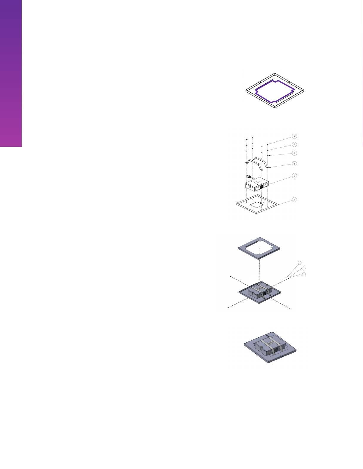
INSTALLATION - HARD-CEILING
VANTAGE I WITH ADAPTER PLATE
Installing Mounting Plate
1. Identify mounting location for unit. Use the mounting
plate (Figure 1) as a template to mark the cut-out area
where you’ll install your unit (area shown in purple).
2. Use a drywall saw to cut along the lines of the stencil
you drew. Then, drill the anchor holes from the
template.
3. Thread all four dry wall anchors through the mounting
plate.
4. Put the mounting plate into the ceiling, ensuring the
anchors match up to the holes.
5. Tighten the toggle bolt anchors.
Assembling Hard Ceiling Kit
6. Place the Vantage unit face down making sure that
the light engine and occupancy sensor ts within the
Vantage front plate cutout.
7. Attach the Vantage front plate to the Vantage unit
by securing with brackets and hardware as shown in
Figure 2.
8. Plug the unit into a standard 110V grounded outlet.
9. Insert the assembled kit into the mounting plate and
secure with hardware as shown in gure 3.
Figure 1
2Vantage Front Plate
Vantage Unit
Bracket (x2)
#8-32 Nut (x4)
Lock Washer #8 (x4)
Washer, Flat Plain #8 (x4)
Figure 2
Figure 3
1
3
2
Phillips Head Pan #6-32 x 5/16 (x4)
Lock Washer #6 (x4)
Washer, Flat Plain #6 (x4)
Completed Assembly

Each Vantage UV unit comes standard with mounting holes for standard VESA bracket. This enables
a variety of installation methods, including wire suspension and wall mounts.
1. When selecting a mounting bracket for wall-mounted deployment, the bracket should use a
100mm x 100mm VESA pattern and must be able to adequately handle the weight of the Vantage
unit (4 lbs Vantage I, 10 lbs Vantage II)
2. Attach the mounting bracket to the Vantage unit using the manufacturer-recommended
fasteners and method.
3. Secure mounting bracket to studs or using appropriate mounting hardware.
4. When positioning unit onto bracket, ensure proper air ow and clearance and to ensure nothing
blocks or interrupts the functioning of the PIR motion sensor.
The VESA holes also allow for integration with a variety of mobile stands, such as tripods or bases
with caster-wheels. See relevant user manuals for mobile kits for additional information.
PORTABLE DEPLOYMENT
© Copyright 2021 Violet Defense, LLC All Rights Reserved VNTG-USRMNL-2021
15
WALL-MOUNTED DEPLOYMENT
INSTALLATION - HARD-CEILING
VANTAGE I WITH ADAPTER PLATE
Phillips Head Pan #6-32 x 5/16 (x4)
The Vantage units can also be used in various rooms on tabletops, desks, counter tops, etc.
1. To ensure proper stability of the unit, handle unit with care to avoid dropping and place the unit
on a at, hard-surface away from any ammable items. It is recommended that users deploy the
Vantage I with its corresponding docking station. The unit should be positioned such that the
dock or any other items does not block the vents/fans on the unit.
2. Position the unit to ensure proper air ow and clearance and to ensure nothing blocks or
interrupts the functioning of the PIR motion sensor.
3. When using with portable mounts, be aware of stability of the assembly. Depending on the height
and weight, verify that the combined assembly does not tip over when tilted 10 degrees in any
direction. Inspect power cables for any prior damage from rollover or stepping on. Place or tape
down power cables to prevent a trip hazard.
PORTABLE DEPLOYMENT

UV GOVERNMENT GUIDELINES
© Copyright 2021 Violet Defense, LLC All Rights Reserved VNTG-USRMNL-2021
16
Occupational Safety and Health Administration (OSHA)
The Occupational Safety and Health Administration (OSHA) does not have any mandated exposure
limits to ultraviolet light. OSHA only provides technical guidance regarding protecting employees
from ultraviolet laser exposure. While general information about ultraviolet contained in that
guidance is described below, it is important to note that Violet Defense Technology does not
currently deploy ultraviolet lasers. For more information on OSHA’s guidelines, visit https://www.
osha.gov/pls/oshaweb/owadisp.show_document?p_table=INTERPRETATIONS&p_id=24755.
Ultraviolet radiation is divided into three regions: UV-A: 315-400 nanometers (nm), UV-B: 280-315
nm, and UV-C: 100-280 nm. UV can be associated with adverse health eects due to prolonged
exposure and the wavelength of light.
According to OSHA’s guidelines, “exposure in the shorter UV-C and longer UV-A ranges seems
less harmful to human skin. The shorter wavelengths are absorbed in the outer dead layers of
the epidermis and the longer wavelengths have an initial pigment-darkening eect followed by
erythema if there is exposure to excessive levels.”
“The hazards associated with skin exposure are of less importance than eye hazards.” Exposure to
light may cause photokeratitis or cataracts.
National Institute for Occupational Safety and Health (NIOSH)
The National Institute for Occupational Safety and Health (NIOSH) recommends limits to exposure
determined by the wavelength of UV light and intensity. NIOSH recommends that the time of
exposure to an intensity of 100 microwatts per square centimeter at wavelength 254 nm not exceed
1 minute. Per the programming, UV exposure from Vantage unit for a 30-minute cycle is less than
two seconds. For more information, view the recommended standards from NIOSH (https://www.
cdc.gov/niosh/docs/73-11009/pdf/73-11009A.pdf).
Environmental Protection Agency (EPA)
The Environmental Protection Agency (EPA) is the governmental agency responsible for regulating
ultraviolet light products. It regulates chemical disinfectants along with devices, such as equipment
that generates UV light, used to control pests like bacteria and making antimicrobial claims. For
more information about EPA guidelines, visit https://www.epa.gov/safepestcontrol/pesticide-
devices-guide-consumers.
Food and Drug Administration (FDA)
The Food and Drug Administration (FDA) only regulates devices that are classied as medical
instruments, machines, and devices used to treat diagnosed medical conditions. Therefore, Violet
Defense does not fall under FDA guidelines.
GOVERNMENTAL SAFETY CONSIDERATIONS FOR ULTRAVIOLET LIGHT

CONTACT US
Violet Defense
189 S Orange Avenue, Suite 1400, Orlando, FL 32801
+1.407.433.1104
This manual suits for next models
1
Table of contents
Other Violet Defense Lighting Equipment manuals


