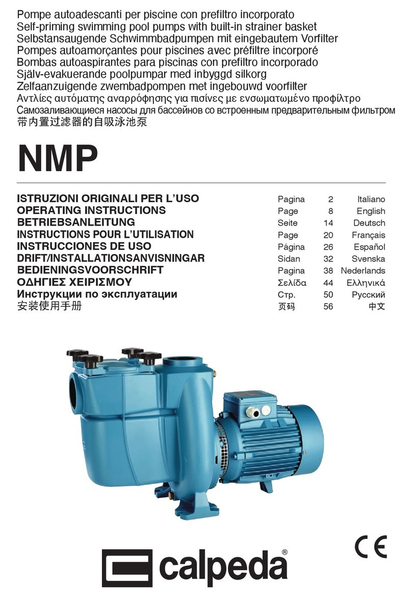
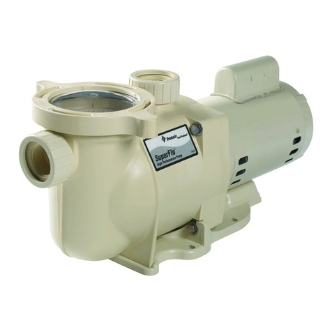
VIPool MCB Series User manual

DECLARATION DE CONFORMITE—DECLARATION OF CONFORMITY
AQUA CONSULT INDUSTRIE SERVICE
15 rue des Marais - 44310 ST Phi bert de Gd Lieu - FRANCE
Te : +33 (0)2 40 59 95 35 - Fax : +33(0)2 40 59 94 91
Déc aration de conformité ACIS déc are sous sa responsabi ité que es produits ACIS sont conformes aux directives européennes 2002/95/
CE (RoHS), 2004/108/CE, 2006/95/CE et 2006/42/CE (WEEE).
Dec aration of conformity, we, ACIS, dec are under our own responsibi ity that ACIS products comp y with the European directives
2002/95/CE (RoHS), 2004/108/CE, 2006/95/CE and 2006/42/CE (WEEE).
GB
F
Marc CHIRON
Hauteur/Height
(m)
Ref. A Volt
3 6 10 12 14 16 1
Débit/Flow rate
(m3/h)
MCB 4M 2 230 10 7 4
MCB 5M 2,7 230 13 10,5 8,5 5 3,5
MCB 5T 2/1,2 230/400
MCB 6M 2,9 230 13.5 11 9 6 3 1
MCB 6T 2/1,2 230/400
MCB 11M 3,8 230 17 15 13,4 11 8 4,5
MCB 11T 2,5/1,5 230/400
MCB 13M 4,4 230 19,5 17 15 13 10,5 7 3
MCB 13T 2,7/1,6 230/400
MCB 14,5M 4,6 230 20,5 18,5 16,5 14,5 12 9 4 2
MCB 14,5T 3,5/2 230/400
Pompes pour piscines - Série MCB
Guide de l’utilisateur
F
Swimming pool pumps - MCB series
User guide
GB
ACIS 06/11/2012

Ce document contient des informations fondamenta es pour a sécurité des personnes et des biens, ainsi
que sur a mise en service de a pompe. L’uti isateur et ’insta ateur doivent impérativement prendre
connaissance des informations contenues dans ce document avant ’insta ation et a mise en service.
Ce document de référence doit être conservé.
2
F
1. SIGNIFICATION DES SYMBOLES UTILISES DANS CE DOCUMENT
DANGER Risque d’é ectrocution
DANGER Risque de b essures pour es personnes
ATTENTION Risque de détérioration pour a pompe et ’insta ation
2. CONSIGNES GENERALES DE SECURITE
La liste des préconisations ci-dessous n’est pas limitative, toute manipulation de la pompe
doit se faire avec le maximum de précautions.
▪ La pompe a été conçue pour une uti isation sur un circuit fermé de fi tration de piscine, en eau
c aire et de température inférieure à 35° C.
▪ Ne pas modifier a pompe; toute modification de a pompe entraîne a perte de a garantie.
▪ Uti iser, pour toute réparation, exc usivement des pièces détachées fournies par e fabricant; ce ui-
ci déc ine toute responsabi ité en cas de dommages causés par ’uti isation de pièces de fabrication
extérieure ou modifiées sans son accord préa ab e.
▪ La sécurité et e bon fonctionnement de a pompe seront garantis si et seu ement si toutes es
instructions d’insta ation et de mise en service sont respectées.
▪ La pompe doit être insta ée en respectant es normes en vigueur dans e pays, en particu ier a
norme HD 384.7.702; i est consei é de faire appe à un professionne pour ’insta ation.
▪ Couper impérativement ’a imentation é ectrique de a pompe avant toute intervention.
▪ Les va eurs imites figurant sur e tab eau technique ne doivent jamais être dépassées, sous aucun
prétexte.
▪ En cas de disfonctionnement ou d’avarie, veui ez vous adresser au représentant du fabricant e
p us proche ou au Service d’Assistance Technique du fabricant.
▪ Surface chaude dans a zone moteur.
3. INSTALLATION ET MISE EN SERVICE
▪ Ne jamais faire fonctionner a pompe sans préfi tre.
▪ Ne jamais faire fonctionner a pompe sans eau.
▪ Votre pompe est équipée d’un panier préfi tre destiné à recuei ir es impuretés de grande tai e qui
pourraient endommager a turbine.
▪ Pour e bon fonctionnement de a pompe :
- Toujours faire fonctionner a pompe avec e préfi tre en p ace,
- La pompe doit être insta ée horizonta ement et fermement fixée.
▪ Le rendement est optimisé avec une pompe p acée sous e niveau de a piscine.
▪ Dans e cas d’une insta ation de a pompe au dessus du niveau d’eau de a piscine, a hauteur ne
doit pas exceder 1,5 m et a ongueur du tuyau d’aspiration devra être a p us courte possib e afin
d’éviter des temps d’aspiration et des pertes de charge trop importants (schéma n°1).
▪ Pour une bonne circu ation d’air et pour assurer un refroidissement efficace, a gri e du venti ateur
doit être située à p us de 30 cm d’un mur.
11
N° Désignation Designation
1 Vis de serrage Lock screw
2 Couvercle transparent Transparent cover
3 Joint torique d118*6 O'ring d118*6
4 Filtre Filter
5 Ecrou raccord Nut
6 Raccord à coller diamètre 50 Union Ø50
7 Joint torique d48*3,5 O'ring d48*3,5
8 Ecrou torillon Pivot nut
9 Corps de pompe Pump body
10 Bouchon de vidange Discharge nut
11 Joint torique d11,2*2,4 O'ring d11,2*2,4
12 Couvercle diffuseur Diffuser cover
13 Turbine Impeller
14 Garniture mécanique Mechanical seal
15 Joint torique d167,4*6,3 O'ring d167,4*6,3
16 Flasque pompe Pump cover
17 Rondelle d8 Washer d8
18 Vis M8*30 Bolt m8*30
19 Tampon Block gine
20 Support Bracket
21 Tampon Block gine
22 Couvercle ventilateur Fan cover
23 Vis M4*8 Bolt M4*8
24 Fixation Fixtion loop
25 Ventilateur Fan plate
26 Joint d’étanchéité d14x20 Axes mechanical seal d14,5x20
27 Flasque arrière Back end
28 Rondelle de compensation Washer
29 Roulement 6202 Bearing 6202
30 Rotor Rotor
31 Tirants M5*155 Bolt M5*155
32 Roulement 6203 Bearing 6203
33 Carcasse + stator Stator
34 Flasque avant Front end
35 Joint d’étanchéité d13*28 Shaft washer d13*28
36 Joint déflecteur d14*26 Retaining ring d14*26
37 Joint d'embase Wateroof mat
38 Boitier 0,5 à 1,5 CV Thermal up box
39 Bornier Terminal board
40 Vis ST3,5*16 Bolt ST3,5*16
41 Bride Cable Block
42 Vis ST3,5*13 Bolt ST3,5*13
43 Condensateur Capacitor
44 Protection condensateur DM paper
45 Bride condensateur Capacitor gland
46 Joint torique de bornier d120*2 O'ring d120*2
47 Couvercle de bornier Thermal up box
10
Pompe
MCB
3
3.1 BRANCHEMENTS ELECTRIQUES
▪ Vérifier que a tension et a fréquence du réseau é ectrique correspondent aux va eurs indiquées
sur a p aque de a pompe.
▪ L’insta ation é ectrique de a pompe doit être dotée d’un protecteur différentie dont a va eur ne
dépasse pas 30mA.
▪ Lors du raccordement é ectrique de a boîte à bornes du moteur de a pompe, s’assurer du bon
serrage des cosses é ectriques et raccorder correctement a prise de terre.
▪ Vérifier que e rég age du re ais thermique de ’armoire é ectrique soit adaptée à ’intensité du
moteur de a pompe afin d’assurer une protection efficace de ce ui-ci (voir a p aque de a pompe).
▪ Boîte à bornes de pompe monophasée ▪ Boîte à bornes de pompe triphasée
▪ Dans e cas d’un moteur triphasé : vérifier que e moteur tourne dans e sens des aigui es d’une
montre (en regardant e venti ateur - voir f èche sur e capot du venti ateur).
▪ Ni e moteur, ni aucun composant sous tension é ectrique ne doit entrer en contact avec ’eau.
▪ Vérifier ’iso ation des câb es é ectriques.
▪ Vérifier e bon positionnement du câb e à ’entrée de a boîte à bornes afin d’éviter toute entrée
d’eau par e passage du fi .
3.2 INSTALLATION HYDRAULIQUE
▪ Raccorder a pompe au circuit hydrau ique de a piscine à ’aide des raccords fournis.
▪ Pour e raccordement des tuyaux à a pompe, es unions sont fournies avec des joints toriques à
uti iser impérativement.
▪ La connexion des tuyaux aux raccords fournis doit être effectuée par co age.
▪ Le tuyau de refou ement devra être insta é perpendicu airement et parfaitement centré par
rapport aux bouches à connecter, de façon à éviter que a
pompe et e tuyau ne soient soumis à des efforts externes qui,
indépendamment des opérations de montage, pourraient
arriver à en causer a rupture. Une ongueur de tuyauterie
vertica e (environ 60 cm) est consei ée pour faci iter
’amorçage de a pompe.
▪ Une égère inc inaison des tuyaux d’aspiration (2%) évite a
formation de poche d’air.
F
Schéma n°1
Max : 1,5m

4
F
3.3 MISE EN ROUTE, AMORCAGE
▪ Position des vannes : aspiration et refou ement fermées.
1 - Couper ’a imentation é ectrique de a pompe.
2 - Remplir impérativement d’eau le préfiltre
3 - Revisser e couverc e en s’assurant que e joint ne soit ni pincé ni déterioré.
4 - Remettre ’a imentation é ectrique.
5 - Démarrer a pompe
6 - Aussitôt ouvrir entement a vanne d’aspiration, puis de refou ement.
▪ La pompe doit s’amorcer en que ques minutes; à défaut reprendre cette opération au début.
3.4 FONCTIONNEMENT, INTERVENTION
▪ La pompe doit fonctionner sans bruit, ni vibration.
▪ Vérifier périodiquement ’absence de fuite.
▪ Nettoyer périodiquement e panier du préfi tre.
▪ Toujours stopper a pompe avant de manœuvrer a vanne de votre fi tre (6 voies) sur e circuit hydrau ique de a
piscine.
▪ Cette é ectropompe piscine est équipée de série avec une poche fi trante soup e (P.F.S.) insérée dans e panier du
préfi tre. Ce e-ci est destinée à b oquer es impuretés fines (graviers, sab e, aigui es de pin, etc) qui viennent
généra ement a térer e bon fonctionnement des pompes. La 1ère mise en route, a présence dans e bassin de sab e
ou d’aigui e de résineux, ’uti isation d’un ba ai manue sont des cas où ’uti isation de cette P.F.S. est
indispensable. Nous vous consei ons donc de aisser en p ace cette option en permanence avec bien sûr un
contrô e et un nettoyage régu ier de ce e-ci (au minimum 1 fois par semaine). Si ’é ectropompe nous revient en SAV
pour un b ocage de a turbine provenant d’impuretés supérieures au tamisage de a poche fi trante soup e, e prise
en garantie ne s’app iquera pas.
Par ’intermédiaire de votre revendeur, i est possib e de se procurer des P.F.S. supp émentaires.
3.5 INTERVENTION
▪ Risque de b essures pour es personnes n’ayant pas a qua ification requise. Les travaux de réparation et de
maintenance doivent être effectués par un personne spécia ement formé.
Pour toute intervention sur a pompe:
- Couper ’a imentation é ectrique
- S’assurer que ’interrupteur est en position « arrêt »
- Attendre que e moteur soit comp ètement arrêté.
▪ La garniture mécanique est un composant vita de a pompe. Son remp acement doit être effectué avec e p us
grand soin. I est préférab e de confier cette opération à un spécia iste
▪ Démontage/Remontage : Prendre es précautions nécessaire pour éviter de se coincer es mains et es pieds
- Nettoyer et contrô er toutes es pièces avant eur remontage.
- Impérativement remp acer es pièces usées ou endommagées.
- Vei ez à a propreté et à a position des joints. I est consei é de ne remonter que des joints neufs.
▪ Pour toute commande de pièces détachées, indiquer e type de a pompe (p aque), e numéro de série de a
pompe (p aque), e numéro de repère de a pièce (vue éc atée) et a désignation de a pièce (tab eau et vue éc atée)
3.6 HIVERNAGE
▪ La pompe doit être vidée par e bouchon de vidange pour une mise hors ge .
3.7 REMISE EN ROUTE APRES L’HIVER
▪ I faut :
1 - Couper ’a imentation é ectrique.
2 - Engager un tournevis p at dans e trou au centre du capot venti ateur.
3 - Faire tourner ’arbre moteur manue ement.
4 - En ever e tournevis
5 - Mettre en route (voir § 3.3 MISE EN ROUTE, AMORCAGE).
9
GB
4. TROUBLESHOOTING
5. MINIMUM OPERATING PRESSURES
Exp anation: It is vita that you check the pressures specified above when commissioning the pump. In
fact, a pressure be ow these minimum va ues eads to the premature wearing of the pump assemb y.
Setting: C ose the de ivery va ve progressive y in order to achieve the minimum pressure that corre-
sponds to your mode .
Pressure in the water
column height Pressure in Bar Pressure in g
(grams)
MCB pump
5 2 0.2 200
6 2 0.2 200
11 2 0.2 200
13 2.5 0.25 250
14,5 2.5 0.25 250
Model
FAULTS
PROBABLE CAUSES
SOLUTIONS
The pump won’t
prime
Air eak a ong the suction pipe
Check the condition of the coup ings and sea s
a ong the suction pipe
Cover incorrect y fastened
C ean the cover and check the condition of the
sea
Incorrect motor revo ution direc-
tion (three-phase motor)
Invert 2 phases on the e ectricity supp y
Weak pump out-
put
Prefi ter c ogged
C ean the prefi ter
Air eak a ong the suction pipe
Check the condition of the coup ings and sea s
a ong the suction pipe
Incorrect motor revo ution direc-
tion (three-phase motor)
Invert 2 phases on the e ectricity supp y
Pressure oss in the suction
Avoid: ong pipes, numerous e bows, positioning
the pump higher than the water eve , narrow
pipes
Incorrect vo tage
Make sure the vo tage in your supp y corre-
sponds to the va ue specified on the motor data
p ate
The motor
stops
Make sure the fan grid is free of obstac es (at
east 30 cm c earance between the wa and the
fan)
Increase the pump’s operating pressure by
s ight y c osing the de ivery va ve (see tab e be-
ow)
Noise/vibration
Cavitation
See paragraph 5
Foreign body (sand, etc)
Dismount, c ean, reassemb e
Motor overheat

8
GB
3.3 COMMISSIONING, PRIMING
▪ Position of va ves: suction c osed, de ivery c osed.
1 - Cut off the e ectricity supp y to the pump.
2 - Fill the prefilter with water (imperative)
3 - Screw the cover back on, making sure the sea is neither c amped nor worn.
4 - Switch the e ectricity back on.
5 - Start the pump
6 - Immediate y, open the suction va ve and s ow y the de ivery va ve
▪ The pump shou d be primed within a few minutes; if not, start again.
3.4 OPERATION
▪ The pump shou d operate without making any noise or vibrations.
▪ Check for any eaks on a regu ar basis.
▪ C ean the prefi ter basket on a regu ar basis.
▪ A ways stop the pump before hand ing the va ve on your fi ter (6-way) on the swimming poo ’s hydrau ic circuit.
▪ This e ectrica poo pump is fitted as standard with a f exib e fi ter bag inserted in the pre-fi ter basket. This is
intended to trap fine impurities (grave , sand, pine need es, etc.) which can often prevent pumps from operating
correct y. When using the pump for the first time, when there is sand or pine need es present in the poo , or if a
manua broom has been used, these are situations where the use of the f exib e fi ter bag is essentia . We there-
fore advise you to eave this option permanent y in position and, of course, to check and c ean it regu ar y (at
east once a week). If the e ectrica pump is returned to us for after-sa es service due to a b ockage of the turbine
from impurities arger than the f exib e fi ter bag’s straining capabi ity, the item wi not be repaired under war-
ranty.
You can obtain additiona f exib e fi ter bags from your usua supp ier.
3.5 INTERVENTION
Risk of injury to persons without the required qua ifications. Repair and maintenance work must be carried out
by specia y trained personne .
▪ When working on the pump:
- Cut off the e ectricity supp y
- Make sure the switch is set to “off”
- Wait for the motor to have come to a comp ete stop.
▪ The mechanica sea is a vita component of the pump. It shou d be rep aced with the utmost care. It is advis-
ab e to contact a specia ist for this task.
▪ Disassemb y/Re-assemb y: Take the necessary precautions to avoid trapping your hands or feet.
- C ean and check a parts before reassemb ing them.
- Rep ace a worn or damaged parts (imperative).
- Make sure the sea s are c ean and in the correct position. We recommend you on y reposition new sea s.
▪ In a spare part orders, p ease specify:
- The type of pump (data p ate)
- The pump’s seria number (data p ate)
- The part’s position number (exp oded view)
- The name of the part (tab e and exp oded view)
3.6 WINTERING
▪ The pump must be emptied through the p ugho e for anti-freezing purposes.
3.7 RECOMMISSIONING AFTER THE WINTER
▪ Proceed as fo ows:
1 - Cut off the e ectricity supp y.
2 - Insert a f at-headed screwdriver in the s ot in the centre of the fan cover.
3 - Rotate the motor shaft manua y.
4 - Remove the screwdriver
5 - Start the pump (see § 3.3 COMMISSIONING, PRIMING).
5
F
4. EVENTUELS DEFAUTS, CAUSES ET SOLUTIONS
5. PRESSIONS MINIMALES DE FONCTIONNEMENT
Exp ication : I est impératif de vérifier es pressions indiquées ci-dessus ors de a mise en service. En
effet, une pression inférieure à ces va eurs minimum conduit à une usure prématurée de ’ensemb e de a
pompe.
Rég age : Fermer progressivement a vanne de refou ement afin d’obtenir a pression minimum
correspondante au modè e.
Pression mCE Pression Bar Pression g
MCB
5 2 0.2 200
6 2 0.2 200
11 2 0.2 200
13 2.5 0.25 250
14.5 2.5 0.25 250
Modèle
DEFAUTS CAUSES PROBABLES SOLUTIONS
La pompe ne
s’amorce pas
Prise d’air sur a tuyauterie d’aspi-
ration
Vérifier ’état des raccords et des joints sur a
tuyauterie d’aspiration
Mauvais serrage du couverc e Nettoyer e couverc e et vérifier ’état du joint
Sens de rotation du moteur incor-
rect (moteur triphasé)
Intervertir 2 phases sur ’a imentation é ectrique
Faib e débit de a
pompe
Préfi tre bouché Nettoyer e préfi tre
Prise d’air sur a tuyauterie d’aspi-
ration
Vérifier ’état des raccords et des joints sur a
tuyauterie d’aspiration
Sens de rotation du moteur incor-
rect (moteur triphasé)
Intervertir 2 phases sur ’a imentation é ectrique
Pertes de charges dans ’aspiration A éviter: grande ongueur de tuyau, nombreux
coudes, é évation de a pompe au dessus du
niveau d’eau, cana isations trop petites
Mauvaise tension Vérifier que a tension de votre réseau corres-
pond à ce e indiquée sur a p aque des caracté-
ristiques moteur
Le moteur
s’arrête
Vérifier que a gri e du venti ateur est dégagée
(distance mur/venti ateur au moins 30 cm)
Augmenter a pression de fonctionnement de a
pompe en fermant un peu a vanne de refou e-
ment (voir tab eau ci-après)
Bruit/vibration
Cavitation Voir paragraphe 5
Corps étrangers (sab e, …) Démontage, nettoyage, remontage
Surchauffe du moteur

This document contains some very important information for the safety of individua s and of property, as
we as on how to commission the pump. The user and insta er must under a circumstances fami iarise
themse ves with the information contained herein prior to insta ing and commissioning the device.
P ease keep this reference document at hand.
6
GB
1. MEANING OF THE SYMBOLS USED HEREIN
DANGER Risk of e ectrocution
DANGER Risk of persona injury
WARNING
Risk of pump and system deterioration
2. GENERAL SAFETY INSTRUCTIONS
The instructions listed below are purely indicative and in no way limited. The pump must
always be handled with the utmost care.
▪ The pump was designed for use in a c osed swimming poo fi tering circuit, in c ean water at a
temperature of ess than 35° C.
▪ Do not modify the pump in any way; the guarantee wi automatica y be inva idated in the event
of a pump modification.
▪ For a repair work, on y use spare parts supp ied by the manufacturer; the atter wi not be he d
iab e in the event of damage caused by the use of non origina spare parts or parts which have
been modified without prior approva of the manufacturer.
▪ The safety and correct operation of the pump are guaranteed on y if a the insta ation and com-
missioning instructions have been fo owed.
▪ The pump must be insta ed in comp iance with the app icab e standards in force in the country
of insta ation and use, especia y HD 384.7.702; we recommend you contact a professiona for the
pump insta ation.
▪ Cut off the e ectricity supp y to the pump prior to any intervention.
▪ The imits specified in the technica data tab e must never be exceeded under any circum-
stances.
▪ In the event of a ma function or fai ure, p ease contact your nearest manufacturer’s representa-
tive or the manufacturer’s Technica Support Service.
▪ Hot surface in the area around the motor
3. INSTALLATION AND COMMISSIONING
▪ Never operate the pump without the prefi ter.
▪ Never operate the pump without any water.
▪ Your pump is fitted with a prefi ter basket designed to co ect any arge impurities which cou d
damage the turbine.
▪ To ensure the correct operation of the pump:
- A ways operate the pump with the prefi ter in p ace,
- The pump must be insta ed horizonta y and secured in p ace.
▪ Its performance is optimised if the pump is positioned be ow the swimming poo ’s water eve .
▪ If the pump has to be insta ed above the swimming poo ’s water eve , the height must not ex-
ceed 1,5 m and the ength of the suction pipe wi have to be as short as possib e in order to avoid
significant suction times and pressure osses (diagram no. 1).
▪ For the correct air circu ation and to ensure effective coo ing, the fan grid must be ocated more
than 30cm from a wa
.
7
3.1 ELECTRICAL CONNECTIONS
▪ Make sure the e ectricity supp y vo tage and frequency correspond to the va ues specified on the
pump data p ate.
▪ The pump’s e ectrica system must be fitted with a differentia guard with a va ue of no more than
30mA.
▪ When wiring the pump motor termina board, make sure the e ectrica termina s are tightened
proper y and make the earthing connection correct y.
▪ Check that the adjustment of the therma re ay in the e ectrica cabinet matches the pump motor
intensity in order to ensure the effective protection of the atter (see the pump data p ate).
▪ Sing e-phase pump termina board ▪ Three-phase pump termina board
▪ In the event of a three-phase motor: make sure the motor is revo ving c ockwise ( ooking at the
fan - see the arrow on the top of the fan).
▪ Neither the motor nor any of the ive parts must come into contact with water.
▪ Make sure the e ectrica wires are sheathed.
▪ Check the correct positioning of the cab e at the termina board input in order to avoid any water
seeping in through the wire passage.
3.2 HYDRAULIC SYSTEM
▪ Connect the pump to the swimming poo ’s hydrau ic circuit using the coup ings provided.
▪ To connect the pipes to the pump, the joints are supp ied with O-rings which must under a cir-
cumstances be used.
▪ The pipes must be connected to the coup ings and g ued in p ace.
▪ The de ivery pipe must be fitted at a right ang e and perfect y centred with respect to the out ets
to be connected, so as to avoid the pump and pipe from being
subjected to externa stresses which cou d cause them to
break, irrespective of the assemb y operations. We recommend
a vertica pipe ength of approx. 60cm to faci itate the priming
of the pump.
▪ A s ight ti t of the suction pipes (2%) wi prevent any air
pockets from forming.
GB
Diagram no. 1
Max : 1,5m
This manual suits for next models
11
Table of contents
Other VIPool Swimming Pool Pump manuals
Popular Swimming Pool Pump manuals by other brands

Polygroup
Polygroup SUMMER WAVES SKIMMERPLUS SFX330 owner's manual

baracuda
baracuda titan 2 Eco 3 Installation & operating instructions

Hayward
Hayward PowerFlo Matrix owner's manual

Gardena
Gardena RP 240 operating instructions

Bestway
Bestway FLOWCLEAR 58391 owner's manual

Pentair
Pentair SWIMMEY Series installation guide

Espa
Espa NOXPLUS instruction manual

Polygroup
Polygroup SUMMER WAVES RX600 owner's manual

Theralux
Theralux Theratherm User and service manual

Intex
Intex DP30110 owner's manual

Little Giant
Little Giant APCP-1700 owner's manual

aqua technix
aqua technix AQUA Master Series Original installation and operating manual