- 1 -
Welcome to use Around View Monitoring System, hereafter referred as AVM. The operating
instruction manual explains the required items for proper use of AVM, please read it carefully. Note that
the sketches shown in the instruction are illustrative only and please refer to full-scale production for
actual use
1. Safety Protection
In order to insure the safety use of the product, please be careful to read the following required
items:
1. This product is driving auxiliary equipment only and therefore can not replace the actual
observation of eyes. It may result in serious traffic accident if over depending on the system.
2. The camera viewing angle is relatively large, therefore, this product cannot fully display actual
conditions, please be careful to use it before you are familiar with.
3. Don’t operate this system when driving at high speed in order to avoid accidents due to distraction.
4. Don’t place the product in humid conditions in order to avoid short circuit raised by electric shock
and fire.
5. Please apply the system under operating voltage.
6. The output voltage of the host is 3.3V, only serve for the camera. Please don’t load any
undesignated or allowed equipments.
2. Product description
AVM collects images around automobiles, after series of intelligent algorithm processing, the
panorama overhead view of a vehicle is shown on the screen, which displays relevant locations and
around conditions directly. The system, to a great extend, expands drivers’ environment perceptions, so
they can deal with parking and narrow road entrances, and barriers easily with decreased traffic
accidents such as scraping cars.
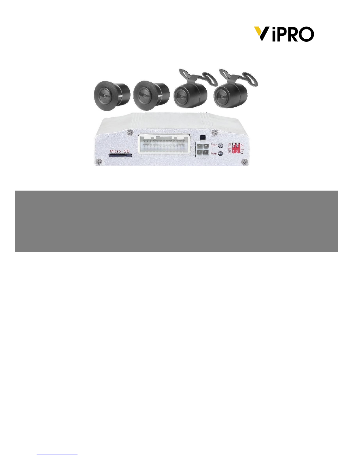
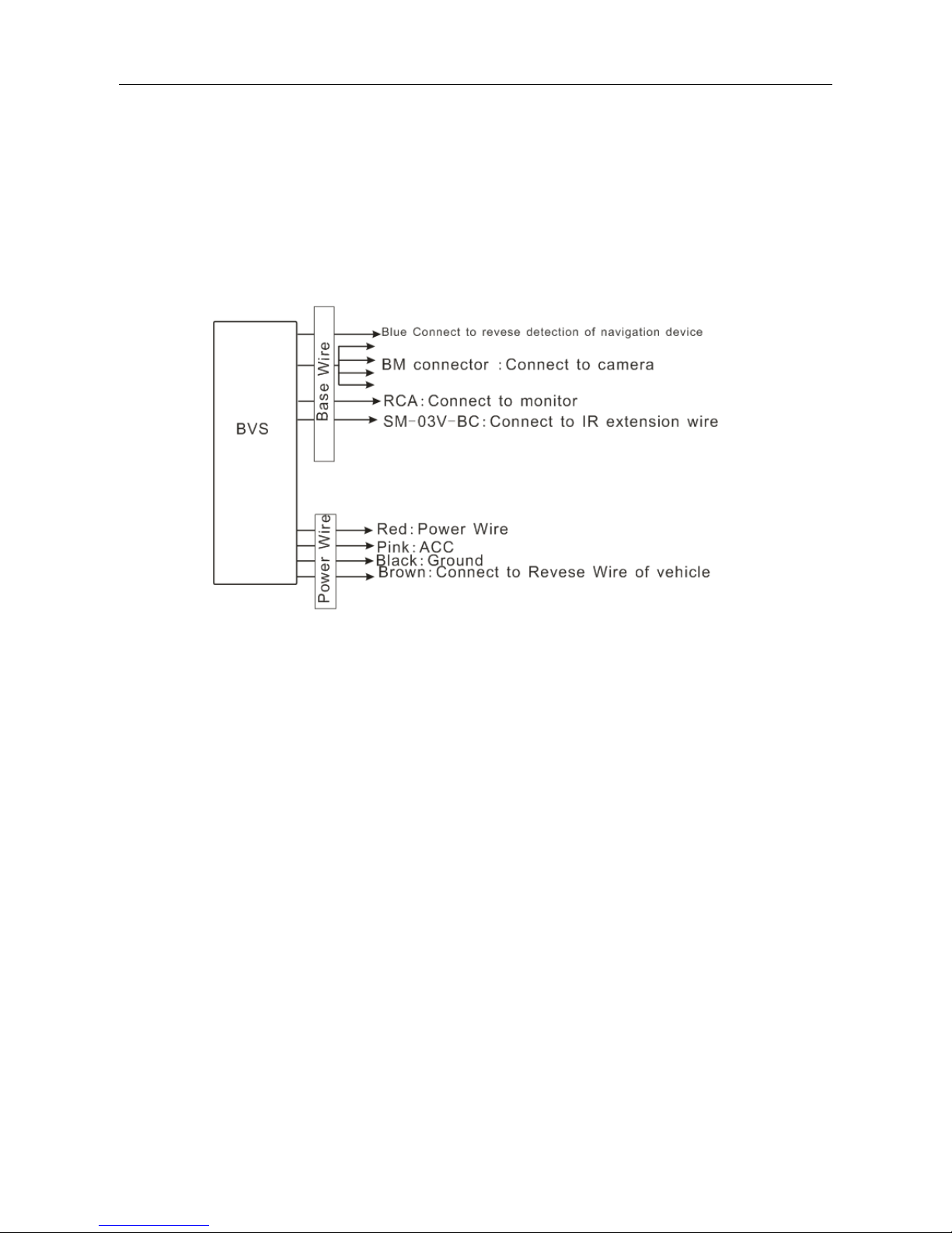
3. Product composition
AVM contains an image processing unit and four ultra-wide cameras, as shown in figure 3.1. Usually,
the left and right camera are installed in left and right rearview mirror, the front and back camera are
installed above the front and back bumpers. According to various types of vehicles, the appearance and
installation spot are different as well.
Fig 3.1 AVM composition
User Manual - AVM100 l v1.2 l 2014.03
ViPRO by Mobile Cloud Corporation