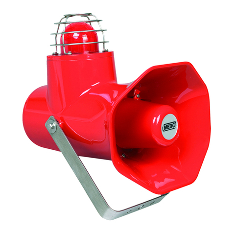
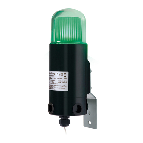
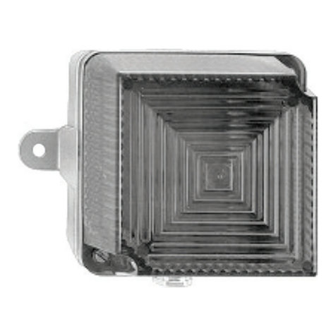
Eaton FHF DSLB 20 LED User manual

DSLB 20 LED Beacon Technical Manual
Eaton MEDC technical manual

2DSLB 20 BEACON TECHNICAL MANUAL TMF0053.A www.eaton.com
DISCLAIMER OF WARRANTIES AND LIMITATION OF LIABILITY
ENGLISH
The information, recommendations, descriptions and safety notations in this document are based on Eaton Corporation’s (“Eaton”)
experience and judgment and may not cover all contingencies. If further information is required, an Eaton sales office should be consulted.
Sale of the product shown in this literature is subject to the terms and conditions outlined in appropriate Eaton selling policies or other
contractual agreement between Eaton and the purchaser.
THERE ARE NO UNDERSTANDINGS, AGREEMENTS, WARRANTIES, EXPRESSED OR IMPLIED, INCLUDING WARRANTIES OF FITNESS
FOR A PARTICULAR PURPOSE OR MERCHANTABILITY, OTHER THAN THOSE SPECIFICALLY SET OUT IN ANY EXISTING CONTRACT
BETWEEN THE PARTIES. ANY SUCH CONTRACT STATES THE ENTIRE OBLIGATION OF EATON. THE CONTENTS OF THIS DOCUMENT
SHALL NOT BECOME PART OF OR MODIFY ANY CONTRACT BETWEEN THE PARTIES.
In no event will Eaton be responsible to the purchaser or user in contract, in tort (including negligence), strict liability or other-wise for any
special, indirect, incidental or consequential damage or loss whatsoever, including but not limited to damage or loss of use of equipment,
plant or power system, cost of capital, loss of power, additional expenses in the use of existing power facilities, or claims against the
purchaser or user by its customers resulting from the use of the information, recommendations and descriptions contained herein. The
information contained in this manual is subject to change without notice.
DEUTSCH
Die Informationen, Empfehlungen, Beschreibungen und Sicherheitshinweise in dieser Dokumentation basieren auf den Erfahrungen
und der Bewertung der Eaton Corporation („Eaton“) und sind unter Umständen nicht allumfassend. Wenden Sie sich bitte für weitere
Informationen an eine Vertriebsniederlassung von Eaton. Der Verkauf des in dieser Informationsschrift gezeigten Produkts unterliegt den
Allgemeinen Geschäftsbedingungen in den entsprechenden Eaton-Verkaufsrichtlinien oder sonstigen vertraglichen Vereinbarungen zwischen
Eaton und dem Käufer.
ES BESTEHEN KEINE VEREINBARUNGEN, VERTRÄGE ODER GEWÄHRLEISTUNGEN, EINSCHLIESSLICH GARANTIEN DER
GEBRAUCHSTAUGLICHKEIT FÜR EINEN BESTIMMTEN ZWECK ODER MARKTFÄHIGKEIT, AUSSER DEN KONKRET IN EINEM
ZWISCHEN DEN VERTRAGSPARTNERN BEREITS BESTEHENDEN VERTRAG DEFINIERTEN. JEDER DIESER VERTRÄGE BENENNT ALLE
PFLICHTEN VON EATON. DER INHALT DES VORLIEGENDEN DOKUMENTS WIRD NICHT TEIL EINES VERTRAGES ZWISCHEN DEN
PARTEIEN UND ÄNDERT DIESEN AUCH NICHT.
In keinem Fall ist Eaton gegenüber dem Käufer oder Benutzer vertraglich, aus unerlaubter Handlung (einschließlich Fahrlässigkeit),
verschuldensunabhängiger Haftung oder anderweitig für besondere, indirekte, zufällige oder Folgeschäden oder -verluste jeglicher
Art verantwortlich, einschließlich, aber nicht beschränkt auf Schäden oder Nutzungsausfall von Geräten, technischen Anlagen oder
Stromversorgungssystemen, Kapitalkosten, Stromausfall, zusätzliche Ausgaben bei der Nutzung vorhandener Stromanlagen oder
Ansprüche gegen den Käufer oder Benutzer durch seine Kunden, die sich aus der Nutzung der hierin enthaltenen Informationen,
Empfehlungen und Beschreibungen ergeben. Eaton behält sich Änderungen der Angaben in diesem Handbuch ohne vorherige
Ankündigung vor.
FRANCAIS
Les informations, recommandations, descriptions et indications de sécurité dans ce document sont basées sur l’expérience et le jugement
d’Eaton Corporation (“Eaton”) et peuvent ne pas couvrir toutes les éventualités. Si des informations supplémentaires sont nécessaires,
consultez un bureau de vente Eaton. La vente du produit décrit dans ce document est soumise aux conditions générales décrites dans les
politiques commerciales d’Eaton ou l’accord contractuel entre Eaton et l’acheteur.
IL N’Y A PAS ENTENTE, ACCORD, GARANTIE, EXPLICITE OU IMPLICITE, Y COMPRIS DE GARANTIE D’ADAPTATION À UN USAGE
PARTICULIER OU DE QUALITÉ MARCHANDE, AUTRES QUE CEUX SPECIFIÉS DANS TOUT CONTRAT EXISTANT ENTRE LES PARTIES.
UN TEL CONTRAT DÉCRIT L’ENGAGEMENT COMPLET D’EATON. LE CONTENU DE CE DOCUMENT NE DOIT PAS DEVENIR PARTIE OU
MODIFIER TOUT CONTRAT ENTRE LES PARTIES.
En aucun cas Eaton ne saura être tenu responsable par l’acheteur ou par l’utilisateur partie au contrat, à tort (négligence comprise) d’une
responsabilité stricte ni de tout autre dommage ou perte particulier, indirect, accidentel ou conséquentiel, de quelque type que ce soit,
y compris sans y être limité tout dommage ou perte d’utilisation de l’équipement, de l’usine ou du système d’alimentation, du coût de
capital, de la perte de puissance, des dépenses supplémentaires engendrées par l’utilisation de systèmes d’alimentation existants, ni de
toute réclamation par des clients à l’acheteur ou à l’utilisateur résultant de l’utilisation des présentes informations, recommandations et
descriptions.. Les informations contenues dans ce manuel sont sujettes à modification sans préavis.
PORTUGUÊS
As informações, recomendações, descrições e notações de segurança incluídas neste documento são baseadas na experiência e avaliação
da Eaton Corporation («Eaton»), e podem não abranger todas as contingências. Se forem necessárias mais informações, deve consultar
um escritório de vendas da Eaton. A venda do produto apresentado nesta documentação está sujeita aos termos e condições descritos
nas políticas de venda apropriadas da Eaton ou noutro acordo contratual entre a Eaton e o comprador.
NÃO EXISTEM ENTENDIMENTOS, ACORDOS, GARANTIAS, EXPRESSAS OU IMPLÍCITAS, INCLUINDO GARANTIAS DE ADEQUAÇÃO A
UM DETERMINADO FIM OU COMERCIALIZAÇÃO, PARA ALÉM DOS ESPECIFICAMENTE ESTABELECIDOS EM QUALQUER CONTRATO
EXISTENTE ENTRE AS PARTES. QUALQUER CONTRATO SEMELHANTE ESTABELECE A OBRIGAÇÃO TOTAL DA EATON. O CONTEÚDO
DO PRESENTE DOCUMENTO NÃO SE TORNARÁ PARTE NEM MODIFICARÁ QUALQUER CONTRATO ENTRE AS PARTES.
Em nenhuma circunstância a Eaton será responsável perante o comprador ou utilizador em contrato, por delito (incluindo negligência),
responsabilidade estrita ou, de outro modo, por qualquer dano ou perda especial, indireta, incidental ou consequencial, incluindo, sem
limitação, danos ou perda de utilização de equipamentos, instalações ou sistemas de energia, custo de capital, perda de energia, despesas
adicionais no uso de instalações elétricas existentes, ou reivindicações contra o comprador ou utilizador por parte dos clientes resultantes
da utilização de informações, recomendações e descrições presentes neste documento. As informações contidas neste manual estão
sujeitas a alterações sem aviso prévio.
3DB3BM SOUNDER TECHNICAL MANUAL TM276.A www.eaton.com
Table of contents
Ex-LED Luminary (2G, 2D) dSLB20-LED...............................................................4
Dimensions .....................................................................................4
Application......................................................................................4
Design..........................................................................................4
Setting the operating modes .......................................................................4
Connecting the operating voltage ...................................................................4
Maintenance and servicing.........................................................................5
Terminal room ...................................................................................5
Wall mounting ...................................................................................5
Technical Specifications ...........................................................................6
User Information .................................................................................7
Cable gland .....................................................................................8
Table of Contents

4
DSLB 20 LED Beacon Technical Manual
DSLB 20 LED BEACON TECHNICAL MANUAL TMF0053.A www.eaton.com
Ex-LED Luminary (2G, 2D) dSLB20-LED
Dimensions
Application
Hazardous areas often require the use of optical signals for warning, information or signalling purposes. The dSLB20-
LED provides these signalling options. The available operating modes are Continuous light, Strobe light, Blinking light
and Rotating light, and turning on the supply voltage activates the device. The dSLB20-LED is equipped with high
performance light-emitting diodes (LEDs) and comes in the colours white, red, yellow, green and blue. The stable
housing conforms to protection degree IP66 / IP67 and is suitable for both indoor and outdoor use.
Design
The dSBL20-LED consists of a small, flameproof housing of (sea water resistant) aluminium with a glass dome of hardened
borosilicate glass to accommodate the electronics. The terminal room has been designed according to the ‘increased
safety’ type of protection.
Setting the operating modes
The operating modes are set using a rotary switch on the circuit board located within the housing. Proceed as follows:
unfasten the special locking screw on the side of the device, unscrew the upper part of the housing and remove it. See
also User information, paragraph 9. After setting the operating mode, screw the upper part of the housing carefully back
onto the lower part. Screw the special locking screw back in.
Advice: Before you screw the upper part of the housing onto the lower part, spread resin free lubricating oil on the
thread.
Connecting the operating voltage
Open the terminal room on the underside of the dSBL20-LED. Lay the connecting cable through the cable gland, secure
the connecting cable using the cable gland nut and arrange the conductor ends (see drawing of the terminal room). The
dSLB20-LED comes in a direct current 24 VDC / 48 VDC version and in an alternating current 85 – 265 VAC version.
In the case of the direct current version, please observe the polarity of the connections. For the alternating current
version, the cable ends can be randomly connected. Connect the protective conductor to the Protective Earth terminal.
Then close the terminal room with the terminal room lid.
• Robust, flameproof optical signalling LED technology device of
Device Group II for use in explosive atmospheres, zones 1 and 2 or
zones 21 and 22.
• The version “Continuous light, colour red” fulfills the requirements
of Convention on International Civil Aviation ICAO, Annex 14,
Obstruction Light, Low Intensity, Type A, red

5
DSLB 20 LED Beacon Technical Manual
DSLB 20 LED BEACON TECHNICAL MANUAL TMF0053.A www.eaton.com
Maintenance and servicing
The equipment does not contain any parts that needed maintaining. The specifications of EN 60079-17 concerning the
regular checking of explosion protection are to be complied with.
Terminal room Wall mounting
Switch-position Operating mode
0Continuous light
1Blinking light
2Strobe light (as-deliv. condition)
3Rotating light 1; 1 LED segment on
4Rotating light 2; 2 LED segments on
5 - 9 Strobe light
A - F Strobe light

6
DSLB 20 LED Beacon Technical Manual
DSLB 20 LED BEACON TECHNICAL MANUAL TMF0053.A www.eaton.com
Technical Specications
Optical
specifications White Colour location: x=0,33; y=0,33 according to CIE 1931, Typical colour temperature: 5600 K;
colour rendering index: 80; brightness app. 24 cd
Red Wavelength: 625 nm; brightness app. 31 cd
Yellow Wavelength: 587 nm; brightness app. 13 cd
Green Wavelength: 528 nm; brightness app. 53 cd
Blue Wavelength: 470 nm; brightness app. 17 cd
Operating voltage DC voltage 24 VDC ± 20 % ou 48 VDC ± 20%
Alternating current 85 – 265 VAC
red yellow green blue white
Power consumption
24 VDC
Continuous app. 550 mA app. 570 mA app. 800 mA app. 850 mA app. 870 mA
Blinking light (LEDs on) app. 550 mA app. 570 mA app. 800 mA app. 850 mA app. 870 mA
Strobe light (LEDs on) app. 1,2 A app. 1,2 A app. 1,5 A app. 1,5 A app. 1,6 A
Rotating light 1 app. 190 mA app. 190 mA app. 250 mA app. 250 mA app. 280 mA
Rotating light 2 app. 250 mA app. 250 mA app. 350 mA app. 350 mA app. 380 mA
Power consumption
48 VDC
Continuous app. 225 mA app. 235 mA – – –
Blinking light (LEDs on) app. 225 mA app. 235 mA – – –
Strobe light (LEDs on) app. 650 mA app. 650 mA – – –
Rotating light 1 app. 115 mA app. 115 mA – – –
Rotating light 2 app. 140 mA app. 140 mA – – –
Power consumption
230 VAC
Continuous app. 125 mA app. 125 mA app. 160 mA app. 170 mA app. 170 mA
Blinking light (LEDs on) app. 125 mA app. 125 mA app. 160 mA app. 170 mA app. 170 mA
Strobe light (LEDs on) app. 180 mA app. 180 mA app. 210 mA app. 230 mA app. 230 mA
Rotating light 1 app. 60 mA app. 60 mA app. 65 mA app. 70 mA app. 70 mA
Rotating light 2 app. 70 mA app. 70 mA app. 80 mA app. 85 mA app. 85 mA
Power consumption
120 VAC
Continuous app. 190 mA app. 190 mA app. 250 mA app. 280 mA app. 280 mA
Blinking light (LEDs on) app. 190 mA app. 190 mA app. 250 mA app. 280 mA app. 280 mA
Strobe light (LEDs on) app. 280 mA app. 280 mA app. 360 mA app. 390 mA app. 420 mA
Rotating light 1 app. 80 mA app. 80 mA app. 90 mA app. 100 mA app. 120 mA
Rotating light 2 app. 100 mA app. 100 mA app. 120 mA app. 130 mA app. 135 mA
Operating modes Continuous operation for all operating modes
Continuous
Blinking light 2 Hz
Strobe light 7x on (55 ms on) and off (19 ms) then 1 sec. pause
Rotating light 1 Approx. 44 rotations/min 1 segment on
Rotating light 2 Approx. 33 rotations/min 2 segments on
Connecting terminals Supply voltage
Clamping capacity 2,5 mm2solid conductor; 1,5 mm2fine-wired
Potential compensation conductor
Screw connection With wire protection bracket, external
Clamping capacity Max. 4 mm2
Operating utilization
position Any
Operating conditions Inside or outside
Housing Aluminium · Surface coats, colour: yellow/blue
With hard glass dome and protective, stain proof steel basket
(optinal)
Type dSLB20-LED
Housing degree of
protection IP 66 / IP 67 according to IEC 60529
Cable gland 1x M20 x 1,5 and 1x blind plug M20 x 1,5 (Monitoring blind plug 2x M20 x 1,5)
Temperature range Operation -55°C ≤ Ta ≤ 40°C Storage -60°C to +80°C
Type of protection Ex db e IIC T6 Gb / Ex tb IIIC T80°C Db
Expl. protection class III (at 24 VDC / 48 VDC), I (at 85 – 265 VAC)
EC type examination
certificate UL-BR 19.0511
Weight Approx. 2 kg

7
DSLB 20 LED Beacon Technical Manual
DSLB 20 LED BEACON TECHNICAL MANUAL TMF0053.A www.eaton.com
User Information
This is a flameproof device designed for operation in explosive gas atmospheres in zones 1 or 2.
The following remarks regarding warnings and safety are to be observed:
1. The installation and adjustment of the device must be carried out by qualified personnel in accordance with the
prescribed installation regulations taking the specified type of protection into account.
2. The device should not be operated in areas in which strong charges are generated, machines work by friction or
cutting, electrons are sprayed (e.g. in the vicini- ty of electrostatic paint equipment), or pneumatically transported
dust occurs.
3. The device may only be connected to and operated at the voltage it was designed for. Please pay attention to the
polarity information.
4. Take care not to damage the housing.
5. While operating the device in business or industry facilities, the legally required precautions against accidents resulting
from the use of electrical systems and devices must be taken.
6. The device may be operated solely under the stated ambient conditions. Unfavourable ambient conditions can lead to
damage of the device and thus present a potential danger for the user.
Such unfavourable ambient conditions could include:
• moisture, dust (pay attention to the degree of protection)
• Flammable gases, vapours, solvents not covered by the type of protection
• too high ambient temperatures (> +40°C / +55°C)
• Too low ambient temperatures (< -55°C)
7. During operation of the device the temperature must not exceed nor fall below the prescribed range of ambient
temperatures.
8. Repairs may be carried out by the manufacturer or by a person appointed by the manufacturer followed by a renewed
product conformity inspection.
9. Adjustments in the compression-proof compartment of the housing must be made by the manufacturer or by
authorized technical specialists only. The necessary opening and closing of the flameproof enclosure must carried
through as follows:
• Remove voltage from the device.
• Observe the mandatory waiting time before opening the unit (see sign on unit).
• Unfasten and unscrew the special locking screw on the side of the housing
• Unscrew the upper part of the housing by turning it counter-clockwise
• Perform the maintenance while the device is open
• Take care to keep the thread slightly greased
• Close the device by repeating the steps in reverse order
10. Only cable glands as prescribed by the manufacturer may be used. Use only suitable tools for installing the cable
glands. The cable connection is suited only for permanent cables. Cable diameter Ø 5.5 to 13.0 mm.
11. Make sure the device and the wiring are voltage-free upon connecting the wires in the ‘increased safety’ terminal
room.
12. Only terminals as prescribed by the manufacturer may be used.
13. Electrical installations inspection and maintenance: The equipment does not contain any parts that needed
maintaining. The specifications of EN 60079-17 concerning the regular checking of explosion protection are to be
complied with.
14. Electrical installations design, selection and erection: The equipment shall be installed according to the relevant
standards No. ABNT NBR IEC 60079-14.

8
DSLB 20 LED Beacon Technical Manual
DSLB 20 LED BEACON TECHNICAL MANUAL TMF0053.A www.eaton.com
Cable gland
Type HIBM-X2S INMETRO
Size M20x1,5 mm / ISO 965-1, ISO 965-3
1= 2= 24 mm
H = 30 mm L = 10 mm
Cable diameter Ø 7 mm … 12 mm
Torques 5,0 Nm ± 0,5 / 1
2,0 Nm ± 0,5 / 2
Temperature range -60 °C ≤ Ta ≤ +70 °C
Degree of protection IP66, IP68 / ABNT NBR IEC 60529
Marking Ex eb IIC Gb
Ex tb IIIC Db
Certificate DNV 18.0150 X
Cable glands are suitable for fixed installations only. The cables must be effectively fixed to prevent pulling or twisting.
Specified torques must be observed. When tightening the cover 1, the side of the cable entry assembly closest to the
housing 2must be protected against rotation.
The disc mounted to prevent dust ingress should be removed during installation.
All unused cable glands must be sealed with suitable insert plugs. When a previously installed insert tap is removed to
install the proper cable, the sealing rings must be replaced with new ones (original replacement parts only).
For installing in dusty environments: WARNING—POTENTIAL RISK OF ELECTROSTATIC CHARGE. Clean while wearing
antistatic clothing only.
Subject to changes or errors

9DB3BM SOUNDER TECHNICAL MANUAL TM276.A www.eaton.com
Inhaltsverzeichnis
Ex-LED-Leuchte (2G, 2D) dSLB20-LED ...............................................................10
Abmessungen ..................................................................................10
Applikation.....................................................................................10
Design.........................................................................................10
Die Betriebsmodi einstellen .......................................................................10
Die Betriebsspannung verbinden...................................................................10
Wartung und Service.............................................................................11
Anschlussbereich................................................................................11
Wandmontage ..................................................................................11
Technische Daten ................................................................................12
Benutzerinformationen ...........................................................................13
Kabelverschraubung .............................................................................14
Inhaltsverzeichnis

10
DSLB 20 LED Beacon Technical Manual
DSLB 20 LED BEACON TECHNICAL MANUAL TMF0053.A www.eaton.com
Ex-LED-Leuchte (2G, 2D) dSLB20-LED
Abmessungen
Applikation
In Gefahrenbereichen müssen oft optische Signale zu Warn-, Informations- oder Signalzwecken verwendet werden.
Die dSLB20-LED bietet diese Signaloptionen. Die verfügbaren Betriebsmodi sind Dauerlicht, Stroboskoplicht, Blinklicht
und Rundumlicht. Durch Einschalten der Versorgungsspannung wird das Gerät aktiviert. Die dSLB20-LED ist mit
Hochleistungs-Leuchtdioden (LEDs) ausgestattet und wird in den Farben Weiß, Rot, Gelb, Grün und Blau geliefert.
Das robuste Gehäuse entspricht Schutzart IP66/IP67 und ist sowohl für den Innen- als auch den Außenbereich geeignet.
Design
Die dSBL20-LED besteht aus einem kleinen, feuerfesten Gehäuse aus seewasserbeständigem Aluminium mit einer
Glaskuppel aus gehärtetem Borosilikatglas für die Elektronik. Der Anschlussbereich wurde entsprechend der Schutzart
„Erhöhte Sicherheit“ konzipiert.
Die Betriebsmodi einstellen
Die Betriebsmodi werden über einen Drehschalter auf der Leiterplatte im Gehäuse eingestellt. Gehen Sie wie folgt
vor: Lösen Sie die spezielle Sicherungsschraube an der Seite des Geräts, lösen Sie den oberen Teil des Gehäuses und
entfernen Sie ihn. Siehe auch „Benutzerinformationen“, Absatz 9. Schrauben Sie nach der Einstellung des Betriebsmodus
den oberen Teil des Gehäuses vorsichtig wieder auf den unteren Teil. Schrauben Sie die spezielle Sicherungsschraube
wieder ein.
Empfehlung: Verteilen Sie harzfreies Schmieröl auf das Gewinde, bevor Sie den oberen Teil des Gehäuses auf den
unteren Teil Schrauben.
Die Betriebsspannung verbinden
Öffnen Sie den Anschlussbereich an der Unterseite der dSBL20-LED. Verlegen Sie das Anschlusskabel durch die
Kabelverschraubung, sichern Sie das Anschlusskabel mit der Kabelverschraubungsmutter und ordnen Sie die Leiterenden
an (siehe Zeichnung des Anschlussbereichs). Die dSLB20-LED ist als Gleichstromversion mit 24VDC/48VDC und als
Wechselstromversion mit 85–265VAC erhältlich.
Beachten Sie bei der Gleichstromversion die Polarität der Anschlüsse. Bei der Wechselstromversion können die
Kabelenden zufällig verbunden werden. Schließen Sie den Schutzleiter an den Schutzerde-Anschluss an. Schließen
Sie dann den Anschlussbereich mit dem entsprechenden Deckel.
• Robustes, feuerfestes LED-Signalgerät der Gerätegruppe II für den
Einsatz in explosionsgefährdeten Umgebungen der Zonen 1 und
2 oder der Zonen 21 und 22.
• Die Version „Dauerlicht, Farbe rot“ erfüllt die Anforderungen
des ICAO-Übereinkommens über die internationale Zivilluftfahrt,
Anhang 14, „Begrenzungsleuchte, geringe Intensität, Typ A, Rot“

11
DSLB 20 LED Beacon Technical Manual
DSLB 20 LED BEACON TECHNICAL MANUAL TMF0053.A www.eaton.com
Wartung und Service
Das Gerät enthält keine Teile, die gewartet werden müssen. Die Angaben von EN 60079-17 zur regelmäßigen Kontrolle
des Explosionsschutzes sind einzuhalten.
Anschlussbereich Wandmontage
Schalterstellung Betriebsmodus
0 Dauerlicht
1Blinkende Leuchte
2Stroboskopleuchte (Zustand wie geliefert)
3Rundumleuchte 1; 1 LED-Segment ein
4Rundumleuchte 2; 2 LED-Segmente ein
5–9 Stroboskopmodul
A–F Stroboskopmodul

12
DSLB 20 LED Beacon Technical Manual
DSLB 20 LED BEACON TECHNICAL MANUAL TMF0053.A www.eaton.com
Technische Daten
Optische Spezifikationen Weiß Farbposition: x=0,33; y=0,33 gemäß CIE 1931, Typische Farbtemperatur: 5600 K;
Farbwiedergabeindex: 80; Helligkeit ca. 24 cd
Rot Wellenlänge: 625 nm; Helligkeit ca. 31 cd
Gelb Wellenlänge: 587 nm; Helligkeit ca. 13 cd
Grün Wellenlänge: 528 nm; Helligkeit ca. 53 cd
Blau Wellenlänge: 470 nm; Helligkeit ca. 17 cd
Betriebsspannung Gleichspannung 24VDC ±20% oder 48VDC ±20%
Wechselstrom 85–265 VAC
rot gelb grün blau weiß
Stromverbrauch
24 VDC
durchgängig ca. 550mA ca. 570mA ca. 800mA ca. 850mA ca. 870mA
Blinkende Leuchte (LEDs ein) ca. 550mA ca. 570mA ca. 800mA ca. 850mA ca. 870mA
Stroboskopleuchte (LEDs ein) ca. 1,2A ca. 1,2A ca. 1,5A ca. 1,5A ca. 1,6A
Rundumleuchte 1 ca. 190mA ca. 190mA ca. 250mA ca. 250mA ca. 280mA
Rundumleuchte 2 ca. 250mA ca. 250mA ca. 350mA ca. 350mA ca. 380mA
Stromverbrauch
48 VDC
durchgängig ca. 225mA ca. 235mA – – –
Blinkende Leuchte (LEDs ein) ca. 225mA ca. 235mA – – –
Stroboskopleuchte (LEDs ein) ca. 650mA ca. 650mA – – –
Rundumleuchte 1 ca. 115mA ca. 115mA – – –
Rundumleuchte 2 ca. 140mA ca. 140mA – – –
Stromverbrauch
230 VAC
durchgängig ca. 125mA ca. 125mA ca. 160mA ca. 170mA ca. 170mA
Blinkende Leuchte (LEDs ein) ca. 125mA ca. 125mA ca. 160mA ca. 170mA ca. 170mA
Stroboskopleuchte (LEDs ein) ca. 180mA ca. 180mA ca. 210mA ca. 230mA ca. 230mA
Rundumleuchte 1 ca. 60mA ca. 60mA ca. 65mA ca. 70mA ca. 70mA
Rundumleuchte 2 ca. 70mA ca. 70mA ca. 80mA ca. 85mA ca. 85mA
Stromverbrauch
120 VAC
durchgängig ca. 190mA ca. 190mA ca. 250mA ca. 280mA ca. 280mA
Blinkende Leuchte (LEDs ein) ca. 190mA ca. 190mA ca. 250mA ca. 280mA ca. 280mA
Stroboskopleuchte (LEDs ein) ca. 280mA ca. 280mA ca. 360mA ca. 390mA ca. 420mA
Rundumleuchte 1 ca. 80mA ca. 80mA ca. 90mA ca. 100mA ca. 120mA
Rundumleuchte 2 ca. 100mA ca. 100mA ca. 120mA ca. 130mA ca. 135mA
Betriebsmodi Dauerbetrieb für alle Betriebsmodi
durchgängig
Blinkende Leuchte 2 Hz
Stroboskopmodul 7x ein (55 ms) und aus (19 ms), dann 1 Sek. Pause
Rundumleuchte 1 Ca. 44 Umdrehungen/min, 1 Segment ein
Rundumleuchte 2 Ca. 33 Umdrehungen/min, 2 Segmente ein
Anschlussklemmen Versorgungsspannung
Spannkraft 2,5 mm2massiver Leiter; 1,5 mm2fein verdrahtet
Potentialkompensationsleiter
Schraubverbindung Mit Drahtschutzbügel, extern
Spannkraft Max. 4 mm2
Betriebsposition Beliebig
Betriebsbedingungen Innen oder außen
Gehäuse Aluminium · Oberflächenbeschichtungen, Farbe: Gelb/Blau
Mit Hartglaskuppel und schützendem, fleckenbeständigem Stahlkorb
(optinal)
Typ dSLB20-LED
Gehäuseschutzklasse IP66/IP67 gemäß IEC60529
Kabelverschraubung 1x M20 x 1,5 und 1x Blindstecker M20 x 1,5 (Monitor-Blindstecker 2x M20 x 1,5)
Temperaturbereich Betrieb -55 °C ≤ Ta ≤ 40 °C Lagerung -60 °C bis + 80 °C
Schutzart Ex db e IIC T6 Gb / Ex tb IIIC T80°C Db
Explosionsschutzklassen III (bei 24 VDC / 48 VDC), I (bei 85–265 VAC)
EG-Baumusterprüfbescheinigung UL-BR 19.0511
Gewicht Ca.2kg

13
DSLB 20 LED Beacon Technical Manual
DSLB 20 LED BEACON TECHNICAL MANUAL TMF0053.A www.eaton.com
Benutzerinformationen
Dies ist ein feuerfestes Gerät für den Betrieb in explosionsgefährdeten Gasatmosphären in Zone 1 oder 2.
Die folgenden Hinweise zu Warnungen und Sicherheit sind zu beachten:
1. Montage und Einstellung des Geräts müssen von qualifiziertem Personal unter Berücksichtigung der
vorgeschriebenen Schutzart gemäß den vorgeschriebenen Montagevorschriften durchgeführt werden.
2. Das Gerät darf nicht in Bereichen betrieben werden, in denen starke Ladungen erzeugt werden, Maschinen mit
Reibungs- oder Schneidverfahren arbeiten, Elektronen ausgestoßen werden (z.B. in der Nähe von elektrostatischen
Lackiergeräten) oder pneumatisch transportierter Staub auftritt.
3. Das Gerät darf nur mit der Spannung betrieben werden, für die es ausgelegt ist. Bitte achten Sie auf die
Informationen zur Polarität.
4. Achten Sie darauf, dass das Gehäuse nicht beschädigt wird.
5. Beim Betrieb des Geräts in Geschäfts- oder Industrieanlagen sind die gesetzlich vorgeschriebenen
Vorsichtsmaßnahmen zur Unfallverhütung bei der Verwendung elektrischer Systeme und Geräte einzuhalten.
6. Das Gerät darf nur unter den angegebenen Umgebungsbedingungen betrieben werden. Ungünstige
Umgebungsbedingungen können zu Schäden am Gerät führen und somit eine potenzielle Gefahr für Benutzer
darstellen. Zu diesen ungünstigen Umgebungsbedingungen könnten gehören:
• Feuchtigkeit, Staub (auf Schutzgrad achten)
• Brennbare Gase, Dämpfe, Lösungsmittel, die nicht von der Schutzart abgedeckt sind
• zu hohe Umgebungstemperaturen (> +40°C/+55°C)
• zu niedrige Umgebungstemperaturen (< -55°C)
7. Während des Betriebs des Geräts darf die Temperatur den vorgeschriebenen Bereich der Umgebungstemperaturen
nicht überschreiten oder unterschreiten.
8. Reparaturarbeiten dürfen nur vom Hersteller selbst oder von einer vom Hersteller beauftragten Person durchgeführt
werden. Danach muss das Gerät erneut Konformität geprüft werden.
9. Einstellungen im druckfesten Bereich des Gehäuses dürfen nur vom Hersteller oder von autorisiertem technischen
Fachpersonal vorgenommen werden. Das erforderliche Öffnen und Schließen des feuerfesten Gehäuses muss wie
folgt durchgeführt werden:
• Entfernen Sie die Spannung vom Gerät.
• Halten Sie vor dem Öffnen des Geräts die vorgeschriebene Wartezeit ein (siehe Etikett am Gerät).
• Lösen Sie die spezielle Sicherungsschraube an der Gehäuseseite drehen Sie sie heraus.
• Drehen Sie den oberen Teil des Gehäuses gegen den Uhrzeigersinn ab.
• Führen Sie die Wartung durch, während das Gerät geöffnet ist.
• Achten Sie darauf, dass das Gewinde leicht geschmiert bleibt.
• Schließen Sie das Gerät, indem Sie die Schritte in umgekehrter Reihenfolge wiederholen.
10. Es dürfen nur vom Hersteller vorgeschriebene Kabelverschraubungen verwendet werden. Verwenden Sie nur
geeignete Werkzeuge für die Montage der Kabelverschraubungen. Die Kabelverbindung ist nur für permanente
Kabel geeignet. Kabeldurchmesser: Ø 5,5 bis 13,0 mm.
11. Stellen Sie sicher, dass das Gerät und die Verkabelung spannungsfrei sind, wenn Sie die Kabel im Anschlussbereich
der Stufe „Erhöhte Sicherheit“ anschließen.
12. Es dürfen nur die vom Hersteller vorgeschriebenen Anschlussklemmen verwendet werden.
13. Inspektion und Wartung elektrischer Geräte: Das Gerät enthält keine Teile, die gewartet werden müssen.
Die Angaben von EN 60079-17 zur regelmäßigen Kontrolle des Explosionsschutzes sind einzuhalten.
14. Auswahl und Einrichtung elektrischer Geräte: Das Gerät ist gemäß den einschlägigen Standards Nr. ABNT NBR
IEC 60079-14 zu montieren.

14
DSLB 20 LED Beacon Technical Manual
DSLB 20 LED BEACON TECHNICAL MANUAL TMF0053.A www.eaton.com
Kabelverschraubung
Typ HIBM-X2S INMETRO
Größe M20 x 1,5 mm / ISO 965-1, ISO 965-3
1= 2= 24 mm
H = 30 mm L = 10 mm
Kabeldurchmesser Ø 7 mm … 12 mm
Drehmomente 5,0 Nm ± 0,5 / 1
2,0 Nm ± 0,5 / 2
Temperaturbereich -60 °C ≤ Ta ≤ +70 °C
Schutzart IP66, IP68 / ABNT NBR IEC 60529
Kennzeichnung Ex eb IIC Gb
Ex tb IIIC Db
Bescheinigung DNV 18.0150 X
Kabelverschraubungen sind nur für feste Installationen geeignet. Die Kabel müssen angemessen befestigt werden,
um Zug oder ein Verdrehen zu vermeiden.
Die vorgeschriebenen Anzugsmomente müssen eingehalten werden. Beim Festziehen der Abdeckung 1, muss
die Seite der Kabeleinführung, die sich näher am Gehäuses 2befindet, gegen Verdrehen geschützt werden.
Die Staubschutzscheibe muss während der Montage entfernt werden.
Alle unbenutzten Kabelverschraubungen müssen mit geeigneten Blindsteckern verschlossen werden. Wenn ein bereits
montierter Gewindeverschluss entfernt wird, um das entsprechende Kabel zu montieren, müssen die Dichtringe durch
neue ersetzt werden (nur Originalersatzteile).
Bei Anlagen in staubigen Umgebungen: WARNUNG: MÖGLICHE GEFAHR ELEKTROSTATISCHER AUFLADUNG.
Bei der Reinigung stets antistatische Kleidung tragen.
Änderungen und Fehler vorbehalten

15DB3BM SOUNDER TECHNICAL MANUAL TM276.A www.eaton.com
Table des matières
LuminaireLED (2G, 2D)dSLB20-LED adapté aux explosions ............................................16
Dimensions ....................................................................................16
Application.....................................................................................16
Conception.....................................................................................16
Réglage des modes de fonctionnement .............................................................16
Raccordement de la tension de fonctionnement ......................................................16
Maintenance et entretien .........................................................................17
Espace de raccordement des bornes................................................................17
Montage mural .................................................................................17
Caractéristiques techniques .......................................................................18
Informations utilisateur ..........................................................................19
Presse-étoupe ..................................................................................20
Table des matières

16
DSLB 20 LED Beacon Technical Manual
DSLB 20 LED BEACON TECHNICAL MANUAL TMF0053.A www.eaton.com
LuminaireLED (2G, 2D)dSLB20-LED adapté aux explosions
Dimensions
Application
Les zones dangereuses nécessitent souvent l’utilisation de signaux optiques à des fins d’avertissement, d’information ou
de signalisation. L’éclairage dSLB20-LED fournit ces options de signalisation. Les modes de fonctionnement disponibles
sont l’allumage fixe, de type flash, clignotant et rotatif, et l'activation du dispositif une fois la mise en tension effectuée.
Le dSLB20-LED est équipé de diodes électroluminescentes (LED) hautes performances. Le modèle est disponible en
blanc, rouge, jaune, vert et bleu. Le boîtier stable est conforme aux degrés de protection IP66 et IP67 et s’adapte à une
utilisation intérieure comme extérieure.
Conception
Le dSBL20-LED se compose d'un petit boîtier antidéflagrant en aluminium (résistant à l'eau de mer) avec un dôme en
verre borosilicaté trempé contenant les composants électroniques. L’espace de raccordement des bornes est conçu
selon le degré de protection: «securité augmentée».
Réglage des modes de fonctionnement
Les modes de fonctionnement se règlent à l'aide d'un commutateur rotatif sur le circuit imprimé situé dans le boîtier.
Procédez comme suit: desserrez la vis de blocage spéciale sur le côté de l'appareil, dévissez la partie supérieure du
boîtier et retirez-la. Voir également le paragraphe9 de la section Informations utilisateur. Après avoir réglé le mode
de fonctionnement, revissez soigneusement la partie supérieure du boîtier sur la partie inférieure. Resserrez la vis de
blocage spéciale.
Conseil: avant de visser la partie supérieure du boîtier sur la partie inférieure, appliquez de l'huile de lubrification sans
résine sur le filetage.
Raccordement de la tension de fonctionnement
Ouvrez l’espace de raccordement des bornes situé sous le dSBL20-LED. Faites passer le câble de raccordement
à travers le presse-étoupe, fixez le câble de raccordement à l'aide de l'écrou presse-étoupe et disposez les extrémités
des conducteurs (voir le schéma de l’espace de raccordement des bornes). Le dSLB20-LED est disponible en version
courant continu 24VCC ou 48VCC et en version courant alternatif 85–265VCA.
Dans le cas de la version courant continu, veuillez respecter la polarité des raccordements. Pour la version à courant
alternatif, les extrémités des câbles peuvent être raccordées de manière aléatoire. Raccordez le conducteur de protection
à la borne de protection de mise à la terre. Ensuite, replacez le couvercle de l’espace de raccordement des bornes.
• Dispositif de signalisation optique avec technologieLED du
groupeII, robuste et antidéflagrant pour une utilisation dans les
atmosphères explosives, les zones1 et2 ou les zones21 et22.
• La version «Allumage fixe, couleur rouge» répond aux exigences
de la convention relative à l'aviation civile internationale (OACI),
annexe14, éclairage d'obstacle, faible intensité, typeA, rouge

17
DSLB 20 LED Beacon Technical Manual
DSLB 20 LED BEACON TECHNICAL MANUAL TMF0053.A www.eaton.com
Maintenance et entretien
L'appareil ne contient aucune pièce nécessitant une maintenance. Les spécifications de la norme EN60079-17
concernant le contrôle régulier de la protection contre les explosions doivent être respectées.
Espace de raccordement des bornes Montage mural
Position de commutation Mode de fonctionnement
0Allumage fixe
1Allumage clignotant
2Allumage de type flash (en l’état)
3Allumage rotatif1; 1segment LED activé
4Allumage rotatif2; 2segments LED activés
5 - 9 Allumage de type flash
A-F Allumage de type flash

18
DSLB 20 LED Beacon Technical Manual
DSLB 20 LED BEACON TECHNICAL MANUAL TMF0053.A www.eaton.com
Caractéristiques techniques
Caractéristiques
optiques Blanc Emplacement de couleur: x=0,33; y=0,33 conformément à CIE1931, température de couleur standard: 5600K; indice de
rendu des couleurs: 80; luminosité approx. 24cd
Rouge Longueur d'onde: 625nm; luminosité approx. 31cd
Jaune Longueur d'onde: 587nm; luminosité approx. 13cd
Vert Longueur d'onde: 528nm; luminosité approx. 53cd
Bleu Longueur d'onde: 470nm; luminosité approx. 17cd
Tension de
fonctionnement Tension continue 24VCC ± 20% ou 48VCC ± 20%
Courant alternatif 85 – 265VCA
rouge jaune vert bleu blanc
Consommation électrique
24VCC
Continu env. 550mA env. 570mA env. 800mA env. 850mA env. 870mA
Allumage clignotant (LED allumées) env. 550mA env. 570mA env. 800mA env. 850mA env. 870mA
Allumage de type flash (LED allumées) env. 1,2A env. 1,2A env. 1,5A env. 1,5A env. 1,6A
Allumage rotatif1 env. 190mA env. 190mA env. 250mA env. 250mA env. 280mA
Allumage rotatif2 env. 250mA env. 250mA env. 350mA env. 350mA env. 380mA
Consommation électrique
48VCC
Continu env. 225mA env. 235mA – – –
Allumage clignotant (LED allumées) env. 225mA env. 235mA – – –
Allumage de type flash (LED allumées) env. 650mA env. 650mA – – –
Allumage rotatif1 env. 115mA env. 115mA – – –
Allumage rotatif2 env. 140mA env. 140mA – – –
Consommation électrique
230VCA
Continu env. 125mA env. 125mA env. 160mA env. 170mA env. 170mA
Allumage clignotant (LED allumées) env. 125mA env. 125mA env. 160mA env. 170mA env. 170mA
Allumage de type flash (LED allumées) env. 180mA env. 180mA env. 210mA env. 230mA env. 230mA
Allumage rotatif1 env. 60mA env. 60mA env. 65mA env. 70mA env. 70mA
Allumage rotatif2 env. 70mA env. 70mA env. 80mA env. 85mA env. 85mA
Consommation électrique
120VCA
Continu env. 190mA env. 190mA env. 250mA env. 280mA env. 280mA
Allumage clignotant (LED allumées) env. 190mA env. 190mA env. 250mA env. 280mA env. 280mA
Allumage de type flash (LED allumées) env. 280mA env. 280mA env. 360mA env. 390mA env. 420mA
Allumage rotatif1 env. 80mA env. 80mA env. 90mA env. 100mA env. 120mA
Allumage rotatif2 env. 100mA env. 100mA env. 120mA env. 130mA env. 135mA
Modes de fonctionnement Fonctionnement continu pour tous les modes de fonctionnement
Continu
Allumage clignotant 2Hz
Allumage de type flash 7xmarche (55ms) et arrêt (19ms), puis pause de 1s
Allumage rotatif1 Env. 44rotations/min. 1segment activé
Allumage rotatif2 Env. 33rotations/min. 2segments activés
Bornes de raccordement Tension d’alimentation
Capacité de serrage Conducteur solide 2,5mm2; fil fin 1,5mm2
Conducteur de compensation potentielle
Borne à boulon Avec équerre de fixation de protection de fil, externe
Capacité de serrage 4mm2max.
Position de
fonctionnement Toutes
Conditions de
fonctionnement Intérieur ou extérieur
Boîtier Aluminium · revêtements de surface, couleur: jaune/bleu
Avec dôme en verre trempé et panier de protection antitache en
acier (en option)
Type dSLB20-LED
Degré de protection du
boîtier IP66/ IP67 conformément à la normeIEC60529
Presse-étoupe 1 M20x1,5 et 1 bouchon aveugleM20x1,5 (2bouchons aveugles de surveillanceM20x1,5)
Plage de température Fonctionnement -55°C≤Ta≤40°C Stockage -60°C à
80°C
Type de protection Ex db e IIC T6 Gb / Ex tb IIIC T80°C Db
Classe de protection
contre les explosions III (à 24VCC/48VCC), I (à 85 – 265 VCA)
Certificat de type CE UL-BR19.0511
Poids Environ 2kg

19
DSLB 20 LED Beacon Technical Manual
DSLB 20 LED BEACON TECHNICAL MANUAL TMF0053.A www.eaton.com
Informations utilisateur
Il s'agit d'un dispositif antidéflagrant conçu pour fonctionner dans les atmosphères gazeuses explosives
des zones1 ou2.
Veuillez tenir compte des avertissements et informations de sécurité suivants:
1. L’installation et le réglage de l’appareil doivent être effectués par du personnel qualifié conformément aux
réglementations en matière d’installation prescrites en tenant compte du type de protection spécifié.
2. L’appareil ne doit pas être utilisé dans les zones produisant de fortes charges, les espaces à proximité de machines
produisant des frictions ou de machines de découpe, les zones de pulvérisation d’électrons (par exemple, à proximité
de dispositifs de peinture électrostatique) et les zones de transport pneumatique de poussière.
3. Cet appareil ne doit être raccordé et utilisé qu’à la tension pour laquelle il a été conçu. Veuillez tenir compte des
informations relatives à la polarité.
4. Veillez à ne pas endommager le boîtier.
5. Lors de l’utilisation de l’appareil dans des installations commerciales ou industrielles, les précautions requises par
la loi pour la prévention des accidents résultant de l’utilisation de systèmes et d’appareils électriques doivent être
suivies.
6. L’appareil ne doit être utilisé que dans les conditions ambiantes indiquées. Des conditions ambiantes défavorables
peuvent endommager l’appareil et donc présenter un danger potentiel pour l’utilisateur. Les conditions ambiantes
défavorables comprennent:
• humidité, poussière (tenez compte du degré de protection)
• gaz, vapeurs et solvants inflammables en dehors du type de protection
• températures ambiantes trop élevées (>+40°C/+55°C)
• températures ambiantes trop basses (<-55°C)
7. Pendant le fonctionnement de l’appareil, la température ne doit pas atteindre les seuils supérieur et inférieur de la
plage de température ambiante prescrite.
8. Les réparations doivent être effectuées par le fabricant ou par une personne désignée par le fabricant et suivies d’une
nouvelle inspection de conformité du produit.
9. Les réglages dans le compartiment du boîtier résistant à la pression doivent être exclusivement effectués par le
fabricant ou par des techniciens spécialisés agréés. L'ouverture et la fermeture nécessaires du boîtier antidéflagrant
doivent être effectuées comme suit:
• Mettez l'appareil hors tension.
• Respectez le temps d'attente obligatoire avant d'ouvrir le dispositif (suivre la signalisation du dispositif).
• Desserrez et dévissez la vis de blocage spéciale sur le côté du boîtier
• Dévissez la partie supérieure du boîtier en la tournant dans le sens inverse des aiguilles d'une montre
• Effectuez la maintenance une fois l’appareil ouvert
• Veillez à ce que le filetage reste légèrement graissé
• Fermez l'appareil en répétant les étapes dans l'ordre inverse
10. Seuls les presse-étoupes recommandés par le fabricant doivent être utilisés. Utilisez uniquement des outils adaptés
pour installer les presse-étoupes. Le raccordement de câble s’applique uniquement aux câbles permanents. Diamètre
de câble: Ø5,5 à 13,0mm.
11. Assurez-vous que l’appareil et le câblage sont exempts de tension lors de la connexion des câbles à l’espace de
raccordement des bornes de «sécurité augmentée».
12. Seules les bornes recommandées par le fabricant doivent être utilisées.
13. Inspection et maintenance des installations électriques: L'appareil ne contient aucune pièce nécessitant une
maintenance. Les spécifications de la norme EN60079-17 concernant le contrôle régulier de la protection contre
les explosions doivent être respectées.
14. Conception, sélection et montage d'installations électriques: L'équipement doit être installé conformément aux
normes applicables n°ABNT NBR IEC 60079-14.

20
DSLB 20 LED Beacon Technical Manual
DSLB 20 LED BEACON TECHNICAL MANUAL TMF0053.A www.eaton.com
Presse-étoupe
Type HIBM-X2S INMETRO
Taille M20x1,5mm / ISO965-1, ISO965-3
1= 2= 24mm
H = 30mm L = 10mm
Diamètre du câble Ø7mm … 12mm
Couples 5,0Nm ± 0,5 / 1
2,0Nm ± 0,5 / 2
Plage de température -60°C ≤ Ta ≤ +70°C
Degré de protection IP66, IP68 / ABNT NBR IEC60529
Marquage Ex eb IIC Gb
Ex tb IIIC Db
Certificat DNV18.0150X
Les presse-étoupes ne conviennent que pour les installations fixes. Les câbles doivent être solidement fixés pour éviter
qu’ils ne soient tirés ou tordus.
Les couples de serrage préconisés doivent être respectés. Lors du serrage du couvercle 1, le côté de l’ensemble
d’entrée de câble le plus proche du carter 2doit être protégé contre toute rotation.
Le disque de protection contre la poussière doit être retiré lors de l’installation.
Tous les presse-étoupes non utilisés doivent être scellés avec des inserts mâles adaptés. Lorsqu’un insert déjà installé
est retiré pour installer le câble adapté, les bagues d’étanchéité doivent être remplacées par des bagues neuves (pièces
de rechange d’origine uniquement).
Pour les installations exposées à la poussière : AVERTISSEMENT - RISQUE POTENTIEL DE CHARGE
ÉLECTROSTATIQUE. Nettoyer uniquement avec des tissus antistatiques.
Sous réserve de modifications ou d’erreurs
Table of contents
Languages:
Other Eaton Security System manuals

Eaton
Eaton 405-M Manual

Eaton
Eaton 414-CTF Manual

Eaton
Eaton PH1 User manual

Eaton
Eaton DFDAP-M User manual

Eaton
Eaton FX6100 User manual

Eaton
Eaton menvier300 User manual

Eaton
Eaton 403-AP Manual

Eaton
Eaton i-on Series User manual

Eaton
Eaton BiWire Ultra EF009SB User manual

Eaton
Eaton i-on Style User manual

Eaton
Eaton i-on Compact User manual

Eaton
Eaton SM87BG User manual

Eaton
Eaton BiWire Ultra User manual

Eaton
Eaton Expertline User manual

Eaton
Eaton SDR-WEXT User manual

Eaton
Eaton MENVIER30 User manual

Eaton
Eaton TWIN LED User manual

Eaton
Eaton XB12 User manual

Eaton
Eaton i-on30EXL User manual

Eaton
Eaton DSLB 20 User manual