Virginia Diodes WR15X3 Quick start guide

979 Second Street SE, Suite 309
Charlottesville, VA 22902-6172 (USA)
Tel: 434.297.3257; Fax: 434.297.3258
www.vadiodes.com
© 2020 Virginia Diodes, Inc –All Rights Reserved
Broadband Frequency Tripler
Operational Manual
2020

© 2020 Virginia Diodes, Inc.—All Rights Reserved—Rev: 3 April 2020
Section 1 –General Overview, Safety and Operational Guidelines..................Pages 2-3
Contents.....................................................................................................................................................Page 2
General Overview, Safety and Operational Guidelines..............................................................................Page 3
Section 2 –Product Overview and Specifications ..................................................Pages 4-6
Product Overview....................................................................................................................................Page 4-5
Product Specifications................................................................................................................................Page 6
Appendix 1 –Broadband Frequency Tripler Performance...................................Pages 7-8
Performance –WR15 and WR10 ..............................................................................................................Page 7
Performance –WR3.4 and WR2.2.............................................................................................................Page 8
Appendix 2 –Efficiency vs. RF Input Power..................................................................Pages 9
Efficiency vs. RF Input Power ...................................................................................................................Page 9
Addendum –Product Updates and Company Contacts ...........................................Page 10
Sec-1
Pg-2
Contents
Section
One

© 2020 Virginia Diodes, Inc.—All Rights Reserved—Rev: 3 April 2020
Broadband Frequency Triplers
Virginia Diodes, Inc. offers a broad range of millimeter-wave, passive frequency triplers based on planar GaAs Schottky diode
technology. Frequency triplers can be used to extend the frequency coverage of microwave and millimeter-wave sources. VDI’s
broadband triplers have high efficiency across full waveguide bands without requiring any external DC bias. VDI offers broadband
frequency triplers from WR-15 (50-75 GHz) to WR-0.34 (2200-3300 GHz). Custom frequency triplers that are optimized for
specific applications may be available upon request.
Safety and Operational Guidelines
Read all instructions and information in this product manual before connecting the product to external equipment.
Operational procedures must be followed for proper function. If you have questions, contact VDI before operating the
product.
VDI assumes the customer is familiar with microwave, millimeter wave and VDI products in general. The user and
customer are expected to understand all safety guidelines, health hazards and general advisories that may exist and
are associated with the use of this device. VDI is not responsible for any human hazards that may exist or may occur
while using this device.
Virginia Diodes, Inc. (VDI) accepts no liability for damage or injury resulting from or caused by:
•Improper use, disassembly or use for purposes other than those for which the product was designed;
•Use outside common safety, health or general advisories pertaining to microwave, millimeter wave and VDI products;
•Repairs carried out by persons other than VDI or its assigned agents.
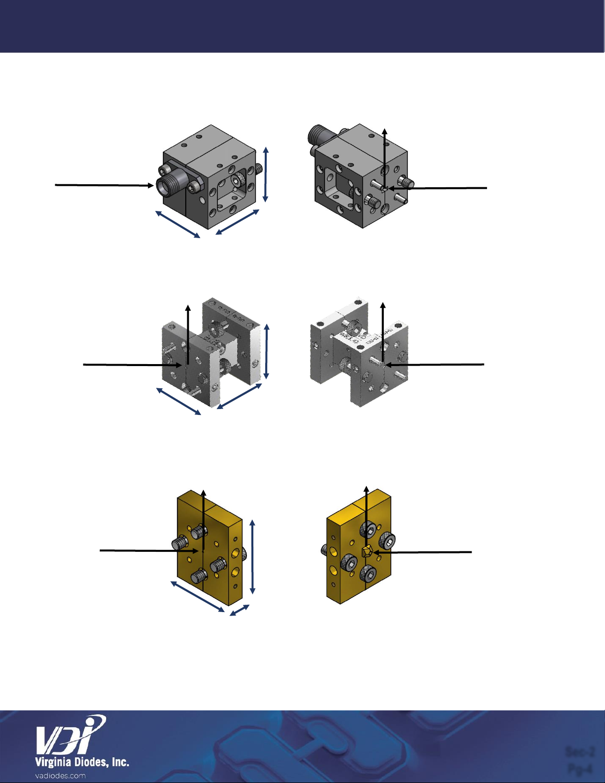
Waveguide Inspection / Test Port Care
•Inspect waveguide flanges for debris prior to making connections.
•Making a connection with metal debris between the waveguide flanges can damage the waveguide interface and prevent
repeatable connections.
•If debris is present, clean the flange with pre-dampened lint free wipes or swabs (e.g. TexWipe TX1065). If these are not
available, lint free cloths lightly dampened with ethanol may be used (e.g. TexWipe TX604).
•When device is not in use, cover appropriate waveguide flanges with provided dust cap or protective waveguide tape.
•Waveguide screws should be torqued between 20-50 cNm; greater values can damage the interface.
•Use a torque of 90 cNm when making coaxial connections. Avoid sharp bends in cables.
General Operating Practices and Recommendations
•This manual applies to products shipping after March 24, 2020.
•Check with VDI before any use is attempted beyond those described in this manual, including uses that may exceed
limitations stated here or commonly accepted standards of practice.
Required Operating Procedures
•DO NOT exceed maximum input power limits (see product datasheet).
•When attaching the tripler’s output port to an active device, the input return loss of the active device must not exceed 0dB.
Failure to follow these required operating procedures may damage or destroy the device and will void the product warranty.
General Overview, Safety and Operational Guidelines
Sec-1
Pg-3

© 2020 Virginia Diodes, Inc.—All Rights Reserved—Rev: 3 April 2020
Low Frequency Broadband Frequency Triplers (WR-15 to WR-6.5)
These triplers will have a coaxial input port and a rectangular waveguide output port, with the exception of the WR-6.5 tripler, which has rectangular waveguide
input and output ports. The drawing and corresponding dimensions are for a typical WR-12 frequency tripler. Other triplers (WR-15 to WR-6.5) will have similar
configuration and dimensions.
Middle Frequency Broadband Frequency Triplers (WR-5.1 to WR-1.5)
These triplers will have rectangular waveguide input and output ports. The drawing and corresponding dimensions are for a typical WR-5.1 frequency tripler. Other
triplers (WR-5.1 to WR-1.5) will have similar configuration and dimensions.
High Frequency Broadband Frequency Triplers (WR-1.2 to WR-0.34)
These triplers will have a rectangular waveguide input. The output port will be either a rectangular waveguide or an integrated horn antenna (~25dBi). The drawing
and corresponding dimensions are for a typical WR-0.8 frequency tripler. Other triplers (WR-1.2 to WR-0.34) with the exception of WR-0.65 will have similar
configuration and dimensions. WR-0.65 frequency tripler will be in the compact form factor. See below.
Sec-2
Pg-4
Section
Two
Product Overview
E-Field
E-Field
E-Field
0.90”
0.90”
0.90”
RF Input
0.75”
0.75”
0.80”
RF Input
1.00”
0.80”
0.25”
RF Output
RF Input
RF Output
RF Output
E-Field
E-Field

© 2020 Virginia Diodes, Inc.—All Rights Reserved—Rev: 3 April 2020
Compact High Frequency Broadband Frequency Triplers (WR-1.2 to WR-0.34)
VDI will transition the High Frequency Broadband Triplers to a compact form factor. These triplers will have a rectangular waveguide input and output flange. The
drawing and corresponding dimensions are for a typical WM-164 (WR-0.65) frequency tripler. Currently, only the WM-164 (WR-0.65) frequency tripler is available
in this form factor.
General Operating Procedure
RF input power must be applied to generate RF output power. The RF output frequency is exactly three times the RF input frequency.
E-Field
0.75”
0.75”
0.25”
RF Output
RF Input
E-Field
Product Overview –Continued
Sec-2
Pg-5

© 2020 Virginia Diodes, Inc.—All Rights Reserved—Rev: 3 April 2020
†VDI triplers are warrantied for room temperature operation. VDI can offer an enhanced warranty that extends the standard VDI warranty to cryogenic operation. Contact VDI
for costs associated with the cryogenic warranty option.
††Unwanted harmonic performance assumes appropriate RF input power.
†RF
Flanges with ‘WR’ designation have UG-387/U-M flanges, with the exception of the WR-19, which has a UG-383/U flange.
††Efficiency assumes appropriate RF input power is applied to the device. Reduced efficiency is possible at band edges & upper and lower input power limits. Efficiency is
defined as the RF output power, expressed as a percentage of the RF input power.
*Integrated Diagonal Horn antenna has a gain of ~25dBi specified at the center of the waveguide band. The gain changes as a function of frequency. See VDI Application Note:
VDI Waveguide Feedhorn Specification (VDI-1001) for more information.
**Additional power options may be available upon request. Contact VDI for more information.
Part Number Format
Use “VDI Part Number” in above table with appropriate suffix for the desired input power option.
Example: WR2.2X3HP –VDI Frequency Tripler with output frequency of 325-500 GHz and RF input power range of 15-70mW.
General Specifications for Broadband Frequency Triplers
Description
Specification
Maximum Weight
~0.1 lbs.
Operating Temperature (Typical / Recommended)
25°C / 20-30°C†
Unwanted Harmonics (Typical)
-20dBc††
Product Specifications for Broadband Frequency Triplers
VDI Part
Number
RF Output
Frequency
(GHz)
RF Output
Flange†
RF Input
Frequency
(GHz)
RF
Input
Flange†
Typical
Efficiency
(%)††
Input Power Options
(Input Power Range / Damage Limit)**
WR15X3
50-75
WR-15
16.67-25
2.9mm(f)
3.5
HP (100-500mW / 625mW)
WR12X3
60-90
WR-12
20-30
2.9mm(f)
3.5
HP (75-400mW / 500mW)
WR10X3
75-110
WR-10
25-36.7
2.9mm(f)
3.5
MP (40-220mW / 275mW), HP (60-360mW / 450mW)
WR9.0X3
82-125
WR-9.0
27.3-41.7
2.9mm(f)
3.5
HP (60-250mW / 315mW)
WR8.0X3
90-140
WR-8.0
30-46.7
2.4mm(f)
3
MP (20-100mW, 120mW), HP (40-240mW / 300mW)
WR6.5X3
110-170
WR-6.5
36.7-56.7
WR-19.5
3
S (20-100mW / 120mW), HP (40-200mW / 250mW)
WR5.1X3
140-220
WR-5.1
46.7-73.3
WR-15.3
3
S (10-40mW / 50mW), HP (20-100mW / 120mW)
WR4.3X3
170-260
WR-4.3
56.7-86.7
WR-12.9
3
S (10-40mW / 50mW), HP (20-100mW / 120mW)
WR3.4X3
220-330
WR-3.4
73.3-110
WR-10.2
3
S (5-35mW / 45mW), HP (20-90mW / 110mW),
UHP (30-160mW / 200mW)
WR2.8X3
260-400
WR-2.8
86.7-133.3
WR-8.4
3
S (5-35mW / 45mW), HP (20-90mW / 110mW),
UHP (30-160mW / 200mW)
WR2.2X3
330-500
WR-2.2
110-166.7
WR-6.6
2
S (5-25mW / 30mW), HP (15-70mW / 90mW),
UHP (20-150mW / 180mW)
WR1.9X3
400-600
WR-1.9
133.3-200
WR-5.7
1.5
S (5-25mW / 30mW), HP (15-65mW / 80mW),
UHP (20-140mW / 175mW)
WR1.5X3
500-750
WR-1.5
166.7-250
WR-4.5
1.5
S (5-25mW / 30mW), HP (15-65mW / 80mW)
WR1.2X3
600-900
WR-1.2
200-300
WR-3.6
1
S (5-25mW / 30mW), HP (15-50mW / 60mW)
WR1.0X3
750-1100
WR-1.0
250-366.7
WR-3.0
0.5
S (5-25mW / 30mW), HP (15-50mW / 60mW)
WR0.8X3
900-1400
WR-0.8 Horn*
300-466.7
WR-2.4
0.2
S (5-25mW / 30mW)
WR0.65X3
1100-1700
WR-0.65
366.7-566.7
WR-1.9
0.2
LP (0.5-4.5mW / 5.5mW), S (5-25mW / 30mW)
WR0.51X3
1400-2200
WR-0.51 Horn*
466.7-733.3
WR-1.5
0.1
LP (0.5-3mW / 4mW)
WR0.34X3
2200-3300
WR-0.34 Horn*
733.3-1100
WR-1.0
0.05
LP (0.5-3mW / 4mW)
Product Specifications
Sec-2
Pg-6

© 2020 Virginia Diodes, Inc.—All Rights Reserved—Rev: 3 April 2020
Broadband Frequency Tripler Performance
Typical efficiency data is provided on the following pages for various broadband frequency triplers. Additional data can be found
on the VDI website or may be available upon request ([email protected]m). Measured efficiency data is shipped with each
VDI broadband frequency tripler.
Performance –WR15 and WR10
Appendix
One
0
2
4
6
8
10
50 55 60 65 70 75
Efficiency (%)
Frequency (GHz)
WR15
Efficiency Efficiency (typ.)
0
2
4
6
8
10
75 80 85 90 95 100 105 110
Efficiency (%)
Frequency (GHz)
WR10
Efficiency Efficiency (typ.)
App-1
Pg-8

© 2020 Virginia Diodes, Inc.—All Rights Reserved—Rev: 3 April 2020
App-1
Pg-8
0
2
4
6
8
10
220 230 240 250 260 270 280 290 300 310 320 330
Efficiency (%)
Frequency (GHz)
WR3.4
Efficiency Efficiency (typ.)
0
1
2
3
4
5
6
330 340 350 360 370 380 390 400 410 420 430 440 450 460 470 480 490 500
Efficiency (%)
Frequency (GHz)
WR2.2
Efficiency Efficiency (typ.)
Performance –WR3.4 and WR2.2

© 2020 Virginia Diodes, Inc.—All Rights Reserved—Rev: 3 April 2020
Efficiency vs. RF Input Power
This graph shows measured data for a specific WR-10 frequency tripler at ~90 GHz. As the RF input power is increased, the
efficiency will start to increase until the efficiency achieves a maximum value. Beyond this point, the efficiency reduces as the
tripler begins to saturate.
The general shape of the curve is consistent with all VDI’s broadband frequency triplers. However, the scale depends on the
specific tripler design, the operating frequency and other operating conditions, for example temperature and impedance matching
with the source and load.
Efficiency versus power data can be supplied for all shipped triplers at an additional cost.
Efficiency vs. RF Input Power
0
1
2
3
4
5
6
7
8
9
10
050 100 150 200 250 300 350 400 450
EFficiency (%)
RF Input Power (mW)
WR10X3HP Efficiency vs. RF Input Power
Figure 1: Efficiency vs. RF Input Power
The performance (efficiency vs. RF input power) is shown for a sample WR10X3HP at ~90 GHz.
Appendix
Two
App-2
Pg-9

© 2020 Virginia Diodes, Inc.—All Rights Reserved—Rev: 3 April 2020
The Virginia Diodes staff of engineering and physical science professionals works to continually improve our products. We also
depend upon feedback from colleagues and customers. Ideas to simplify component operations, improve performance or add
capabilities are always welcome.
Contact VDI:
Virginia Diodes, Inc.
Web: http://www.vadiodes.com
Email: Technical@vadiodes.com
Telephone: 434.297.3257
Addendum —Product Updates and Company Contacts
Addendum
Pg-10
This manual suits for next models
16
Table of contents