Vishay P10TR User manual

P10TR
www.vishay.com Vishay Semiconductors
Rev. 1.2, 19-Apr-18 1Document Number: 82794
THIS DOCUMENT IS SUBJECT TO CHANGE WITHOUT NOTICE. THE PRODUCTS DESCRIBED HEREIN AND THIS DOCUMENT
ARE SUBJECT TO SPECIFIC DISCLAIMERS, SET FORTH AT www.vishay.com/doc?91000
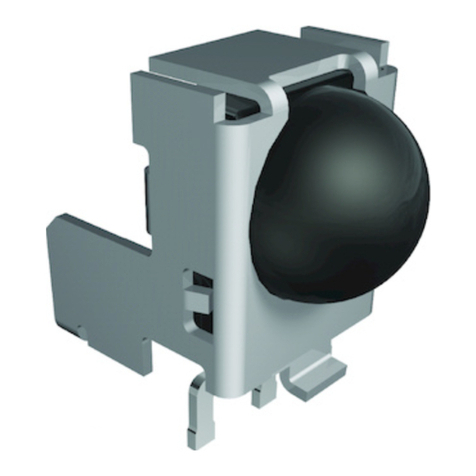
Side View Pin-In-Paste Holder:
D = 9.0 mm, H = 8.05 mm, W = 6.2 mm, X = 5.15 mm
FEATURES
• Material categorization:
for definitions of compliance please see
www.vishay.com/doc?99912
AVAILABLE FOR
•TSOP33...
•TSOP53...
•TSOP13...
•TSOP93...
• TSSP53...
MECHANICAL DIMENSIONS in millimeters
22940
2294
0
“H”
“X”
“W”
“D”
20248
NAME LENS AXIS (X) VIEW TYPE HEIGHT (H) WIDTH (W) DEPTH (D)
P10TR 5.15 Side Holder 8.05 6.2 9.0
(3.9)
6.2
3.6
1.4
(5.15)
0.3 ± 0.1
0
0.85
1.5
3.3
3.8
8.05 ± 0.2
0
0.5
3.6
6.6
9
Ø 0.95
0.65 ± 0.2
(3x)
(3x)
5.08
2.54
Drawing-No.: 6.550-5351.01-4
Issue: 3, 18.04.18
Proposed pad layout
from component side
(for reference only)
Technical drawings
according to DIN
specification.
Not indicated tolerances± 0.3
123
Marking area
(R2.5)
(R2.5)
1.7 ± 0.2
0.9 ± 0.2
1 ± 0.2
4
3.25 3.25
1.2
1.2
1.2
1.2
5.1 ± 0.4
1
1.2
2.1
0.6 ± 0.2
0.6 ± 0.1
(3.7)
(3.8)
(3)
2.54 ± 0.2 nom.
5.08 ± 0.2 nom.

P10TR
www.vishay.com Vishay Semiconductors
Rev. 1.2, 19-Apr-18 2Document Number: 82794
THIS DOCUMENT IS SUBJECT TO CHANGE WITHOUT NOTICE. THE PRODUCTS DESCRIBED HEREIN AND THIS DOCUMENT
ARE SUBJECT TO SPECIFIC DISCLAIMERS, SET FORTH AT www.vishay.com/doc?91000
TAPING VERSION TSOP..TR DIMENSIONS in millimeters
ORDERING INFORMATION
Note
• d = “digit”, please consult the list of available series on the previous page to create a valid part number
Example: TSOP53438P10TR
PACKAGING QUANTITY
• 500 pieces per reel
TSOP ddd dd P10 TR
Product series
(2 or 3 digits)
Frequency Holder type Taping
AA
B
B
Drawing-No.: MM-200-232.01-4_Z
Issue A: 25.04.17
Direction of feed
(24)
(12)
(2)
(4)
(Ø 1.55)
(Ø 1.5)
(11.5)
(1.75)
A-A (2:1)
(10.8)
(8.4)
1.9 ref.
(3.53)
(7.55)
B-B (2:1)
6.23 ref.
(6.65)
(0.5)
Technical drawings
according to DIN
specication.

P10TR
www.vishay.com Vishay Semiconductors
Rev. 1.2, 19-Apr-18 3Document Number: 82794
THIS DOCUMENT IS SUBJECT TO CHANGE WITHOUT NOTICE. THE PRODUCTS DESCRIBED HEREIN AND THIS DOCUMENT
ARE SUBJECT TO SPECIFIC DISCLAIMERS, SET FORTH AT www.vishay.com/doc?91000
REEL DIMENSIONS in millimeters
LEADER AND TRAILER DIMENSIONS in millimeters
COVER TAPE PEEL STRENGTH
According to DIN EN 60286-3
0.1 N to 1.3 N
300 ± 10 mm/min.
165° to 180° peel angle
Drawing-No.: 9.800-5052.V3-4
Issue: 1; 17.12.02
Form of the leave open of the wheel issupplier specic.
Dimensionsaccording to IEC EN 60 286-3
Tape width: 24
Technical drawing
according to DIN
specications
Reel hub 2:1
Ø 20.2 min.
1.5 min.
Ø 12.8 min.
Ø 60 min.
24.4
+3
-0
Ø 330
+0
-4
Trailer Leader
no devices
min. 200 min. 400
StartEnd
devices
96 11818
no devices

P10TR
www.vishay.com Vishay Semiconductors
Rev. 1.2, 19-Apr-18 4Document Number: 82794
THIS DOCUMENT IS SUBJECT TO CHANGE WITHOUT NOTICE. THE PRODUCTS DESCRIBED HEREIN AND THIS DOCUMENT
ARE SUBJECT TO SPECIFIC DISCLAIMERS, SET FORTH AT www.vishay.com/doc?91000
ASSEMBLY INSTRUCTIONS
Reflow Soldering
• Reflow soldering must be done within 72 h while stored
under a max. temperature of 30 °C, 60 % RH after
opening the dry pack envelope
• Set the furnace temperatures for pre-heating and heating
in accordance with the reflow temperature profile as
shown in the diagram. Exercise extreme care to keep the
maximum temperature below 260 °C. The temperature
shown in the profile means the temperature at the device
surface. Since there is a temperature difference between
the component and the circuit board, it should be verified
that the temperature of the device is accurately being
measured
• Handling after reflow should be done only after the work
surface has been cooled off
Manual Soldering
• Use a soldering iron of 25 W or less. Adjust the
temperature of the soldering iron below 300 °C
• Finish soldering within 3 s
• Handle products only after the temperature has cooled
off
VISHAY LEAD (Pb)-FREE REFLOW SOLDER PROFILE
LABEL
Standard bar code labels for finished goods
The standard bar code labels are product labels and used for identification of goods. The finished goods are packed in final
packing area. The standard packing units are labeled with standard bar code labels before transported as finished goods to
warehouses. The labels are on each packing unit and contain Vishay Semiconductor GmbH specific data.
max. 120 s max. 100 s
max. 20 s
Max. ramp up 3 °C/s
max. 260 °C
10
100
1000
10000
0
50
100
250
300
0 300
Axis Title
2nd line
Temperature (°C)
Time (s)
25020015010050
200
150
245 °C
217 °C
240 °C
255 °C
Max. ramp down 6 °C/s
Max. 2 cycles allowed
19800

P10TR
www.vishay.com Vishay Semiconductors
Rev. 1.2, 19-Apr-18 5Document Number: 82794
THIS DOCUMENT IS SUBJECT TO CHANGE WITHOUT NOTICE. THE PRODUCTS DESCRIBED HEREIN AND THIS DOCUMENT
ARE SUBJECT TO SPECIFIC DISCLAIMERS, SET FORTH AT www.vishay.com/doc?91000
DRY PACKING
The reel is packed in an anti-humidity bag to protect the
devices from absorbing moisture during transportation and
storage.
FINAL PACKING
The sealed reel is packed into a cardboard box. A secondary
cardboard box is used for shipping purposes.
VISHAY SEMICONDUCTOR GmbH STANDARD BAR CODE PRODUCT LABEL (finished goods)
PLAIN WRITING ABBREVIATION LENGTH
Item-description - 18
Item-number INO 8
Selection-code SEL 3
LOT-/serial-number BATCH 10
Data-code COD 3 (YWW)
Plant-code PTC 2
Quantity QTY 8
Accepted by ACC -
Packed by PCK -
Mixed code indicator MIXED CODE -
Origin xxxxxxx+ Company logo
LONG BAR CODE TOP TYPE LENGTH
Item-number N 8
Plant-code N 2
Sequence-number X 3
Quantity N 8
Total length - 21
SHORT BAR CODE BOTTOM TYPE LENGTH
Selection-code X 3
Data-code N 3
Batch-number X 10
Filter - 1
Total length - 17
Aluminum bag
Label
Reel
15973

P10TR
www.vishay.com Vishay Semiconductors
Rev. 1.2, 19-Apr-18 6Document Number: 82794
THIS DOCUMENT IS SUBJECT TO CHANGE WITHOUT NOTICE. THE PRODUCTS DESCRIBED HEREIN AND THIS DOCUMENT
ARE SUBJECT TO SPECIFIC DISCLAIMERS, SET FORTH AT www.vishay.com/doc?91000
RECOMMENDED METHOD OF STORAGE
Dry box storage is recommended as soon as the aluminum
bag has been opened to prevent moisture absorption. The
following conditions should be observed, if dry boxes are
not available:
• Storage temperature 10 °C to 30 °C
• Storage humidity ≤60 % RH max.
After more than 72 h under these conditions moisture
content will be too high for reflow soldering.
In case of moisture absorption, the devices will recover to
the former condition by drying under the following condition:
192 h at 40 °C + 5 °C / - 0 °C and < 5 % RH (dry air /
nitrogen) or
96 h at 60 °C + 5 °C and < 5 % RH for all device containers
or
24 h at 125 °C + 5 °C not suitable for reel or tubes.
An EIA JEDEC®standard J-STD-020 level 4 label is included
on all dry bags.
EIA JEDEC standard J-STD-020 level 4 label is included
on all dry bags
ESD PRECAUTION
Proper storage and handling procedures should be followed
to prevent ESD damage to the devices especially when they
are removed from the antistatic shielding bag. Electrostatic
sensitive devices warning labels are on the packaging.
VISHAY SEMICONDUCTORS STANDARD
BAR CODE LABELS
The Vishay Semiconductors standard bar code labels are
printed at final packing areas. The labels are on each
packing unit and contain Vishay Semiconductors specific
data.
CAUTION
This bag contains
MOISTURE-SENSITIVE DEVICES
1. Shelf life in sealed bag: 12 months at < 40 °C and < 90 % relative
humidity (RH)
2. After this bag is opened, devices that will be subjected to soldering
reflow or equivalent processing (peak package body temp. 260 °C)
must be
2a. Mounted within 72 hours at factory condition of < 30 °C/60 % RH or
2b. Stored at < 5 % RH
3. Devices require baking befor mounting if:
Humidity Indicator Card is > 10 % when read at 23 °C ± 5 °C or
2a. or 2b. are not met.
4. If baking is required, devices may be baked for:
192 hours at 40 °C + 5 °C/- 0 °C and < 5 % RH (dry air/nitrogen) or
96 hours at 60 °C ± 5 °C and < 5 % RH for all device containers or
24 hours at 125 °C ± 5 °C not suitable for reels or tubes
Bag Seal Date:
(If blank, see barcode label)
Note: Level and body temperature defined by EIA JEDEC Standard J-STD-020
4
LEVEL
22522
22645
Table of contents
Other Vishay Control Unit manuals

Vishay
Vishay TSSP57038 User manual

Vishay
Vishay G4-PM User manual

Vishay
Vishay TSOP37 TT1 Series User manual

Vishay
Vishay P16TR User manual

Vishay
Vishay TSSP57038 User manual

Vishay
Vishay TSOP573 Series User manual

Vishay
Vishay TSSP570 H Series User manual

Vishay
Vishay TSOP62 Series User manual

Vishay
Vishay TSOP64 Series User manual
Popular Control Unit manuals by other brands

UTC Fire and Security
UTC Fire and Security interlogix VT1101M Installation & operation instructions

Woodward
Woodward easYgen-1000 Applications manual

Eclipse
Eclipse 200 LT Series instruction manual

VeEX
VeEX RXT-6400 user manual

JETStream
JETStream MAGJET X40 Product instructions

CREVIS
CREVIS GT-5352 user manual