Smarteh LPC-2.CX1 User manual

USER MANUAL
Longo programmable controller
LPC-2.CX1
Communication module
Version 2
SMARTEH d.o.o. / Poljubinj 114 / 5220 Tolmin / Slovenia / Tel.: +3 6(0)5 3 44 00 / e-mail: info@smarteh.si / www.smarteh.si

Longo programmable controller LPC-2.CX1
Written by SMART H d.o.o.
Copyright © 2023, SMART H d.o.o.
User Manual
Document Version: 2
March, 2023
i

Longo programmable controller LPC-2.CX1
STANDARDS AND PROVISIONS: Standards, recommendations,
regulations and provisions of the country in which the devices will
operate, must be considered while planning and setting up electrical
devices. Work on 100 .. 240 V AC network is allowed for authorized
personnel only.
DANG R WARNINGS: Devices or modules must be protected from
moisture, dirt and damage during transport, storing and operation.
WARRANTY CONDITIONS: For all modules LONGO LPC-2 – if no
modifications are performed upon and are correctly connected by
authorized personnel – in consideration of maximum allowed
connecting power, warranty of 24 months is valid from the date of
sale to the end buyer, but not more than 36 months after delivery
from Smarteh. In case of claims within warranty time, which are based
on material malfunctions the producer offers free replacement. The
method of return of malfunctioned module, together with description,
can be arranged with our authorized representative. Warranty does
not include damage due to transport or because of unconsidered
corresponding regulations of the country, where the module is
installed.
This device must be connected properly by the provided connection
scheme in this manual. Misconnections may result in device damage,
fire or personal injury.
Hazardous voltage in the device can cause electric shock and may
result in personal injury or death.
N V R S RVIC THIS PRODUCT YOURS LF!
This device must not be installed in the systems critical for life (e.g.
medical devices, aircrafts, etc.).
If the device is used in a manner not specified by the manufacturer,
the degree of protection provided by the equipment may be impaired.
Waste electrical and electronic equipment (W ) must be collected
separately!
LONGO LPC-2 complies to the following standards:
•MC: N 61000-6-3:2007 + A1:2011, N 61000-6-1:2007, N 61000-
3-2:2006 + A1:2009 + A2: 2009, N 61000-3-3:2013
•LVD: I C 61010-1:2010 (3rd d.), I C 61010-2-201:2013 (1st d.)
Smarteh d.o.o. operates a policy of continuous development.
Therefore we reserve the right to make changes and improvements to
any of the products described in this manual without any prior notice.
MANUFACTUR R:
SMART H d.o.o.
Poljubinj 114
5220 Tolmin
Slovenia
ii

Longo programmable controller LPC-2.CX1
Longo programmable controller LPC-2.CX1
1 ABBR VIATIONS................................................................................1
2 D SCRIPTION...................................................................................2
3 F ATUR S.......................................................................................3
4 OP RATION.....................................................................................4
4.1 SmartehID Parameters...............................................................4
4.2 Modbus RTU and SmartehID Parameters – Modbus RTU mode.................5
4.3 Modbus RTU and SmartehID Parameters – Universal mode...................16
4.4 Sound module command format...................................................19
4.5 Sound module commands list.......................................................19
5 INSTALLATION................................................................................23
5.1 Connection scheme..................................................................23
5.2 Mounting instructions................................................................25
6 T CHNICAL SP CIFICATIONS................................................................27
7 MODUL LAB LING...........................................................................28
8 CHANG S .....................................................................................29
9 NOT S..........................................................................................30
iii

Longo programmable controller LPC-2.CX1
1 A REVIATIONS
DC Direct Current
RX Receive
TX Transmit
UART Universal Asynchronous Receiver-Transmitter
1

Longo programmable controller LPC-2.CX1
2 DESCRIPTION
LPC-2.CX1 is a communication module with a port for RS-485 communication. It's main feature is
being a gateway for Modbus RTU or other UART protocols, exchanging data with the main module,
where all of data is being interpreted. It also equipped with a MP3 player and an audio amplifier for
an external speaker connection.
LPC-2.CX1 is controlled and powered from the main module (e.g. LPC-2.MU1, LPC-2.MC9, ...) via
Right internal bus.
2

Longo programmable controller LPC-2.CX1
3 FEATURES
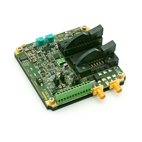
Figure 1: LPC-2.CX1 module
Table 1: Technical data
RS-485 master port for Modbus RTU or other UART protocols
MP3 player
10 W audio amplifier
Internal 4 MB Flash
USB for external memory or internal flash loading
Signal L Ds
Supplied from main module
Small dimensions and standard DIN N50022-35 rail mounting
3

Longo programmable controller LPC-2.CX1
4 OPERATION
LPC-2.CX1 module can be controlled from main PLC module (e.g. LPC-2.MC9). Module parameters
can be read or written via Smarteh ID software. To use the LPC-2.CX1 module in your Smarteh ID
programming software configuration, you must select the universal module LPC-2.Cxx.
LPC-2.CX1 module can also be controlled by the Modbus RTU Slave main module (e.g. LPC-2.MU1).
4.1 SmartehIDE Parameters
Input
Receive data [i_Rx_Data_{1..298}]: Generic receive data.
Type: USINT
Raw to engineering data: 0 .. 255 →0 .. 255
Output
Transmit data [o_Tx_Data _{1..298}]: Generic transmit data.
Type: USINT
Raw to engineering data: 0 .. 255 →0 .. 255
4

Longo programmable controller LPC-2.CX1
4.2 Modbus RTU and SmartehIDE Parameters – Modbus RTU mode
By specifying the first parameter Protocol type, Parameter number 1, Modbus RTU holding register
93 High byte (93.H), determine the type of communication on the RS-485 communication port.
Based on this parameter, the content of further communication parameters is determined. The
parameters are described in the tables below.
If protocol type Modbus RTU master driver is selected use the tables in this chapter numbered
from 2 to 21.
In the first column named Reg. are Modbus RTU registers. These are used for controlling LPC-2.CX1
module from the Modbus RTU Slave main module (e.g. LPC-2.MU1).
In second column named Par. there are SmartehID parameter indexes. These are used for
controlling LPC-2.CX1 module from the main module (e.g. LPC-2.MC9).
Table 2: Communication settings, Modbus RTU mode
4xxxx, Modbus RTU Holding registers
SmartehIDE output parameters
Reg. Par. Name Description Raw → Engineering data
93.L11 Protocol_Type Communication protocol type
0 Universal UART→
1 Modbus RTU master →
driver
93.H22 Protocol_Option Protocol option Not used
94.L 3 UART_Speed Selector of baudrate
0 300→
1 600→
2 1200→
3 2400→
4 4800→
5 9600→
6 19200→
7 38400→
8 57600→
9 115200→
other 19200→
94.H 4 UART_Parity Selector of parity
0 No parity bit→
1 Odd→
2 ven→
other No parity bit→
95.L 5 UART_Databits Number of data bits
5 5 bits→
6 6 bits →
7 7 bits→
8 8 bits→
other 8 bits→
95.H 6 UART_Stopbits Number of stop bits
0 1 bit→
1 1 bit→
2 2 bits→
other 2 bits→
1 Low byte
2 High byte
5

Longo programmable controller LPC-2.CX1
Table 2: Communication settings, Modbus RTU mode
4xxxx, Modbus RTU Holding registers
SmartehIDE output parameters
96 7,8 Rx_TLG_Timeout Time delay between Modbus
telegrams
0 No timeout→
1 .. 65535 1 .. 65535 ms→
97 9,10 Rx_Data_Timeout Timeout waiting for answer for
Modbus telegrams
0 No timeout→
1 .. 65535 1 .. 65535 ms→
98 11,12 Not used Not used
99 13,14 Tx_SoundCard_SendC
ommand
Transmit sound card data only
when counter changes 1 .. 65535 1 .. 65535→
100.L 15 Tx_SendCommand Transmit data only when
counter changes
0 Continuous →
communication
255 Communication →
stopped
1 .. 254 1 .. 254→
Table 3: Communication feedback, Modbus RTU mode
3xxxx, Modbus RTU input registers
SmartehIDE input parameters
Reg. Par. Name Description Raw → Engineering data
103.L 1 Protocol_Type_FBD Communication protocol type
feedback
0 Universal UART→
1 Modbus RTU master →
driver
103.H 2 I2C_Session_Counter
It changes after each session,
when data in module updates. It
updates every cca.100 ms.
0 .. 255 0 .. 255→
104.L 3 Tx_Counter It increments when new Modbus
or UART data were transmitted 0 .. 255 0 .. 255→
104.H
105.L 4,5 Tx_ rror_Counter Number of failed communication
telegrams 0 .. 65535 0 .. 65535→
105.H 6 Modbus_Status Status of last Modbus transaction
0 OK→
1 rror→
3 Timeout →
106.L 7 Modbus_ rror_Code Last Modbus transaction error
code
0 None→
1 Illegal function→
2 Illegal data address→
3 Illegal data value→
4 Slave device failure→
5 Acknowledge→
6 Slave busy→
7 Not acknowledge→
8 Memory parity error→
10 Gateway path →
unavailable
11 Gateway target →
failed
106.H
107.L 8,9 SoundCardResponse_
Counter
Increments when sound card
response is received 0 .. 65535 0 .. 65535→
6

Longo programmable controller LPC-2.CX1
Table 4: Tx uffer, M S1 Head, Modbus RTU mode
4xxxx, Modbus RTU Holding registers
SmartehIDE output parameters
Reg. Par. Name Description Raw → Engineering data
101.L 17 Slave_Address Modbus RTU port slave address
0 Not active→
1 .. 255 SlaveID1 .. SlaveID →
255
101.H 18 Modbus_Function Modbus function codes
1 Read Coils→
2 Read Discrete inputs→
3 Read Holding registers→
4 Read Input register→
15 Write Multiple Coils→
16 Write Holding registers→
102 19,20 Register_Address Modbus Slave register address 0 .. 65535 0 .. 65535→
103.L 21 Data_Length Number of words/bits. Depends
on selected function. 0 .. 255 0 .. 255→
103.H 22 Not used Not used
104 23,24 Buffer_Start
Data buffer start. Write
commands are related to Tx
buffer, Read commands to Rx
buffer.
81 .. 286 81 .. 286 (Tx)→
41 .. 286 41 .. 286 (Rx)→
Table 5: Tx uffer, M S2 Head, Modbus RTU mode
4xxxx, Modbus RTU Holding registers
SmartehIDE output parameters
Reg. Par. Name Description Raw → Engineering data
105.L 25 Slave_Address Modbus RTU port slave address
0 Not active→
1 .. 255 SlaveID1 .. SlaveID →
255
105.H 26 Modbus_Function Modbus function codes
1 Read Coils→
2 Read Discrete inputs→
3 Read Holding registers→
4 Read Input register→
15 Write Multiple Coils→
16 Write Holding registers→
106 27,28 Register_Address Modbus Slave register address 0 .. 65535 0 .. 65535→
107.L 29 Data_Length Number of words/bits. Depends
on selected function. 0 .. 255 0 .. 255→
107.H 30 Not used Not used
108 31,32 Buffer_Start
Data buffer start. Write
commands are related to Tx
buffer, Read commands to Rx
buffer.
81 .. 286 81 .. 286 (Tx)→
41 .. 286 41 .. 286 (Rx)→
7

Longo programmable controller LPC-2.CX1
Table 6: Tx uffer, M S3 Head, Modbus RTU mode
4xxxx, Modbus RTU Holding registers
SmartehIDE output parameters
Reg. Par. Name Description Raw → Engineering data
109.L 33 Slave_Address Modbus RTU port slave address
0 Not active→
1 .. 255 SlaveID1 .. SlaveID →
255
109.H 34 Modbus_Function Modbus function codes
1 Read Coils→
2 Read Discrete inputs→
3 Read Holding registers→
4 Read Input register→
15 Write Multiple Coils→
16 Write Holding registers→
110 35,36 Register_Address Modbus Slave register address 0 .. 65535 0 .. 65535→
111.L 37 Data_Length Number of words/bits. Depends
on selected function. 0 .. 255 0 .. 255→
111.H 38 Not used Not used
112 39,40 Buffer_Start
Data buffer start. Write
commands are related to Tx
buffer, Read commands to Rx
buffer.
81 .. 286 81 .. 286 (Tx)→
41 .. 286 41 .. 286 (Rx)→
Table 7: Tx uffer, M S4 Head, Modbus RTU mode
4xxxx, Modbus RTU Holding registers
SmartehIDE output parameters
Reg. Par. Name Description Raw → Engineering data
113.L 41 Slave_Address Modbus RTU port slave address
0 Not active→
1 .. 255 SlaveID1 .. SlaveID →
255
113.H 42 Modbus_Function Modbus function codes
1 Read Coils→
2 Read Discrete inputs→
3 Read Holding registers→
4 Read Input register→
15 Write Multiple Coils→
16 Write Holding registers→
114 43,44 Register_Address Modbus Slave register address 0 .. 65535 0 .. 65535→
115.L 45 Data_Length Number of words/bits. Depends
on selected function. 0 .. 255 0 .. 255→
115.H 46 Not used Not used
116 47,48 Buffer_Start
Data buffer start. Write
commands are related to Tx
buffer, Read commands to Rx
buffer.
81 .. 286 81 .. 286 (Tx)→
41 .. 286 41 .. 286 (Rx)→
8

Longo programmable controller LPC-2.CX1
Table 8: Tx uffer, M S5 Head, Modbus RTU mode
4xxxx, Modbus RTU Holding registers
SmartehIDE output parameters
Reg. Par. Name Description Raw → Engineering data
117.L 49 Slave_Address Modbus RTU port slave address
0 Not active→
1 .. 255 SlaveID1 .. SlaveID →
255
117.H 50 Modbus_Function Modbus function codes
1 Read Coils→
2 Read Discrete inputs→
3 Read Holding registers→
4 Read Input register→
15 Write Multiple Coils→
16 Write Holding registers→
118 51,52 Register_Address Modbus Slave register address 0 .. 65535 0 .. 65535→
119.L 53 Data_Length Number of words/bits. Depends
on selected function. 0 .. 255 0 .. 255→
119.H 54 Not used Not used
120 55,56 Buffer_Start
Data buffer start. Write
commands are related to Tx
buffer, Read commands to Rx
buffer.
81 .. 286 81 .. 286 (Tx)→
41 .. 286 41 .. 286 (Rx)→
Table 9: Tx uffer, M S6 Head, Modbus RTU mode
4xxxx, Modbus RTU Holding registers
SmartehIDE output parameters
Reg. Par. Name Description Raw → Engineering data
121.L 57 Slave_Address Modbus RTU port slave address
0 Not active→
1 .. 255 SlaveID1 .. SlaveID →
255
121.H 58 Modbus_Function Modbus function codes
1 Read Coils→
2 Read Discrete inputs→
3 Read Holding registers→
4 Read Input register→
15 Write Multiple Coils→
16 Write Holding registers→
122 59,60 Register_Address Modbus Slave register address 0 .. 65535 0 .. 65535→
123.L 61 Data_Length Number of words/bits. Depends
on selected function. 0 .. 255 0 .. 255→
123.H 62 Not used Not used
124 63,64 Buffer_Start
Data buffer start. Write
commands are related to Tx
buffer, Read commands to Rx
buffer.
81 .. 286 81 .. 286 (Tx)→
41 .. 286 41 .. 286 (Rx)→
9

Longo programmable controller LPC-2.CX1
Table 10: Tx uffer, M S7 Head, Modbus RTU mode
4xxxx, Modbus RTU Holding registers,
SmartehIDE output parameters
Reg. Par. Name Description Raw → Engineering data
125.L 65 Slave_Address Modbus RTU port slave address
0 Not active→
1 .. 255 SlaveID1 .. SlaveID →
255
125.H 66 Modbus_Function Modbus function codes
1 Read Coils→
2 Read Discrete inputs→
3 Read Holding registers→
4 Read Input register→
15 Write Multiple Coils→
16 Write Holding registers→
126 67,68 Register_Address Modbus Slave register address 0 .. 65535 0 .. 65535→
127.L 69 Data_Length Number of words/bits. Depends
on selected function. 0 .. 255 0 .. 255→
127.H 70 Not used Not used
128 71,72 Buffer_Start
Data buffer start. Write
commands are related to Tx
buffer, Read commands to Rx
buffer.
81 .. 286 81 .. 286 (Tx)→
41 .. 286 41 .. 286 (Rx)→
Table 11: Tx uffer, M S8 Head, Modbus RTU mode
4xxxx, Modbus RTU Holding registers
SmartehIDE output parameters
Reg. Par. Name Description Raw → Engineering data
129.L 73 Slave_Address Modbus RTU port slave address
0 Not active→
1 .. 255 SlaveID1 .. SlaveID →
255
129.H 74 Modbus_Function Modbus function codes
1 Read Coils→
2 Read Discrete inputs→
3 Read Holding registers→
4 Read Input register→
15 Write Multiple Coils→
16 Write Holding registers→
130 75,76 Register_Address Modbus Slave register address 0 .. 65535 0 .. 65535→
131.L 77 Data_Length Number of words/bits. Depends
on selected function. 0 .. 255 0 .. 255→
131.H 78 Not used Not used
132 79,80 Buffer_Start
Data buffer start. Write
commands are related to Tx
buffer, Read commands to Rx
buffer.
81 .. 286 81 .. 286 (Tx)→
41 .. 286 41 .. 286 (Rx)→
10

Longo programmable controller LPC-2.CX1
Table 12: Tx uffer, Data, Modbus RTU mode
4xxxx, Holding registers
SmartehIDE output parameters
Reg. Par. Name Description Raw → Engineering data
133.L 81 Tx_Modbus_Buffer_Start Start of transmit Modbus
buffer 0 .. 65535 0 .. 65535→
... ...
235.H 286 Tx_Modbus_Buffer_ nd nd of transmit Modbus
buffer 0 .. 65535 0 .. 65535→
236.L 287 Tx_Sound_Buffer_Start Start of transmit sound
card Modbus buffer 0 .. 65535 0 .. 65535→
... ...
241.H 298 Tx_Sound_Buffer_ nd nd of transmit sound card
Modbus buffer 0 .. 65535 0 .. 65535→
Table 13: Rx uffer, M S1 Head, Modbus RTU mode
3xxxx, Modbus RTU Input registers
SmartehIDE input parameters
Reg. Par. Name Description Raw → Engineering data
109.L 13 Rx_Counter Number of successful
transactions 0 .. 255 0 .. 255→
109.H 14 Rx_ rror_Counter Number of failed transactions 0 .. 255 0 .. 255→
110.L 15 Modbus_Status Status of last Modbus
transaction
0 OK→
1 Modbus error→
3 Timeout→
4 Wrong parameters→
110.H 16 Modbus_ rror_Code Last Modbus transaction error
code
0 None→
1 Illegal function→
2 Illegal data address→
3 Illegal data value→
4 Slave device failure→
5 Acknowledge→
6 Slave busy→
7 Not acknowledge→
8 Memory parity error→
10 Gateway path →
unavailable
11 Gateway target failed→
11

Longo programmable controller LPC-2.CX1
Table 14: Rx uffer, M S2 Head, Modbus RTU mode
3xxxx, Modbus RTU Input registers
SmartehIDE input parameters
Reg. Par. Name Description Raw → Engineering data
111.L 17 Rx_Counter Number of successful
transactions 0 .. 255 0 .. 255→
111.H 18 Rx_ rror_Counter Number of failed transactions 0 .. 255 0 .. 255→
112.L 19 Modbus_Status Status of last Modbus
transaction
0 OK→
1 Modbus error→
3 Timeout→
4 Wrong parameters→
112.H 20 Modbus_ rror_Code Last Modbus transaction error
code
0 None→
1 Illegal function→
2 Illegal data address→
3 Illegal data value→
4 Slave device failure→
5 Acknowledge→
6 Slave busy→
7 Not acknowledge→
8 Memory parity error→
10 Gateway path →
unavailable
11 Gateway target failed→
Table 15: Rx uffer, M S3 Head, Modbus RTU mode
3xxxx, Modbus RTU Input registers
SmartehIDE input parameters
Reg. Par. Name Description Raw → Engineering data
113.L 21 Rx_Counter Number of successful
transactions 0 .. 255 0 .. 255→
113.H 22 Rx_ rror_Counter Number of failed transactions 0 .. 255 0 .. 255→
114.L 23 Modbus_Status Status of last Modbus
transaction
0 OK→
1 Modbus error→
3 Timeout→
4 Wrong parameters→
114.H 24 Modbus_ rror_Code Last Modbus transaction error
code
0 None→
1 Illegal function→
2 Illegal data address→
3 Illegal data value→
4 Slave device failure→
5 Acknowledge→
6 Slave busy→
7 Not acknowledge→
8 Memory parity error→
10 Gateway path →
unavailable
11 Gateway target failed→
12

Longo programmable controller LPC-2.CX1
Table 16: Rx uffer, M S4 Head, Modbus RTU mode
4xxxx, Modbus RTU Input registers
SmartehIDE input parameters
Reg. Par. Name Description Raw → Engineering data
115.L 25 Rx_Counter Number of successful
transactions 0 .. 255 0 .. 255→
115.H 26 Rx_ rror_Counter Number of failed transactions 0 .. 255 0 .. 255→
116.L 27 Modbus_Status Status of last Modbus
transaction
0 OK→
1 Modbus error→
3 Timeout→
4 Wrong parameters→
116.H 28 Modbus_ rror_Code Last Modbus transaction error
code
0 None→
1 Illegal function→
2 Illegal data address→
3 Illegal data value→
4 Slave device failure→
5 Acknowledge→
6 Slave busy→
7 Not acknowledge→
8 Memory parity error→
10 Gateway path →
unavailable
11 Gateway target failed→
Table 17: Rx uffer, M S5 Head, Modbus RTU mode
3xxxx, Modbus RTU Input registers
SmartehIDE input parameters
Reg. Par. Name Description Raw → Engineering data
117.L 29 Rx_Counter Number of successful
transactions 0 .. 255 0 .. 255→
117.H 30 Rx_ rror_Counter Number of failed transactions 0 .. 255 0 .. 255→
118.L 31 Modbus_Status Status of last Modbus
transaction
0 OK→
1 Modbus error→
3 Timeout→
4 Wrong parameters→
118.H 32 Modbus_ rror_Code Last Modbus transaction error
code
0 None→
1 Illegal function→
2 Illegal data address→
3 Illegal data value→
4 Slave device failure→
5 Acknowledge→
6 Slave busy→
7 Not acknowledge→
8 Memory parity error→
10 Gateway path →
unavailable
11 Gateway target failed→
13

Longo programmable controller LPC-2.CX1
Table 18: Rx uffer, M S6 Head, Modbus RTU mode
3xxxx, Modbus RTU Input registers,
SmartehIDE input parameters
Reg. Par. Name Description Raw → Engineering data
119.L 33 Rx_Counter Number of successful
transactions 0 .. 255 0 .. 255→
119.H 34 Rx_ rror_Counter Number of failed transactions 0 .. 255 0 .. 255→
120.L 35 Modbus_Status Status of last Modbus
transaction
0 OK→
1 Modbus error→
3 Timeout→
4 Wrong parameters→
120.H 36 Modbus_ rror_Code Last Modbus transaction error
code
0 None→
1 Illegal function→
2 Illegal data address→
3 Illegal data value→
4 Slave device failure→
5 Acknowledge→
6 Slave busy→
7 Not acknowledge→
8 Memory parity error→
10 Gateway path →
unavailable
11 Gateway target failed→
Table 19: Rx uffer, M S7 Head, Modbus RTU mode
3xxxx, Modbus RTU Input registers
SmartehIDE input parameters
Reg. Par. Name Description Raw → Engineering data
121.L 37 Rx_Counter Number of successful
transactions 0 .. 255 0 .. 255→
121.H 38 Rx_ rror_Counter Number of failed transactions 0 .. 255 0 .. 255→
122.L 39 Modbus_Status Status of last Modbus
transaction
0 OK→
1 Modbus error→
3 Timeout→
4 Wrong parameters→
122.H 40 Modbus_ rror_Code Last Modbus transaction error
code
0 None→
1 Illegal function→
2 Illegal data address→
3 Illegal data value→
4 Slave device failure→
5 Acknowledge→
6 Slave busy→
7 Not acknowledge→
8 Memory parity error→
10 Gateway path →
unavailable
11 Gateway target failed→
14

Longo programmable controller LPC-2.CX1
Table 20: Rx uffer, M S8 Head, Modbus RTU mode
3xxxx, Modbus RTU Input registers
SmartehIDE input parameters
Reg. Par. Name Description Raw → Engineering data
123.L 41 Rx_Counter Number of successful
transactions 0 .. 255 0 .. 255→
123.H 42 Rx_ rror_Counter Number of failed transactions 0 .. 255 0 .. 255→
124.L 43 Modbus_Status Status of last Modbus
transaction
0 OK→
1 Modbus error→
3 Timeout→
4 Wrong parameters→
124.H 44 Modbus_ rror_Code Last Modbus transaction error
code
0 None→
1 Illegal function→
2 Illegal data address→
3 Illegal data value→
4 Slave device failure→
5 Acknowledge→
6 Slave busy→
7 Not acknowledge→
8 Memory parity error→
10 Gateway path →
unavailable
11 Gateway target failed→
Table 21: Rx uffer, Data, Modbus RTU mode
3xxxx, Modbus RTU Input registers
SmartehIDE input parameters
Reg. Par. Name Description Raw → Engineering data
125.L 45 Rx Modbus_Buffer_Start Start of receive Modbus
buffer 0 .. 65535 0 .. 65535→
... ...
245.H 286 Rx_Modbus_Buffer_ nd nd of receive Modbus
buffer 0 .. 65535 0 .. 65535→
246.L 287 Rx_Sound_Buffer_Start Start of receive sound
card Modbus buffer 0 .. 65535 0 .. 65535→
... ...
251.H 298 Rx_Sound_Buffer_ nd nd of receive sound card
Modbus buffer 0 .. 65535 0 .. 65535→
15

Longo programmable controller LPC-2.CX1
4.3 Modbus RTU and SmartehIDE Parameters – Universal mode
By specifying the first parameter Protocol type (Parameter number 1, Modbus RTU holding register
93.H), determine the type of communication on the RS-485 communication port. Based on this
parameter, the content of further communication parameters is determined. The parameters are
described in the tables below.
If protocol type Universal UART is selected use the tables in this chapter numbered from 22 to 26.
In first column named Reg. are Modbus RTU registers. These are used for controlling LPC-2.CX1
module from the Modbus RTU Slave main module (e.g. LPC-2.MU1).
In second column named Par. there are SmartehID parameter indexes. These are used for
controlling LPC-2.CX1 module from the main module (e.g. LPC-2.MC9).
Table 23: Communication settings, Universal mode
4xxxx, Modbus RTU Holding registers
SmartehIDE output parameters
Reg. Par. Name Description Raw → Engineering data
93.L 1 Protocol_Type Communication protocol type
0 Universal UART→
1 Modbus RTU master →
driver
93.H 2 Protocol_Option Protocol option Not used
94.L 3 UART_Speed Selector of baudrate
0 300→
1 600→
2 1200→
3 2400→
4 4800→
5 9600→
6 19200→
7 38400→
8 57600→
9 115200→
other 19200→
94.H 4 UART_Parity Selector of parity
0 No parity bit→
1 Odd→
2 ven→
other No parity bit→
95.L 5 UART_Databits Number of data bits
5 5 bits→
6 6 bits →
7 7 bits→
8 8 bits→
other 8 bits→
95.H 6 UART_Stopbits Number of stop bits
0 1 bit→
1 1 bit→
2 2 bits→
other 2 bits→
96 7,8 Rx_TLG_Timeout Telegram timeout for
receiving data
0 No timeout→
1 .. 65535 1 .. 65535 ms→
97 9,10 Rx_Data_Timeout Data timeout for receiving
data
0 No timeout→
1 .. 65535 1 .. 65535 ms→
16
Table of contents
Other Smarteh Control Unit manuals
Popular Control Unit manuals by other brands

Telit Wireless Solutions
Telit Wireless Solutions LE51-868S DemoUnit user guide
Sercel
Sercel SN388 installation manual

urmet domus
urmet domus Yokis MTC500 quick start guide
Elster
Elster ACM M-BUS WIRE operating instructions

REVER
REVER RLINK install guide
Neousys Technology
Neousys Technology NSIO-LTE-7455 user manual
