-PS POWER SUPPLY USER'S MANUAL
10
2. Basic Features of the Power Source Unit
Signals
The power source generates nominal 24 V 2 A for the meter for regular consumption. The commu-
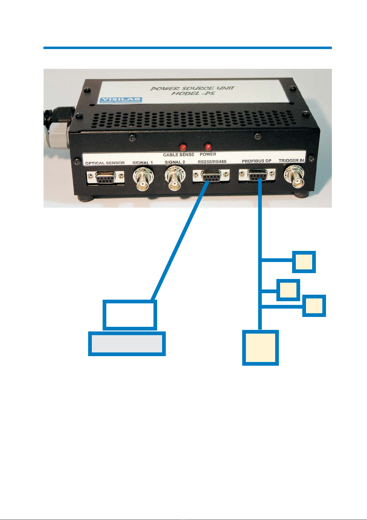
nication cable brings out the signals in analog and digital form and those signals are distributed with
the connectors at the front panel of the -PS. The serial port RS232 can be used for direct connection
to a PC or to a LAN232 unit which is used as a LAN for supporting the simultaneous use of up to eight
meters. The serial port can be configured as RS485 to be used as a wider LAN with long legs (up to
1200 meters). The LAN232 can again be used here as the bridge to the PC after configuring it to be
a member of the RS485 network. The regular D9 female connector has been used for this purpose
forsimplicity. Check each meter'smanuals to see thebaud rates it iscapable of using. Notethat using
the highest baud rate 115200 bauds is possible only with rather short cables. If long cables ( > 10
meters) is required, please use the lowest baud rate 9600 bauds for secured communications.
The Profibus DP is a standardized fieldbus for mill automation and is capable of very high speed
operation. It is usually built up with a twisted-pair cable connecting each of the DP slaves and the
DP masters. The D9 female is used here on the front panel for direct acceptance to the DP network.
The meter's GSD file or equivalent information needs to be fed to the master before it tries to identify
the slave.
The analog signals (a voltage) are led to the BNC connectors on the front panel, marked as Signal
1 and 2. The first one is for the signal selectable as moisture, web temperature, head temperature,
expansion module or extra temperature signals. The meter's own scaling may affect this and the
basic voltage range can be selected as 0-10 V, +/-5 V or 0-5 V as selected in the meter. The second
channel is only available if the meter has the proper option.
The third BNC connector is for direct connection to the triggering input (TTL levels, falling edge
sensitive). A microswitch or some transistor (e.g. an optotransistor) can be directly connected to it.
The last D9 female connector is for applying either the SICK optical sensor module WT18-2P112 or
equivalent or some tailored sensor system. Refer to Appendix 2 for details.
There are two indicator lights on the front panel. The one marked as POWER indicates the presence
of 24 V at the cable end. The second one (CABLE SENSE) indicates the connection of the cable to
the meter. However, this indicator is active only in model D meters and only if you have either the 12-
pin cable in use or you have both of the two 8-pin cables connected. The indicator is fed by the
isolated 5 V source from the meter and tells you that most likely the meter should be running OK.
A Note for AK40 and AK91 Users
Pleasebeaware that the meter AK40doesnot have the ProfibusDPbutdoes have the analogoutput
of 4-20 mA for the moisture signal. It is scaled as 100 % / 20 mA and 0 % at 4 mA unless otherwise noted.
The signal comes out of the D9 female connector marked for DP (X1) and the pin ordering is the
following.
X1 pin original purpose signal
3 PB B 4-20 mA out active
8 PB A 4-20 mA return (ground)
You can connect this output to your DCS as an active source. Note that the usual cable mounting
feedthrough is replaced with a 12-pin Cannon connector. The PS may be delivered with other
optional connectors depending on the particular application.