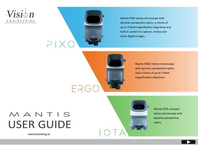
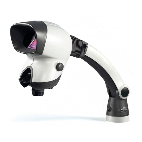
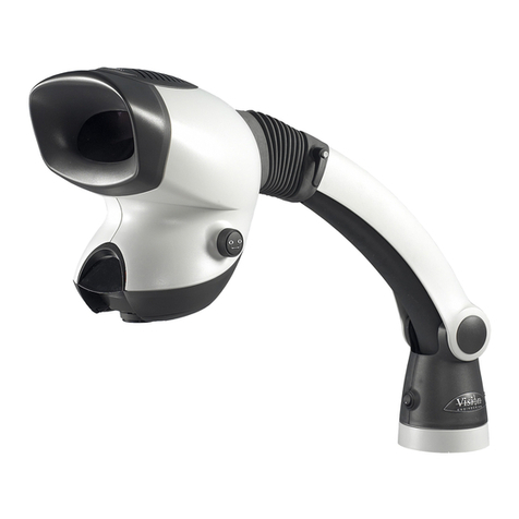
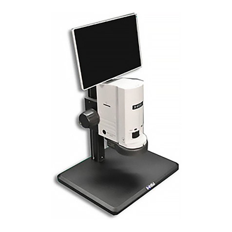
Vision Engineering Mantis Compact User manual

User Guide
Compact & Elite with Universal Stand

Table of Contents
English Mantis Compact 4 - 6
Mantis Elite 7 - 9
Français Mantis Compact 11 - 13
Mantis Elite 14 - 16
Deutsch Mantis Compact 18 - 20
Mantis Elite 21 - 23
Italiano Mantis Compact 25 - 27
Mantis Elite 28 - 30
Español Mantis Compact 32 - 34
Mantis Elite 35 - 37
日
日
本
本
語
語
Mantis Compact 39 - 41
Mantis Elite 42 - 44
中
中
文
文
Mantis Compact 46 - 48
Mantis Elite 49- 51
한
한
국
국
어
어
Mantis Compact 53 - 55
Mantis Elite 56 - 58
Р
Р
у
у
с
с
с
с
к
к
и
и
й
й
Mantis Compact 60 - 62
Mantis Elite 63 - 65

Health & Safety
Vision Engineering and its products conforms to the requirements of the EC Directives on Waste Electrical and Electronic
Equipment (WEEE) and Restriction of Hazardous Substances (RoHS).
Electrical Supply
Stand Input Voltage: 9VDC 1.7A
Power Supply Voltage (via plug top power supply) : 100-240VAC 50-60HZ 1.0A Max
Environmental Conditions
Indoor use
Altitude up to 2000m
Operating Temperature: 0°C - +40°C
Storage Temperature: 0°C to + 50°C for 3 months without any adverse effects
Maximum relative humidity 80% for temperatures up to 31°C decreasing linearly to 50% relative humidity at 40°C.
Mains voltage supply fluctuations not to exceed 10% of the nominal voltage
If equipment is not used in a manner as specified, protection provided by the equipment may be impaired.
The product should be located such that the Power Supply can be unplugged in the event of an emergency.

Mantis Compact with Universal Stand - User Guide www.visioneng.com/support
English
6
MANTIS COMPACT
Packing Contents
Assembly
Secure the universal mount to the work
surface using the G-clamp provided or by
using appropriate screws located in the
holes of the mount.
Place the universal arm on top of the
universal mount and lower it on to the
spigot until it is fully mounted.
Loosen the upper retaining bolt in the
universal arm. Remove the lower retaining
bolt . Carefully place the locating hook
of the Mantis viewing head over the
upper retaining bolt of the universal arm.
Replace the lower retaining bolt , ensuring
that the bolt passes through the lower locating mount
of the Mantis viewing head.
Tighten the upper and lower retaining bolts then re-seat the universal arm rubber
gaiter .
Remove the red transit plug from the underneath of the viewing head.
Fit and lock the chosen objective lens into the objective seat.
Ensuring the power adapter is suitable for your supply voltage, connect the power adapter
plug to a suitable power outlet and its output connector to the base of the universal arm.
Connect the output lead at the top of the universal arm to the rear of the viewing head.
Do not attempt to connect the power adapter directly to the viewing head.
Universal mount
G-clamp
Counter balanced boom stand
Viewing head
Power adapter
Objective lens
Desiccant Replacement
The desiccant removes excess moisture from the optical
head.
f Disconnect the power supply from the bottom of the
head.
f Remove the screw securing the desiccant cover and lift
the cover off.
f Insert the new desiccant and replace the desiccant cover.
LED Arrays
f Remove the desiccant cover .
f Remove the two crosshead screws that secure the LED
array and remove the array complete with filters .
f Reassembly is the reverse of this procedure.
Routine Maintenance
(sold seperately)
Mantis Compact with Universal Stand - User Guide www.visioneng.com/support
English
6
MANTIS COMPACT
Packing Contents
Assembly
Secure the universal mount to the work
surface using the G-clamp provided or by
using appropriate screws located in the
holes of the mount.
Place the universal arm on top of the
universal mount and lower it on to the
spigot until it is fully mounted.
Loosen the upper retaining bolt in the
universal arm. Remove the lower retaining
bolt . Carefully place the locating hook
of the Mantis viewing head over the
upper retaining bolt of the universal arm.
Replace the lower retaining bolt , ensuring
that the bolt passes through the lower locating mount
of the Mantis viewing head.
Tighten the upper and lower retaining bolts then re-seat the universal arm rubber
gaiter .
Remove the red transit plug from the underneath of the viewing head.
Fit and lock the chosen objective lens into the objective seat.
Ensuring the power adapter is suitable for your supply voltage, connect the power adapter
plug to a suitable power outlet and its output connector to the base of the universal arm.
Connect the output lead at the top of the universal arm to the rear of the viewing head.
Do not attempt to connect the power adapter directly to the viewing head.
Universal mount
G-clamp
Counter balanced boom stand
Viewing head
Power adapter
Objective lens
Desiccant Replacement
The desiccant removes excess moisture from the optical
head.
f Disconnect the power supply from the bottom of the
head.
f Remove the screw securing the desiccant cover and lift
the cover off.
f Insert the new desiccant and replace the desiccant cover.
LED Arrays
f Remove the desiccant cover .
f Remove the two crosshead screws that secure the LED
array and remove the array complete with filters .
f Reassembly is the reverse of this procedure.
Routine Maintenance
4

www.visioneng.com/support Mantis Compact with Universal Stand - User Guide
7
English
MANTIS COMPACT
Overview
Turn on the power switch Xand place the subject be-
neath the Mantis viewing head.
Focus
The aim of the universal stand products is that the height of
the instrument is set to a comfortable viewing position and the
subject is then lifted (normally by hand) into focus. Thus maintaining
optimum ergonomics.
To set the height of the instrument, ensure the friction clamp Yis
loosened then move the viewing head up or down until the required
viewing position is obtained and tighten the friction clamp.
Eye Spacing
Adjust the eye spacing control Zto obtain a comfortable stereo view.
Note: Adjusting the eye spacing is very important for viewing
comfort and must be adjusted for each Mantis user.
Changing Lenses
To change the objective lens, twist and remove lens [. Store the lens in the supplied container.
Fit and lock the chosen objective lens into the objective seat.
Head Counterbalance
When a lens has been changed, it may be necessary to adjust the head counterbalance. Adjust the
counterbalance screw \(clockwise for lighter lenses or counter-clockwise for heavier ones) until the viewing head does
not drift up or down when unsupported.
Ergonomic Viewing
An ergonomic posture will ensure that users fully benefit from the advantages provided by the Mantis optical technology.
In setting up your Mantis, firstly arrange your workspace, paying attention to the heights of the chair and table.
When seated with a straight back, your eyes should be comfortably lined up with the Mantis viewing head. Forearms
should be supported by the work surface.
Operation
General Care
f When not in use, cover your Mantis with the dust cover provided.
f Remove dust with a soft brush or cleaning cloth.
f The Mantis lenses should be cleaned with a lens cleaning cloth.
f Keep accessories in a dust-free environment when not in use.
Service
Service and repair work must only be carried out by service engineers authorised by Vision Engineering.
This product is warranted to be free from defects in material and workmanship for a period of one year from the date of invoice to the original purchaser.
If during the warranty period the product is found to be defective, it will be repaired or replaced at facilities of Vision Engineering or elsewhere, all at the
option of Vision Engineering. However, Vision Engineering reserves the right to refund the purchase price if it is unable to provide replacement, and repair is
not commercially practicable or cannot be timely made. Parts not of Vision Engineering manufacture carry only the warranty of their manufacturer. Expendable
components such as fuses carry no warranty.
This warranty does not cover damage in transit, damage caused by misuse, neglect, or carelessness, or damage resulting from either improper servicing or
modification by other than Vision Engineering approved service personnel. Further, this warranty does not cover any routine maintenance work on the product
described in the user guide or any minor maintenance work which is reasonably expected to be performed by the purchaser.
No responsibility is assumed for unsatisfactory operating performance due to environmental conditions such as humidity, dust, corrosive chemicals, deposition
of oil or other foreign matter, spillage, or other conditions beyond the control of Vision Engineering.
Except as stated herein, Vision Engineering makes no other warranties, express or implied by law, whether for resale, fitness for a particular purpose or
otherwise. Further, Vision Engineering shall not under any circumstances be liable for incidental, consequential or other damages.
Warranty
Mantis Compact with Universal Stand - User Guide www.visioneng.com/support
English
6
MANTIS COMPACT
Packing Contents
Assembly
Secure the universal mount to the work
surface using the G-clamp provided or by
using appropriate screws located in the
holes of the mount.
Place the universal arm on top of the
universal mount and lower it on to the
spigot until it is fully mounted.
Loosen the upper retaining bolt in the
universal arm. Remove the lower retaining
bolt . Carefully place the locating hook
of the Mantis viewing head over the
upper retaining bolt of the universal arm.
Replace the lower retaining bolt , ensuring
that the bolt passes through the lower locating mount
of the Mantis viewing head.
Tighten the upper and lower retaining bolts then re-seat the universal arm rubber
gaiter .
Remove the red transit plug from the underneath of the viewing head.
Fit and lock the chosen objective lens into the objective seat.
Ensuring the power adapter is suitable for your supply voltage, connect the power adapter
plug to a suitable power outlet and its output connector to the base of the universal arm.
Connect the output lead at the top of the universal arm to the rear of the viewing head.
Do not attempt to connect the power adapter directly to the viewing head.
Universal mount
G-clamp
Counter balanced boom stand
Viewing head
Power adapter
Objective lens
Desiccant Replacement
The desiccant removes excess moisture from the optical
head.
f Disconnect the power supply from the bottom of the
head.
f Remove the screw securing the desiccant cover and lift
the cover off.
f Insert the new desiccant and replace the desiccant cover.
LED Arrays
f Remove the desiccant cover .
f Remove the two crosshead screws that secure the LED
array and remove the array complete with filters .
f Reassembly is the reverse of this procedure.
Routine Maintenance
5

Mantis Compact with Universal Stand - User Guide www.visioneng.com/support
English
8
MANTIS COMPACT
English
Mantis Compact Product Family
Lighting Data
LUX intensity measured at subject plane with colour correction filters.
20 LEDs 9,400 LUX 10,000 hours
Power Supply
9V DC external plug transformer
Accessories
Lens protection caps
Floating Stage (for bench stand)
Dust Cover
Replacement LED Array
Specification
Objective Lenses Working Distance Field of View
x4 96mm 27.5mm
x6 73mm 19.2mm
Objective Lenses
x2 167mm 45.0mm
Mantis Compact with Universal Sta
nd - User Guide www.visioneng.com/support
English
8
MANTIS COMPACT
English
Mantis Compact Product Family
Lighting Data
LUX intensity measured at subject plane with colour correction filters.
20 LEDs 9,400 LUX 10,000 hours
Power Supply
9V DC external plug transformer
Accessories
Lens protection caps
Floating Stage (for bench stand)
Dust Cover
Replacement LED Array
Specification
Objective Lenses Working Distance Field of View
x4 96mm 27.5mm
x6 73mm 19.2mm
Objective Lenses
x2 167mm 45.0mm
Mantis Compact with Universal Stand - User Guide www.visioneng.com/support
English
8
MANTIS COMPACT
English
Mantis Compact Product Family
Lighting Data
LUX intensity measured at subject plane with colour correction filters.
20 LEDs 9,400 LUX 10,000 hours
Power Supply
9V DC external plug transformer
Accessories
Lens protection caps
Floating Stage (for bench stand)
Dust Cover
Replacement LED Array
Specification
Objective Lenses Working Distance Field of View
x4 96mm 27.5mm
x6 73mm 19.2mm
Objective Lenses
x2 167mm 45.0mm
x8 58.5mm 14.3mm
6

MANTIS ELITE
www.visioneng.com/support Mantis Elite with Universal Stand - User Guide
English
9
Desiccant Replacement
The desiccant removes excess moisture from the optical head.
f Disconnect the power supply from the bottom of the head.
f Remove the grommet covering the desiccant and remove the
desiccant.
f Insert the new desiccant and replace the grommet.
LED Arrays
The method for removing the LED arrays is identical for either side.
f Disconnect the power supply from the bottom of the head.
f Loosen the two screws that secure the filter/array cover and
remove the cover.
f Lift out the LED array and turn it over. Disconnect the array connector and
remove the LED array complete with filter .
f Reassembly is the reverse of this procedure.
Packing Contents
Assembly
Secure the universal mount to the work surface using
the G-clamp provided or by using appropriate
screws located in the counter bored holes of the
Mount.
Place the universal arm on top of the universal
mount. Lower onto spigot until fully mounted.
Loosen the upper retaining bolt on the universal arm. Remove
the lower retaining bolt . Carefully place the Mantis viewing
head’s locating hook over the upper retaining bolt of the universal
arm.
Replace the lower retaining bolt, ensuring the
bolt passes through the lower locating mount
of the Mantis viewing head.
Tighten the upper and lower retaining bolts then
re-seat the universal arm rubber gaiter .
Fit the chosen objective lens into the
objective seat (ensuring the Vision logo is at the
front) and tighten the securing screw . If
required, rotate the objective turret and fit
another objective lens in the same way.
Ensuring the power adapter is suitable for your supply voltage, connect the power adapter plug to a suitable power
outlet and its output connector to the base of the universal arm.
Connect the output lead at the top of the universal arm to the rear of the viewing head.
Do not attempt to connect the power supply directly to the viewing head.
Universal mount
G-clamp
Counter balanced boom stand
Viewing head
Power adapter
Objective lens
Anti glare hood
Routine Maintenance
(sold seperately)
MANTIS ELITE
Mantis Elite with Universal Stand - User Guide www.visioneng.com/support
English
10
Overview
Turn on the power switch Xand place the subject
beneath the Mantis viewing head.
Focus
Ensuring the friction clamp Yis loosened, move the viewing
head up or down until the subject is in focus.
When focused, tighten the friction clamp.
Eye Spacing
Adjust the eye spacing control Zto obtain a
comfortable stereo view.
Note: Adjusting the eye spacing is very important for viewing
comfort and must be adjusted for each Mantis user.
Changing Lenses
To change an objective lens [, loosen the lens securing screw \and remove
the lens. Store the lens in the supplied holder.
Fit the chosen objective lens into the objective seat and tighten the securing
screw.
Alternatively, rotate the objective turret ]to bring the second objective into use.
Head Counterbalance
When a lens has been changed, it may be necessary to adjust the head counterbalance. Adjust the counterbalance screw
^(clockwise for lighter lenses or counter-clockwise for heavier ones) until the viewing head does not drift up or down
when unsupported.
Tilt Adjustment of Head (optional)
Loosen the tilt adjustment friction control _, move the viewing head up or down to the required position and tighten the
friction control.
Hood Removal
In certain lighting environments it may improve viewing by removing the anti glare hood `.
Operation
General Care
f Cover your Mantis with a dust cover when not in use.
f Remove dust with a soft brush or cleaning cloth.
f The Mantis viewing screen and lenses should be cleaned with a lens cleaning cloth.
f Keep accessories in a dust-free environment when not in use.
Service
Service and repair work must only be carried out by service engineers authorised by Vision Engineering.
This product is warranted to be free from defects in material and workmanship for a period of one year from the date of invoice to the original purchaser.
If during the warranty period the product is found to be defective, it will be repaired or replaced at facilities of Vision Engineering or elsewhere, all at the op-
tion of Vision Engineering. However, Vision Engineering reserves the right to refund the purchase price if it is unable to provide replacement, and repair is not
commercially practicable or cannot be timely made. Parts not of Vision Engineering manufacture carry only the warranty of their manufacturer. Expendable
components such as fuses carry no warranty.
This warranty does not cover damage in transit, damage caused by misuse, neglect, or carelessness, or damage resulting from either improper servicing or
modification by other than Vision Engineering approved service personnel. Further, this warranty does not cover any routine maintenance work on the product
described in the user guide or any minor maintenance work which is reasonably expected to be performed by the purchaser.
No responsibility is assumed for unsatisfactory operating performance due to environmental conditions such as humidity, dust, corrosive chemicals, deposition
of oil or other foreign matter, spillage, or other conditions beyond the control of Vision Engineering.
Except as stated herein, Vision Engineering makes no other warranties, express or implied by law, whether for resale, fitness for a particular purpose or other-
wise. Further, Vision Engineering shall not under any circumstances be liable for incidental, consequential or other damages.
Warranty
7

MANTIS ELITE
Mantis Elite with Universal Stand - User Guide www.visioneng.com/support
English
10
Overview
Turn on the power switch Xand place the subject
beneath the Mantis viewing head.
Focus
Ensuring the friction clamp Yis loosened, move the viewing
head up or down until the subject is in focus.
When focused, tighten the friction clamp.
Eye Spacing
Adjust the eye spacing control Zto obtain a
comfortable stereo view.
Note: Adjusting the eye spacing is very important for viewing
comfort and must be adjusted for each Mantis user.
Changing Lenses
To change an objective lens [, loosen the lens securing screw \and remove
the lens. Store the lens in the supplied holder.
Fit the chosen objective lens into the objective seat and tighten the securing
screw.
Alternatively, rotate the objective turret ]to bring the second objective into use.
Head Counterbalance
When a lens has been changed, it may be necessary to adjust the head counterbalance. Adjust the counterbalance screw
^(clockwise for lighter lenses or counter-clockwise for heavier ones) until the viewing head does not drift up or down
when unsupported.
Tilt Adjustment of Head (optional)
Loosen the tilt adjustment friction control _, move the viewing head up or down to the required position and tighten the
friction control.
Hood Removal
In certain lighting environments it may improve viewing by removing the anti glare hood `.
Operation
General Care
f Cover your Mantis with a dust cover when not in use.
f Remove dust with a soft brush or cleaning cloth.
f The Mantis viewing screen and lenses should be cleaned with a lens cleaning cloth.
f Keep accessories in a dust-free environment when not in use.
Service
Service and repair work must only be carried out by service engineers authorised by Vision Engineering.
This product is warranted to be free from defects in material and workmanship for a period of one year from the date of invoice to the original purchaser.
If during the warranty period the product is found to be defective, it will be repaired or replaced at facilities of Vision Engineering or elsewhere, all at the op-
tion of Vision Engineering. However, Vision Engineering reserves the right to refund the purchase price if it is unable to provide replacement, and repair is not
commercially practicable or cannot be timely made. Parts not of Vision Engineering manufacture carry only the warranty of their manufacturer. Expendable
components such as fuses carry no warranty.
This warranty does not cover damage in transit, damage caused by misuse, neglect, or carelessness, or damage resulting from either improper servicing or
modification by other than Vision Engineering approved service personnel. Further, this warranty does not cover any routine maintenance work on the product
described in the user guide or any minor maintenance work which is reasonably expected to be performed by the purchaser.
No responsibility is assumed for unsatisfactory operating performance due to environmental conditions such as humidity, dust, corrosive chemicals, deposition
of oil or other foreign matter, spillage, or other conditions beyond the control of Vision Engineering.
Except as stated herein, Vision Engineering makes no other warranties, express or implied by law, whether for resale, fitness for a particular purpose or other-
wise. Further, Vision Engineering shall not under any circumstances be liable for incidental, consequential or other damages.
Warranty
8

MANTIS ELITE
www.visioneng.com/support Mantis Elite with Universal Stand - User Guide
English
11
Mantis Elite Product Family
Specification
Power Supply
9V DC external plug transformer
Accessories
Lens protection caps
Floating Stage (for each bench stand)
Dust Cover
Replacement LED Array
Lighting Data
LUX intensity measured at subject plane with colour correction filters.
24 LEDs 11,000 LUX 10,000 hours
Objective Lenses Working Distance Field of View
x4 96mm 34.0mm
x6 68mm 23.0mm
Objective Lenses
x8 59mm 17.0mm
x10 54mm 13.5mm
x15 40mm 8.8mm
x20 29mm 6.5mm
X6 SLWD* 112mm 20.0mm
x2 160mm 57.0mm
*Single mount objective replaces twin
turret assembly.
*Single mount objecve replaces
twin turret assembly. Can’t be used
with 2x or 20x objecves.
MANTIS ELITE
Mantis Elite with Universal Stand - User Guide www.visioneng.com/support
English
10
Overview
Turn on the power switch Xand place the subject
beneath the Mantis viewing head.
Focus
Ensuring the friction clamp Yis loosened, move the viewing
head up or down until the subject is in focus.
When focused, tighten the friction clamp.
Eye Spacing
Adjust the eye spacing control Zto obtain a
comfortable stereo view.
Note: Adjusting the eye spacing is very important for viewing
comfort and must be adjusted for each Mantis user.
Changing Lenses
To change an objective lens [, loosen the lens securing screw \and remove
the lens. Store the lens in the supplied holder.
Fit the chosen objective lens into the objective seat and tighten the securing
screw.
Alternatively, rotate the objective turret ]to bring the second objective into use.
Head Counterbalance
When a lens has been changed, it may be necessary to adjust the head counterbalance. Adjust the counterbalance screw
^(clockwise for lighter lenses or counter-clockwise for heavier ones) until the viewing head does not drift up or down
when unsupported.
Tilt Adjustment of Head (optional)
Loosen the tilt adjustment friction control _, move the viewing head up or down to the required position and tighten the
friction control.
Hood Removal
In certain lighting environments it may improve viewing by removing the anti glare hood `.
Operation
General Care
f Cover your Mantis with a dust cover when not in use.
f Remove dust with a soft brush or cleaning cloth.
f The Mantis viewing screen and lenses should be cleaned with a lens cleaning cloth.
f Keep accessories in a dust-free environment when not in use.
Service
Service and repair work must only be carried out by service engineers authorised by Vision Engineering.
This product is warranted to be free from defects in material and workmanship for a period of one year from the date of invoice to the original purchaser.
If during the warranty period the product is found to be defective, it will be repaired or replaced at facilities of Vision Engineering or elsewhere, all at the op-
tion of Vision Engineering. However, Vision Engineering reserves the right to refund the purchase price if it is unable to provide replacement, and repair is not
commercially practicable or cannot be timely made. Parts not of Vision Engineering manufacture carry only the warranty of their manufacturer. Expendable
components such as fuses carry no warranty.
This warranty does not cover damage in transit, damage caused by misuse, neglect, or carelessness, or damage resulting from either improper servicing or
modification by other than Vision Engineering approved service personnel. Further, this warranty does not cover any routine maintenance work on the product
described in the user guide or any minor maintenance work which is reasonably expected to be performed by the purchaser.
No responsibility is assumed for unsatisfactory operating performance due to environmental conditions such as humidity, dust, corrosive chemicals, deposition
of oil or other foreign matter, spillage, or other conditions beyond the control of Vision Engineering.
Except as stated herein, Vision Engineering makes no other warranties, express or implied by law, whether for resale, fitness for a particular purpose or other-
wise. Further, Vision Engineering shall not under any circumstances be liable for incidental, consequential or other damages.
Warranty
9

Santé et sécurité
Vision Engineering et ses produits sont conformes aux exigences des directives européennes sur les Déchets d'équipements
électriques et électroniques (Directive DEEE) et sur la Limitation de l'utilisation de certaines substances dangereuses
(Directive RoHS).

14 Mantis Compact avec statif universel – Guide d’utilisation www.visioneng.com/support
Français
MANTIS COMPACT
Français
Contenu des colis
Montage
Fixer l’embase sur le plan de travail avec le serre-joint fourni ou en la vissant au travers des trous réservés à cet usage.
Placer le bras articulé sur l’embase en l’enfonçant au maximum sur l’axe.
Désserrer le boulon supérieur sur le
bras articulé. Enlever le boulon du bas
. Placer délicatement le crochet de
fixation de la tête Mantis sur le
boulon supérieur du bras articulé.
Replacer le boulon du bas , en s’assurant
qu’il passe dans le trou prévu à cet effet dans la tête
Mantis.
Serrer le boulon du haut et mettre en
place le manchon en caoutchouc .
Retirer la pièce rouge destinée au transport
sous la tête.
Insérer et verrouiller l’objectif choisi sous la tête.
S’assurer que l’alimentation correspond à la tension secteur, la
brancher à la prise murale et dans le connecteur situé sur la base du bras articulé.
Connecter le cable situé en haut du bras à l’arrière de la tête.
Ne jamais tenter de connecter l’alimentation secteur directement sur la
tête.
Embase
Serre joint
Bras articulé
Tête de projection
Alimentation secteur
Objectif
Remplacement du dessiccant
Le dessiccant enlève l’excès d’humidité de la tête.
f Déconnecter l’alimentation de la tête.
f Retirer la vis du cache dessiccant et ôter le
couvercle.
f Remplacer le dessiccant.
LED Arrays
f Retirer le cache du dessiccant .
f Retirer les 2 vis cruciformes qui tiennent le support
des LED et retirer l’ensemble avec les filtres .
Remonter dans l’ordre inverse.
Maintenance de routine
14
Mantis Compact avec statif universel – Guide d’utilisation www.visioneng.com/support
Français
MANTIS COMPACT
Français
Contenu des colis
Montage
Fixer l’embase sur le plan de travail avec le serre-joint fourni ou en la vissant au travers des trous réservés à cet usage.
Placer le bras articulé sur l’embase en l’enfonçant au maximum sur l’axe.
Désserrer le boulon supérieur sur le
bras articulé. Enlever le boulon du bas
. Placer délicatement le crochet de
fixation de la tête Mantis sur le
boulon supérieur du bras articulé.
Replacer le boulon du bas , en s’assurant
qu’il passe dans le trou prévu à cet effet dans la tête
Mantis.
Serrer le boulon du haut et mettre en
place le manchon en caoutchouc .
Retirer la pièce rouge destinée au transport
sous la tête.
Insérer et verrouiller l’objectif choisi sous la tête.
S’assurer que l’alimentation correspond à la tension secteur, la
brancher à la prise murale et dans le connecteur situé sur la base du bras articulé.
Connecter le cable situé en haut du bras à l’arrière de la tête.
Ne jamais tenter de connecter l’alimentation secteur directement sur la
tête.
Embase
Serre joint
Bras articulé
Tête de projection
Alimentation secteur
Objectif
Remplacement du dessiccant
Le dessiccant enlève l’excès d’humidité de la tête.
f Déconnecter l’alimentation de la tête.
f Retirer la vis du cache dessiccant et ôter le
couvercle.
f Remplacer le dessiccant.
LED Arrays
f Retirer le cache du dessiccant .
f Retirer les 2 vis cruciformes qui tiennent le support
des LED et retirer l’ensemble avec les filtres .
Remonter dans l’ordre inverse.
Maintenance de routine
10

15
www.visioneng.com/support Mantis Compact avec statif universel – Guide d’utilisation
Français
MANTIS COMPACT
Général
Presser l’interrupteur de puissance Xet placer un sujet
sous la tête.
Mise au point
Le but du statif universel (bras articulé) est d’être réglé
confortablement à la bonne hauteur des yeux et ensuite de
prendre le sujet à la main et de le focaliser, offrant ainsi une ergono-
mie optimale.
Pour régler la hauteur de l’instrument, s’assurer que la vis de friction
Y est désserrée, puis ajuster la tête en bas ou en haut jusqu’à la
bonne hauteur, puis resserrer la vis.
Ecartement des yeux
Ajuster le bouton d’écartement des yeux Zpour obtenir une vision sté-
réoscopique confortable.
Note: Ajuster l’écartement des yeux est très important pour le
confort de vision et doit être fait pour chaque utilisateur.
Changement d’objectif
Pour changer d’objectif, le tourner et le retirer [. Le replacer dans sa boite.
Enfoncer et tourner le nouvel objectif dans son réceptacle.
Contrepoids de la tête
Quand on change un objectif il peut être nécessaire de régler le contrepoids. Ajuster la vis \(dans le sens horaire pour un
objectif léger et vice versa) jusqu’à ce que la tête reste immobile lorsqu’elle n’est pas tenue.
Vision ergonomique
Une posture ergonomique est nécessaire pour tirer avantage de la technologie optique de la Mantis.
En réglant votre Mantis porter attention à l’espace de travail, en particulier à la hauteur de la chaise et de la table.
En étant assis avec le dos droit, les yeux doivent être à hauteur de la tête Mantis et les avant bras reposer sur la table.
Utilisation
Ce produit est garanti exempt de défauts dans le matériel et la fabrication pendant une période d'un an de la date de la facture à l'acheteur final.
Si pendant la période de garantie le produit s'avère défectueux, il sera réparé ou remplacé chez Vision Engineering ou ailleurs, au choix de Vision Engineering.
Cependant, Vision Engineering se réserve le droit de rembourser le prix d'achat s'il ne peut pas fournir le remplacement, si ce n'est pas commercialement
faisable ou si le produit ne peut être dépanné. Les parties qui ne sont pas fabriquées par Vision Engineering sont garantis par leur fabricant. Les composants
consommables tels que des fusibles ne portent aucune garantie.
Cette garantie ne couvre pas des dommages en transit, des dommages provoqués par l'abus, la négligence, ou l'inattention, ou des dommages résultant de
l'entretien inexact ou de la modification par d’autre que le personnel de service approuvé par Vision Engineering. De plus, cette garantie ne couvre aucun
travail d'entretien courant sur le produit décrit dans le guide d'utilisateur ou aucun travail mineur d'entretien qui est raisonnablement attendu être effectué par
l'acheteur.
Aucune responsabilité n'est assumée d’un fonctionnement insuffisant du aux conditions environnementales telles que l'humidité, la poussière, les produits
chimiques corrosifs, le dépôt d'huile ou d'autres corps étrangers, le débordement, ou d'autres conditions indépendantes de la volonté de Vision Engineering.
Excepté comme indiqué ci-dessus, Vision Engineering n’appliquera aucune autre garantie de quel ordre que ce soit. De plus, Vision Engineering ne sera, en
aucune circonstance, rendu responsable de dommages fortuits, consécutifs ou autres.
Garantie
Conseils
f Quand la Mantis n’est pas utilisée elle doit être recouverte d’une housse.
f Enlever la poussière avec un brosse douce ou un chiffon propre.
f Les objectifs doivent être nettoyés avec un nettoyant pour verres de lunettes.
f Garder les accessoires à l’abri de la lumière.
Dépannage
Le dépannage et les réparations doivent être effectués par du personnel agréé Vision Engineering.
14
Mantis Compact avec statif universel – Guide d’utilisation www.visioneng.com/support
Français
MANTIS COMPACT
Français
Contenu des colis
Montage
Fixer l’embase sur le plan de travail avec le serre-joint fourni ou en la vissant au travers des trous réservés à cet usage.
Placer le bras articulé sur l’embase en l’enfonçant au maximum sur l’axe.
Désserrer le boulon supérieur sur le
bras articulé. Enlever le boulon du bas
. Placer délicatement le crochet de
fixation de la tête Mantis sur le
boulon supérieur du bras articulé.
Replacer le boulon du bas , en s’assurant
qu’il passe dans le trou prévu à cet effet dans la tête
Mantis.
Serrer le boulon du haut et mettre en
place le manchon en caoutchouc .
Retirer la pièce rouge destinée au transport
sous la tête.
Insérer et verrouiller l’objectif choisi sous la tête.
S’assurer que l’alimentation correspond à la tension secteur, la
brancher à la prise murale et dans le connecteur situé sur la base du bras articulé.
Connecter le cable situé en haut du bras à l’arrière de la tête.
Ne jamais tenter de connecter l’alimentation secteur directement sur la
tête.
Embase
Serre joint
Bras articulé
Tête de projection
Alimentation secteur
Objectif
Remplacement du dessiccant
Le dessiccant enlève l’excès d’humidité de la tête.
f Déconnecter l’alimentation de la tête.
f Retirer la vis du cache dessiccant et ôter le
couvercle.
f Remplacer le dessiccant.
LED Arrays
f Retirer le cache du dessiccant .
f Retirer les 2 vis cruciformes qui tiennent le support
des LED et retirer l’ensemble avec les filtres .
Remonter dans l’ordre inverse.
Maintenance de routine
12

x8 58.5mm 14.3mm
14
Mantis Compact avec statif universel – Guide d’utilisation www.visioneng.com/support
Français
MANTIS COMPACT
Français
Contenu des colis
Montage
Fixer l’embase sur le plan de travail avec le serre-joint fourni ou en la vissant au travers des trous réservés à cet usage.
Placer le bras articulé sur l’embase en l’enfonçant au maximum sur l’axe.
Désserrer le boulon supérieur sur le
bras articulé. Enlever le boulon du bas
. Placer délicatement le crochet de
fixation de la tête Mantis sur le
boulon supérieur du bras articulé.
Replacer le boulon du bas , en s’assurant
qu’il passe dans le trou prévu à cet effet dans la tête
Mantis.
Serrer le boulon du haut et mettre en
place le manchon en caoutchouc .
Retirer la pièce rouge destinée au transport
sous la tête.
Insérer et verrouiller l’objectif choisi sous la tête.
S’assurer que l’alimentation correspond à la tension secteur, la
brancher à la prise murale et dans le connecteur situé sur la base du bras articulé.
Connecter le cable situé en haut du bras à l’arrière de la tête.
Ne jamais tenter de connecter l’alimentation secteur directement sur la
tête.
Embase
Serre joint
Bras articulé
Tête de projection
Alimentation secteur
Objectif
Remplacement du dessiccant
Le dessiccant enlève l’excès d’humidité de la tête.
f Déconnecter l’alimentation de la tête.
f Retirer la vis du cache dessiccant et ôter le
couvercle.
f Remplacer le dessiccant.
LED Arrays
f Retirer le cache du dessiccant .
f Retirer les 2 vis cruciformes qui tiennent le support
des LED et retirer l’ensemble avec les filtres .
Remonter dans l’ordre inverse.
Maintenance de routine
13

MANTIS ELITE
www.visioneng.com/support Mantis Elite avec statif universel – Guide d’utilisation
17
Français
Remplacement du dessiccant
Le dessiccant enlève l’excès d’humidité de la tête.
f Déconnecter l’alimentation de la tête.
f Retirer le bouchon et ôter la cartouche.
f Remplacer le dessiccant, replacer le bouchon.
Ensemble LED
La méthode est la même pour les deux cotés.
f Déconnecter l’alimentation de la tête.
f Retirer les 2 vis cruciformes qui tiennent le support de filtre et
les LED et retirer le couvercle .
f Soulever la rangée de LED et la retourner. Retirer le connecteur ,
puis l’ensemble avec le filtre .
f Remonter dans l’ordre inverse.
Contenu des colis
Montage
Fixer l’embase sur le plan de travail avec le serre-joint
fourni ou en la vissant au travers des trous réservés
à cet usage.
Placer le bras articulé sur l’embase en
l’enfonçant au maximum sur l’axe.
Desserrer le boulon supérieur sur le bras articulé.
Enlever le boulon du bas . Placer délicatement le crochet
de fixation de la tête Mantis sur le boulon supérieur du bras
articulé.
Replacer le boulon du bas, en s’assurant qu’il
passe dans le trou prévu à cet effet dans la tête
Mantis.
Serrer le boulon du haut et mettre en place le
manchon en caoutchouc .
Insérer l’objectif choisi dans
l’emplacement prévu(avec le logo Vision sur
l’avant) et serrer la vis de fixation . Si
nécessaire, tourner la tourelle et monter un
autre objectif de la même manière.
S’assurer que l’alimentation correspond à la tension secteur, la brancher à la prise murale et dans le connecteur situé
sur la base du bras articulé.
Connecter le cable situé en haut du bras à l’arrière de la tête.
Ne jamais tenter de connecter l’alimentation secteur directement sur la tête.
Embase
Serre joint
Bras articulé
Tête de projection
Alimentation secteur
Objectif
Visière anti reflets
Maintenance de routine
Objecf vendu séparément
14
MANTIS ELITE
Mantis Elte avec statif universel – Guide d’utilisation www.visioneng.com/support
18
Français
Général
Presser l’interrupteur de puissance Xet placer un sujet
sous la tête.
Mise au point
Le but du statif universel (bras articulé) est d’être réglé
confortablement à la bonne hauteur des yeux et ensuite de
prendre le sujet à la main et de le focaliser, offrant ainsi
une ergonomie optimale.
Pour régler la hauteur de l’instrument, s’assurer que la
vis de friction Yest désserrée, puis ajuster la tête en bas
ou en haut jusqu’à la bonne hauteur, puis resserrer la vis.
Ecartement des yeux
Ajuster le bouton d’écartement des yeux Zpour obtenir une vision
stéréoscopique confortable.
Note: Ajuster l’écartement des yeux est très important pour le confort de vision
et doit être fait pour chaque utilisateur.
Changement d’objectif
Pour changer un objectif [, desserrer la vis \et retirer l’objectif. Le remettre dans sa boite.
Mettre en place le nouvel objectif et resserrer la vis.
Sinon, tourner la tourelle ]pour utiliser le deuxième objectif.
Contre-poids de la tête
Quand on change un objectif il peut être nécessaire de régler le contrepoids. Ajuster la vis ^(dans le sens horaire pour un
objectif léger et vice versa) jusqu’à ce que la tête reste immobile lorsqu’elle n’est pas tenue.
Ajustement angulaire de la tête (en option)
Desserrer la vis de friction _, déplacer la tête vers le haut ou vers le bas jusqu’à la position choisie. Resserrer la vis.
Visière anti reflêts
Dans certains environnements lumineux il peut être préférable d’enlever la visière `.
Utilisation
Conseils
f Quand la Mantis n’est pas utilisée elle doit être recouverte d’une housse.
f Enlever la poussière avec un brosse douce ou un chiffon propre.
f Les objectifs doivent être nettoyés avec un nettoyant pour verres de lunettes.
f Garder les accessoires à l’abri de la lumière.
Dépannage
Le dépannage et les réparations doivent être effectués par du personnel agréé Vision Engineering.
Ce produit est garanti exempt de défauts dans le matériel et la fabrication pendant une période d'un an de la date de la facture à l'acheteur final.
Si pendant la période de garantie le produit s'avère défectueux, il sera réparé ou remplacé chez Vision Engineering ou ailleurs, au choix de Vision Engineering.
Cependant, Vision Engineering se réserve le droit de rembourser le prix d'achat s'il ne peut pas fournir le remplacement, si ce n'est pas commercialement
faisable ou si le produit ne peut être dépanné. Les parties qui ne sont pas fabriquées par Vision Engineering sont garantis par leur fabricant. Les composants
consommables tels que des fusibles ne portent aucune garantie.
Cette garantie ne couvre pas des dommages en transit, des dommages provoqués par l'abus, la négligence, ou l'inattention, ou des dommages résultant de
l'entretien inexact ou de la modification par d’autre que le personnel de service approuvé par Vision Engineering. De plus, cette garantie ne couvre aucun
travail d'entretien courant sur le produit décrit dans le guide d'utilisateur ou aucun travail mineur d'entretien qui est raisonnablement attendu être effectué par
l'acheteur.
Aucune responsabilité n'est assumée d’un fonctionnement insuffisant du aux conditions environnementales telles que l'humidité, la poussière, les produits
chimiques corrosifs, le dépôt d'huile ou d'autres corps étrangers, le débordement, ou d'autres conditions indépendantes de la volonté de Vision Engineering.
Excepté comme indiqué ci-dessus, Vision Engineering n’appliquera aucune autre garantie de quel ordre que ce soit. De plus, Vision Engineering ne sera, en
aucune circonstance, rendu responsable de dommages fortuits, consécutifs ou autres.
Garantie
15
MANTIS ELITE
Mantis Elte avec statif universel – Guide d’utilisation www.visioneng.com/support
18
Français
Général
Presser l’interrupteur de puissance Xet placer un sujet
sous la tête.
Mise au point
Le but du statif universel (bras articulé) est d’être réglé
confortablement à la bonne hauteur des yeux et ensuite de
prendre le sujet à la main et de le focaliser, offrant ainsi
une ergonomie optimale.
Pour régler la hauteur de l’instrument, s’assurer que la
vis de friction Yest désserrée, puis ajuster la tête en bas
ou en haut jusqu’à la bonne hauteur, puis resserrer la vis.
Ecartement des yeux
Ajuster le bouton d’écartement des yeux Zpour obtenir une vision
stéréoscopique confortable.
Note: Ajuster l’écartement des yeux est très important pour le confort de vision
et doit être fait pour chaque utilisateur.
Changement d’objectif
Pour changer un objectif [, desserrer la vis \et retirer l’objectif. Le remettre dans sa boite.
Mettre en place le nouvel objectif et resserrer la vis.
Sinon, tourner la tourelle ]pour utiliser le deuxième objectif.
Contre-poids de la tête
Quand on change un objectif il peut être nécessaire de régler le contrepoids. Ajuster la vis ^(dans le sens horaire pour un
objectif léger et vice versa) jusqu’à ce que la tête reste immobile lorsqu’elle n’est pas tenue.
Ajustement angulaire de la tête (en option)
Desserrer la vis de friction _, déplacer la tête vers le haut ou vers le bas jusqu’à la position choisie. Resserrer la vis.
Visière anti reflêts
Dans certains environnements lumineux il peut être préférable d’enlever la visière `.
Utilisation
Conseils
f Quand la Mantis n’est pas utilisée elle doit être recouverte d’une housse.
f Enlever la poussière avec un brosse douce ou un chiffon propre.
f Les objectifs doivent être nettoyés avec un nettoyant pour verres de lunettes.
f Garder les accessoires à l’abri de la lumière.
Dépannage
Le dépannage et les réparations doivent être effectués par du personnel agréé Vision Engineering.
Ce produit est garanti exempt de défauts dans le matériel et la fabrication pendant une période d'un an de la date de la facture à l'acheteur final.
Si pendant la période de garantie le produit s'avère défectueux, il sera réparé ou remplacé chez Vision Engineering ou ailleurs, au choix de Vision Engineering.
Cependant, Vision Engineering se réserve le droit de rembourser le prix d'achat s'il ne peut pas fournir le remplacement, si ce n'est pas commercialement
faisable ou si le produit ne peut être dépanné. Les parties qui ne sont pas fabriquées par Vision Engineering sont garantis par leur fabricant. Les composants
consommables tels que des fusibles ne portent aucune garantie.
Cette garantie ne couvre pas des dommages en transit, des dommages provoqués par l'abus, la négligence, ou l'inattention, ou des dommages résultant de
l'entretien inexact ou de la modification par d’autre que le personnel de service approuvé par Vision Engineering. De plus, cette garantie ne couvre aucun
travail d'entretien courant sur le produit décrit dans le guide d'utilisateur ou aucun travail mineur d'entretien qui est raisonnablement attendu être effectué par
l'acheteur.
Aucune responsabilité n'est assumée d’un fonctionnement insuffisant du aux conditions environnementales telles que l'humidité, la poussière, les produits
chimiques corrosifs, le dépôt d'huile ou d'autres corps étrangers, le débordement, ou d'autres conditions indépendantes de la volonté de Vision Engineering.
Excepté comme indiqué ci-dessus, Vision Engineering n’appliquera aucune autre garantie de quel ordre que ce soit. De plus, Vision Engineering ne sera, en
aucune circonstance, rendu responsable de dommages fortuits, consécutifs ou autres.
Garantie

MANTIS ELITE
www.visioneng.com/support Mantis Elite avec statif universel – Guide d’utilisation
19
Français
Famille de produit Mantis Elite
Spécifications
Alimentation
Adaptateur secteur externe 9V DC
Accessoires
Verres de protection des objectifs
Platine flottante (pour statif de table)
Housse de protection
Ensemble de LED de remplacement
Spécifications D’éclairage
Intensité lumineuse mesurée sur un sujet plan avec filtres correcteurs
24 LEDs 11.000 LUX 10.000 heures
Objectifs Distance de travail Champ visuel
x4 96mm 34,0mm
x6 68mm 23,0mm
Objectifs
x8 59mm 17,0mm
x10 54mm 13,5mm
x15 40mm 8,8mm
x20 29mm 6,5mm
x2 160mm 57,0mm
X6 SLWD* 112mm 20,0mm
* Montage pour un sul objectif en
replacement de la tourelle
16
MANTIS ELITE
Mantis Elte avec statif universel – Guide d’utilisation www.visioneng.com/support
18
Français
Général
Presser l’interrupteur de puissance Xet placer un sujet
sous la tête.
Mise au point
Le but du statif universel (bras articulé) est d’être réglé
confortablement à la bonne hauteur des yeux et ensuite de
prendre le sujet à la main et de le focaliser, offrant ainsi
une ergonomie optimale.
Pour régler la hauteur de l’instrument, s’assurer que la
vis de friction Yest désserrée, puis ajuster la tête en bas
ou en haut jusqu’à la bonne hauteur, puis resserrer la vis.
Ecartement des yeux
Ajuster le bouton d’écartement des yeux Zpour obtenir une vision
stéréoscopique confortable.
Note: Ajuster l’écartement des yeux est très important pour le confort de vision
et doit être fait pour chaque utilisateur.
Changement d’objectif
Pour changer un objectif [, desserrer la vis \et retirer l’objectif. Le remettre dans sa boite.
Mettre en place le nouvel objectif et resserrer la vis.
Sinon, tourner la tourelle ]pour utiliser le deuxième objectif.
Contre-poids de la tête
Quand on change un objectif il peut être nécessaire de régler le contrepoids. Ajuster la vis ^(dans le sens horaire pour un
objectif léger et vice versa) jusqu’à ce que la tête reste immobile lorsqu’elle n’est pas tenue.
Ajustement angulaire de la tête (en option)
Desserrer la vis de friction _, déplacer la tête vers le haut ou vers le bas jusqu’à la position choisie. Resserrer la vis.
Visière anti reflêts
Dans certains environnements lumineux il peut être préférable d’enlever la visière `.
Utilisation
Conseils
f Quand la Mantis n’est pas utilisée elle doit être recouverte d’une housse.
f Enlever la poussière avec un brosse douce ou un chiffon propre.
f Les objectifs doivent être nettoyés avec un nettoyant pour verres de lunettes.
f Garder les accessoires à l’abri de la lumière.
Dépannage
Le dépannage et les réparations doivent être effectués par du personnel agréé Vision Engineering.
Ce produit est garanti exempt de défauts dans le matériel et la fabrication pendant une période d'un an de la date de la facture à l'acheteur final.
Si pendant la période de garantie le produit s'avère défectueux, il sera réparé ou remplacé chez Vision Engineering ou ailleurs, au choix de Vision Engineering.
Cependant, Vision Engineering se réserve le droit de rembourser le prix d'achat s'il ne peut pas fournir le remplacement, si ce n'est pas commercialement
faisable ou si le produit ne peut être dépanné. Les parties qui ne sont pas fabriquées par Vision Engineering sont garantis par leur fabricant. Les composants
consommables tels que des fusibles ne portent aucune garantie.
Cette garantie ne couvre pas des dommages en transit, des dommages provoqués par l'abus, la négligence, ou l'inattention, ou des dommages résultant de
l'entretien inexact ou de la modification par d’autre que le personnel de service approuvé par Vision Engineering. De plus, cette garantie ne couvre aucun
travail d'entretien courant sur le produit décrit dans le guide d'utilisateur ou aucun travail mineur d'entretien qui est raisonnablement attendu être effectué par
l'acheteur.
Aucune responsabilité n'est assumée d’un fonctionnement insuffisant du aux conditions environnementales telles que l'humidité, la poussière, les produits
chimiques corrosifs, le dépôt d'huile ou d'autres corps étrangers, le débordement, ou d'autres conditions indépendantes de la volonté de Vision Engineering.
Excepté comme indiqué ci-dessus, Vision Engineering n’appliquera aucune autre garantie de quel ordre que ce soit. De plus, Vision Engineering ne sera, en
aucune circonstance, rendu responsable de dommages fortuits, consécutifs ou autres.
Garantie

Arbeitsschutz
Vision Engineering und seine Produkte erfüllen die Anforderungen der EU-Richtlinien für Elektro- und Elektronik-Alt-/
Schrottgeräte (Waste Electrical and Electronic Equipment - WEEE) und Beschränkung der Verwendung bestimmter
gefährlicher Stoffe in Elektro- und Elektronikgeräten (Restriction of Hazardous Substances - RoHS).

22 Mantis Compact mit Universalständer - User Guide www.visioneng.com/support
Deutsch
MANTIS COMPACT
Deutsch
Packungsinhalt
Aufbauanleitung
Die Universalhalterung wird am
Arbeitstisch befestigt, entweder durch
Klemmung der mitgelieferten
Montageklemme, oder mit drei
entsprechenden Schrauben (Schrauben
nicht im Lieferumfang).
Die Unterseite des Universalständers wird
mit der Universalhalterung in Deckung gebracht
und über den Führungsbolzen der Halterung
geschoben bis der Ständer plan aufliegt.
Den oberen Haltebolzen im
Universalständer lösen. Dann den darunter
liegenden Haltebolzen entfernen. Führen
Sie nun den Fixierhacken des Mantis
Projektionskopfes vorsichtig über den oberen
Haltebolzen des Universalständers.
Fixieren Sie nun den Projektionskopf am
Universalständer durch Einschrauben des Haltbolzens ,
welcher durch die untere Bohrung der Mantis Kopfhalterung zu
führen ist.
Beide Haltebolzen festziehen und Gummischutz des Universalständers am
Befestigungssteg der Mantis Kopfhalterung überstülpen.
Rote Transportkappe der Objektivaufnahme an der Unterseite des Projektionskopfes
entfernen.
Drehen Sie das Objektiv mit einer viertel Umdrehung gegen den Uhrzeigersinn in die
Objektivaufnahme.
Vergewissern Sie sich, dass Sie das passende Steckernetzteil mit entsprechnender Netzspannung vorfinden. Netzteil
anschließen und Klinkenstecker in die dafür vorgesehene Buchse am Universalständer fügen.
Verbinden Sie das Niederspannungskabel am Universalständer mit der Eingangsbuchse an der Rückseite des
Projektionskopfes.
Verbinden Sie auf keinen Fall das Steckernetzteil direkt mit dem Projektionskopf.
Universalhalterung
Montageklemme
Universalständer
Projektionskopf
Steckernetzteil
Objektiv
Wartung
Luftfeuchtigkeitskontrolle
Der Projektionskopf ist mit einer Luftentfeuchtungspatrone
ausgerüstet. Bei Verfärbung der Patrone, diese austauschen.
f Trennen Sie das Niederspannungskabel vom
Projektionskopf.
f Lösen Sie die Schraube der Entfeuchtungsabdeckung
und entfernen Sie die Abdeckung.
f Ersetzen Sie die Luftentfeuchtungspatrone.
LED-Beleuchtung
f Entfernen Sie die Luftentfeuchtungsabdeckung .
f Lösen Sie die zwei Kreuzschlitzschrauben der
Beleuchtungseinheit und entfernen Sie die gesamte
Einheit inklusive Filter .
f Ersetzen Sie die LED-Einheit.
18
22
Mantis Compact mit Universalständer - User Guide www.visioneng.com/support
Deutsch
MANTIS COMPACT
Deutsch
Packungsinhalt
Aufbauanleitung
Die Universalhalterung wird am
Arbeitstisch befestigt, entweder durch
Klemmung der mitgelieferten
Montageklemme, oder mit drei
entsprechenden Schrauben (Schrauben
nicht im Lieferumfang).
Die Unterseite des Universalständers wird
mit der Universalhalterung in Deckung gebracht
und über den Führungsbolzen der Halterung
geschoben bis der Ständer plan aufliegt.
Den oberen Haltebolzen im
Universalständer lösen. Dann den darunter
liegenden Haltebolzen entfernen. Führen
Sie nun den Fixierhacken des Mantis
Projektionskopfes vorsichtig über den oberen
Haltebolzen des Universalständers.
Fixieren Sie nun den Projektionskopf am
Universalständer durch Einschrauben des Haltbolzens ,
welcher durch die untere Bohrung der Mantis Kopfhalterung zu
führen ist.
Beide Haltebolzen festziehen und Gummischutz des Universalständers am
Befestigungssteg der Mantis Kopfhalterung überstülpen.
Rote Transportkappe der Objektivaufnahme an der Unterseite des Projektionskopfes
entfernen.
Drehen Sie das Objektiv mit einer viertel Umdrehung gegen den Uhrzeigersinn in die
Objektivaufnahme.
Vergewissern Sie sich, dass Sie das passende Steckernetzteil mit entsprechnender Netzspannung vorfinden. Netzteil
anschließen und Klinkenstecker in die dafür vorgesehene Buchse am Universalständer fügen.
Verbinden Sie das Niederspannungskabel am Universalständer mit der Eingangsbuchse an der Rückseite des
Projektionskopfes.
Verbinden Sie auf keinen Fall das Steckernetzteil direkt mit dem Projektionskopf.
Universalhalterung
Montageklemme
Universalständer
Projektionskopf
Steckernetzteil
Objektiv
Wartung
Luftfeuchtigkeitskontrolle
Der Projektionskopf ist mit einer Luftentfeuchtungspatrone
ausgerüstet. Bei Verfärbung der Patrone, diese austauschen.
f Trennen Sie das Niederspannungskabel vom
Projektionskopf.
f Lösen Sie die Schraube der Entfeuchtungsabdeckung
und entfernen Sie die Abdeckung.
f Ersetzen Sie die Luftentfeuchtungspatrone.
LED-Beleuchtung
f Entfernen Sie die Luftentfeuchtungsabdeckung .
f Lösen Sie die zwei Kreuzschlitzschrauben der
Beleuchtungseinheit und entfernen Sie die gesamte
Einheit inklusive Filter .
f Ersetzen Sie die LED-Einheit.

23
www.visioneng.com/support Mantis Compact mit Universalständer - User Guide
Deutsch
MANTIS COMPACT
Betrachtung eines Objektes
Betätigen Sie den Netzschalter Xund platzieren Sie das
zu betrachtende Objekt unterhalb des Objektivs.
Fokussierung
Der richtige Fokuspunkt wird frei Hand durch Auf-/
Abbewegung des Objektes, oder bei aufgelegtem Objekt durch
Heben und Senken des Projektionskopfes, gefunden.
Durch Lösen oder festigen des Klemmhebels Y, besteht die
Möglichkeit den Universalständer in der Höhe zu arretieren.
Justage des Augenabstandes
Über den Drehregler Zwird die Optik auf den Augenabstand des
Betrachters eingestellt, bis Sie ein optimales 3-dimensionales Stereobild
erhalten.
Anmerkung: Die Justage des Augenabstandes ist entscheidend
für komfortables Betrachten und muss von jedem Benutzer
durchgeführt werden.
Objektivwechsel
Durch eine kurze Drehung wechseln Sie das Objektiv [. Objektiv in mitgelieferter Dose aufbewahren.
Befestigen Sie das gewählte Objektiv wieder durch eine kurze Drehung in die Objektivaufnahme.
Kopf-Ständer Gewichtsausgleich
In Ausnahmefällen ist es notwendig die Federspannung des Universalständers zu justieren. Drehen Sie die Schraube \
unterhalb der Kopfaufnahme, (im Uhrzeigersinn für weniger Gewicht oder entgegen für mehr Gewicht) sodass der
Projektionskopf nicht selbstständig auf- oder abgleitet.
Ergonomische Betrachtung
Eine ergonomische Körperhaltung ist die Voraussetzung, um Ermüdung und Verspannungen zu verhindern. Mantis bietet
diese Voraussetzungen durch seine okularlose optische Technologie.
Um alle ergonomischen Vorzüge des Mantis Betrachtungssystems nutzen zu können, richten Sie Ihre Sitzposition so ein,
dass Sie in aufrechter Körperhaltung komfortabel in den Projektionskopf blicken.
Bedienung
Pflegehinweise
f Decken Sie das Gerät, falls nicht im Gebrauch, mit einer Staubschutzhülle ab.
f Entfernen Sie Staub mit einem weichen Tuch.
f Objektive sollten mit entsprechenden Linsenputztüchern gereinigt werden.
f Zubehör in staubfreier Umgebung, oder Behältern aufbewahren.
Service
Service und Reparaturen werden durch die Vision Engineering Serviceabteilung durchgeführt.
Vision Engineering übernimmt für die gelieferte Ware eine einjährige Garantie auf Material und Fabrikation, beginnend mit dem Tag der Rechnungsstellung an
den Käufer.
Sollte während der Garantiezeit ein Fehler auftreten, wird dieser nach freier Wahl von Vision Engineering im Herstellwerk oder an einem anderen geeigneten
Ort beseitigt. Vision Engineering behält sich das Recht vor den Kaufpreis zurück zu erstatten, wenn eine Ersatzlieferung nicht möglich oder eine Reparatur auf
kommerzieller Basis in angemessener Zeit nicht durchführbar ist. Teile, die nicht von Vision Engineering hergestellt sind unterliegen den Garantiebestimmungen
des Fremdherstellers. Verschleißteile, wie z.B. Lampen oder Sicherungen sind von der Garantie ausgenommen.
Von Vision Engineering wird keine Haftung übernommen für Transportschäden, Schäden die durch Missbrauch, Achtlosigkeit oder Nachlässigkeit entstehen,
sowie für Schäden die durch unsachgemäße Wartung oder Veränderungen durch nicht von Vision Engineering autorisiertes Wartungspersonal entstehen.
Ferner sind alle routinemäßigen Instandhaltungsarbeiten, beschrieben in der Bedienungsanleitung, sowie alle anderen geringfügigen, rechtmäßig zumutbaren
Instandhaltungsarbeiten durch den Käufer, von der Garantie ausgenommen.
Vision Engineering übernimmt keine Verantwortung für fehlerhafte Funktionen der Geräte, die auf Umwelteinflüsse wie Feuchtigkeit, Staub, ätzende
Chemikalien, Ablagerung von Öl oder anderen Fremdstoffen zurückzuführen sind und sich der Kontrolle von Vision Engineering entziehen.
Mit Ausnahme der beschriebenen Garantiebestimmungen, übernimmt Vision Engineering keine andere ausdrückliche oder implizierte gesetzliche Garantie,
weder für Verkäuflichkeit oder Eignung für einen besonderen Zweck. Ferner ist Vision Engineering unter keinen Umständen haftpflichtig für eventuelle
Folgeschäden oder andere unvorhersehbare Schäden am Produkt oder Personen.
Garantie
19
22
Mantis Compact mit Universalständer - User Guide www.visioneng.com/support
Deutsch
MANTIS COMPACT
Deutsch
Packungsinhalt
Aufbauanleitung
Die Universalhalterung wird am
Arbeitstisch befestigt, entweder durch
Klemmung der mitgelieferten
Montageklemme, oder mit drei
entsprechenden Schrauben (Schrauben
nicht im Lieferumfang).
Die Unterseite des Universalständers wird
mit der Universalhalterung in Deckung gebracht
und über den Führungsbolzen der Halterung
geschoben bis der Ständer plan aufliegt.
Den oberen Haltebolzen im
Universalständer lösen. Dann den darunter
liegenden Haltebolzen entfernen. Führen
Sie nun den Fixierhacken des Mantis
Projektionskopfes vorsichtig über den oberen
Haltebolzen des Universalständers.
Fixieren Sie nun den Projektionskopf am
Universalständer durch Einschrauben des Haltbolzens ,
welcher durch die untere Bohrung der Mantis Kopfhalterung zu
führen ist.
Beide Haltebolzen festziehen und Gummischutz des Universalständers am
Befestigungssteg der Mantis Kopfhalterung überstülpen.
Rote Transportkappe der Objektivaufnahme an der Unterseite des Projektionskopfes
entfernen.
Drehen Sie das Objektiv mit einer viertel Umdrehung gegen den Uhrzeigersinn in die
Objektivaufnahme.
Vergewissern Sie sich, dass Sie das passende Steckernetzteil mit entsprechnender Netzspannung vorfinden. Netzteil
anschließen und Klinkenstecker in die dafür vorgesehene Buchse am Universalständer fügen.
Verbinden Sie das Niederspannungskabel am Universalständer mit der Eingangsbuchse an der Rückseite des
Projektionskopfes.
Verbinden Sie auf keinen Fall das Steckernetzteil direkt mit dem Projektionskopf.
Universalhalterung
Montageklemme
Universalständer
Projektionskopf
Steckernetzteil
Objektiv
Wartung
Luftfeuchtigkeitskontrolle
Der Projektionskopf ist mit einer Luftentfeuchtungspatrone
ausgerüstet. Bei Verfärbung der Patrone, diese austauschen.
f Trennen Sie das Niederspannungskabel vom
Projektionskopf.
f Lösen Sie die Schraube der Entfeuchtungsabdeckung
und entfernen Sie die Abdeckung.
f Ersetzen Sie die Luftentfeuchtungspatrone.
LED-Beleuchtung
f Entfernen Sie die Luftentfeuchtungsabdeckung .
f Lösen Sie die zwei Kreuzschlitzschrauben der
Beleuchtungseinheit und entfernen Sie die gesamte
Einheit inklusive Filter .
f Ersetzen Sie die LED-Einheit.

24 Mantis Compact mit Universalständer - User Guide www.visioneng.com/support
Deutsch
MANTIS COMPACT
Beleuchtung
Beleuchtungsstärke (LUX) gemessen auf der Objektebene mit
20 LEDs 9.400 LUX 10.000 Std.
Netzversorgung
Externes Steckernetzteil 9V DC
Zubehör
Schutzgläser für Objektive
Verschiebetisch (für Tischstativ)
Staubschutzhülle
LED Ersatzeinheit
Technische Daten
Produktfamilie Mantis Compact
Objektive Arbeitsabstand Bildausschnitt
x4 96mm 27,5mm
x6 73mm 19,2mm
Objektive
X2 167mm 45,0mm
x8 58,5mm 14,3mm
20
22
Mantis Compact mit Universalständer - User Guide www.visioneng.com/support
Deutsch
MANTIS COMPACT
Deutsch
Packungsinhalt
Aufbauanleitung
Die Universalhalterung wird am
Arbeitstisch befestigt, entweder durch
Klemmung der mitgelieferten
Montageklemme, oder mit drei
entsprechenden Schrauben (Schrauben
nicht im Lieferumfang).
Die Unterseite des Universalständers wird
mit der Universalhalterung in Deckung gebracht
und über den Führungsbolzen der Halterung
geschoben bis der Ständer plan aufliegt.
Den oberen Haltebolzen im
Universalständer lösen. Dann den darunter
liegenden Haltebolzen entfernen. Führen
Sie nun den Fixierhacken des Mantis
Projektionskopfes vorsichtig über den oberen
Haltebolzen des Universalständers.
Fixieren Sie nun den Projektionskopf am
Universalständer durch Einschrauben des Haltbolzens ,
welcher durch die untere Bohrung der Mantis Kopfhalterung zu
führen ist.
Beide Haltebolzen festziehen und Gummischutz des Universalständers am
Befestigungssteg der Mantis Kopfhalterung überstülpen.
Rote Transportkappe der Objektivaufnahme an der Unterseite des Projektionskopfes
entfernen.
Drehen Sie das Objektiv mit einer viertel Umdrehung gegen den Uhrzeigersinn in die
Objektivaufnahme.
Vergewissern Sie sich, dass Sie das passende Steckernetzteil mit entsprechnender Netzspannung vorfinden. Netzteil
anschließen und Klinkenstecker in die dafür vorgesehene Buchse am Universalständer fügen.
Verbinden Sie das Niederspannungskabel am Universalständer mit der Eingangsbuchse an der Rückseite des
Projektionskopfes.
Verbinden Sie auf keinen Fall das Steckernetzteil direkt mit dem Projektionskopf.
Universalhalterung
Montageklemme
Universalständer
Projektionskopf
Steckernetzteil
Objektiv
Wartung
Luftfeuchtigkeitskontrolle
Der Projektionskopf ist mit einer Luftentfeuchtungspatrone
ausgerüstet. Bei Verfärbung der Patrone, diese austauschen.
f Trennen Sie das Niederspannungskabel vom
Projektionskopf.
f Lösen Sie die Schraube der Entfeuchtungsabdeckung
und entfernen Sie die Abdeckung.
f Ersetzen Sie die Luftentfeuchtungspatrone.
LED-Beleuchtung
f Entfernen Sie die Luftentfeuchtungsabdeckung .
f Lösen Sie die zwei Kreuzschlitzschrauben der
Beleuchtungseinheit und entfernen Sie die gesamte
Einheit inklusive Filter .
f Ersetzen Sie die LED-Einheit.
Other manuals for Mantis Compact
2
This manual suits for next models
1
Table of contents
Languages:
Other Vision Engineering Microscope manuals
Vision Engineering
Vision Engineering EVO Cam II User manual

Vision Engineering
Vision Engineering EVO Cam User manual
Vision Engineering
Vision Engineering DX41 User manual
Vision Engineering
Vision Engineering Mantis Compact User manual
Vision Engineering
Vision Engineering Mantis User manual
Vision Engineering
Vision Engineering TIM5 User manual
Vision Engineering
Vision Engineering SX 45 User manual
Vision Engineering
Vision Engineering Ergo 80 User manual
Vision Engineering
Vision Engineering SX25 User manual
Vision Engineering
Vision Engineering Mantis Elite User manual
