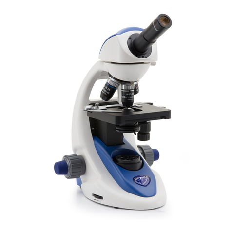
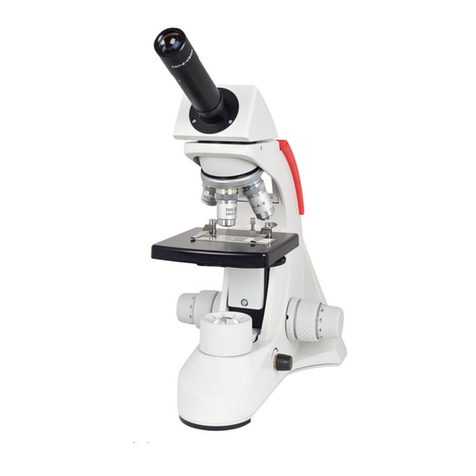
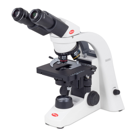
Vision Engineering DX41 User manual

User Guide
Routine Laboratory Microscope

This manual is written for the routine laboratory microscope the
DX41.
We strongly recommended that you carefully read this manual before using the microscope to familiarise yourself
with its functions & controls, for best practice when using the DX41 and ultimately for your health & safety.
Contents
Maintenance - Page 3
Packing Contents - Page 4
Assembly
Assembly Diagram - Page 5
Installing the mechanical stage support device - Page 6
Installing the trinocular viewing unit - Page 7
Installing and replacing the lamp - Page 7
Installing the lamp housing - Page 7- 8
Installing the objectives - Page 9
Installing the eyepieces - Page 10
Installing the video port (optional) - Page 10
Adjustments
Adjustments of the DX41 Diagram - Page 11
Adjustments of the DX41 Diagram Cont. - Page 12
Operation
Turning on the lamp - Page 13
Adjusting the intensity - Page 13
Adjusting the Tension Adjustment Collar - Page 13
Adjusting the interpupillary distance - Page 14
Adjusting the Dioptre - Page 14
Focusing - Page 15
Adjusting the Swing-out Condenser - Page 15
Using the Swing-out Condenser - Page 16
Adjusting the Aperture Diaphragm - Page 16
Adjusting the Field Diaphragm - Page 17
Switching the Light Path Selection - Page 17
Technical Specifications
Technical Specifications - Page 18
Warranty
Warranty - Page 19
1
www.visionbiomed.com Routine Laboratory Microscope

DX41 Routine Laboratory Microscope
Safety notes
1. Carefully open the box, taking care not to damage any of the delicate accessories like the lenses.
2. Keep the instrument out of direct sunlight, high temperature or humidity, and dusty & dirty environments.
Make sure the stage is placed on a smooth, horizontal and even surface.
3. When moving the instrument, please use both hands to grip the two sides of the microscope's body.
4. If the bacterium solution or water splash onto the stage, objective or viewing tube, turn off the microscope
at the mains immediately and wipe the microscope using the soft cloth provided (preventing any damage to
the DX41).
5. When the DX41 is in use, the lamp housing and nearby parts will be very hot. Please ensure there is
enough room surrounding them to enable them to cool down.
6. Make sure the instrument is earthed, to avoid any electric shocks.
7. For your safety, make sure the main switch is off (“O”) before replacing the halogen lamp or the fuse. Turn
the power off, and perform the operation after the lamp bulb and the lamp house are completely cool.
8. Check the input voltage: make sure the input voltage which is marked on the back of the microscope is
consistent with the power supply voltage otherwise, it will cause serious damage to the instrument.
9. Please use the power cord supplied.
2
www.visionbiomed.com Routine Laboratory Microscope

Maintenance
1. All the lenses have been thoroughly checked and adjusted - do not try and disassemble them yourself!
2. The nosepiece and coarse/fine focus unit have a compact and precise frame. Please don’t disassemble
them.
3. Keep the instrument clean by wiping dust regularly and avoid contaminating the optical elements.
4. Contamination on the prism, like finger prints and smears, can be gently wiped with a piece of soft cloth or
gauze which has been immersed in pure alcohol or xylene*. *(note that the alcohol and the xylene are
flammable, avoid using near direct heat).
5. Do not use an abrasive solvent to wipe the non-optical elements, use a soft detergent only.
6. If the microscope is splashed by any form of liquid, turn off the power immediately, and wipe up the
moisture.
7. Do not disassemble any part of the microscope. This will affect the function and the performance of the
microscope.
8. Place the instrument in a cool, dry position. After using the microscope, remember to cover it with dust
cover. Wait for the lamp housing to cool completely before covering.
3
www.visionbiomed.com Routine Laboratory Microscope

Packing Contents
1. Eyepiece (Ocular)
2. Video Port (optional)
3. Trinoclular Viewing Unit
4. Nosepiece
5. Objective
6. Mechanical Stage
7. Lamp Housing
8. Microscope Body
4
www.visionbiomed.com Routine Laboratory Microscope
Eyepiece (Ocular)
Video Port (optional)
Trinocular Viewing Unit
Lamp housing
Microscope body
Mechanical Stage
Objective
Nosepiece

Assembly
Assembly Diagram
The following diagram shows the assembly
sequence of the components.
The number in the figure shows the assembly steps.
Before assembling, make sure every component is
clean and be careful not to scratch any of the parts or
glass surfaces.
Keep the hexagon wrench
(supplied) in a safe place.
If you plan to change any of
the components in the
future, you will need
it again!
5
www.visionbiomed.com Routine Laboratory Microscope

Installing the
Mechanical Stage
Support Device
Before installing the device, make sure
you adjust the coarse focus knob.
Turn the guide board (see figure 1) down
to the lowest position so you can install
the mechanical stage support device
easily.
Hold onto the mechanical stage support
device (figure 2), place it on the top of
the guide board (figure 1), let the device
(figure 2) fall freely until it reaches the
limit position.
Use the hexagon wrench screw down
the locking block making sure the stage
support device (figure 1) and the guide
board are fixed together.
The mechanical stage has been
adjusted horizontally and fixed together
before leaving the factory.
* Do not disassemble unless it is
absolutely necessary, it may affect the
observation precision of the instrument.
6
www.visionbiomed.com Routine Laboratory Microscope

7
www.visionbiomed.com Routine Laboratory Microscope
Installing the Trinocular Viewing
Unit
Insert the trinocular viewing unit (figure 4) into the
microscope head (figure 5), turn it to an appropriate position,
then use the hexagon wrench to screw down the bolt (See
figure 5).
Installing and Replacing the Lamp
(figure 6)
Please use the specified halogen Lamp 6V/30 or 12V/50
1. Carefully hold the bulb with gauze or other
protective material, and gently insert the bulb into
the lamp holder until it is firmly in place.
2. When replacing the lamp, make sure the power is
turned off and the adapter is unplugged from
the mains.
* To prevent any injuries, make sure the microscope is cool
before performing any operation. Please insert the lamp
gently to prevent damage by excessive force.
* Do not touch the Halogen bulb with your hands, it will
shorten the service life or cause it to blow. If you leave any
finger marks on the surface, clean them off with a dry soft
cloth.
Installing the Lamp Housing
Keep the bolt on the lamp house (figure 6) in line with the
jack on the back of the microscope (see figure 7), then push
the lamp holder into the illumination kits gently, until they are
against each other (figure 8). 2-2-5
Lamp house
Bolt
Jack

8
www.visionbiomed.com Routine Laboratory Microscope

Installing the Objective
1. Adjust the coarse focus knob until the
support device of the mechanical stage
reaches its lowest limit position.
2. Reset the lowest magnification objective
onto the nosepiece from the left or the
right side (figure 9), then push the
nosepiece clockwise. Place the other
objectives assembling the lowest
magnification first and the highest last
(figure 10). Assembling the objectives in
this order will make switching between
objectives easier.
* Clean the objectives regularly, the objectives are
very sensitive to dust.
During operation, use the x10 magnification
objective for the initial focus and observation,
and then use a higher objective for more involved
tasks like dissection.
When replacing the objective, slowly turn the
nosepiece until you hear it click, this means the
objective is now secured in the correct position -
the light path centre.
9
www.visionbiomed.com Routine Laboratory Microscope

Installing the Eyepiece
Insert the eyepiece (figure 11) into the eyepiece tube, until they
are against each other. This is shown in the figure 14.
Installing the Video Port (optional)
Insert the video port (figure 12) into the trinocular unit (figure
13), then screw down the bolt to fix it in place - see figure 14.
10
www.visionbiomed.com Routine Laboratory Microscope

11
www.visionbiomed.com Routine Laboratory Microscope
Adjustments on the DX41
Condenser Focus Knob
Dioptre Ring
Locking Set

12
www.visionbiomed.com Routine Laboratory Microscope
Adjustments on the DX41 continued
Right Coarse
Adjustment
Knob
Right Fine
Adjustment
Knob
Brightness
Adjustment
Knob
Main Switch
Tension
Adjustment
Collar
Interpupillary
Distance
Indicator
Video Port
(optional)
Light Path
Selector
Lever
Swing out
Condenser
(with Aperture
Diaphragm)
Field Diaphragm
Stage Adjustment
Knobs

Operation
Turning on the Lamp (Figure 15)
Connect the power and turn on the main switch - see figure 15
Adjust the Brightness (Figure 16)
Turn the adjustment knob in Figure 16 clockwise to increase
the brightness. Turn the knob anticlockwise to decrease the
brightness
* Using the lamp on a low voltage, will prolong the life of the
lamp.
Adjusting the Tension Adjustment Collar (figure 17)
The tension adjustment collar has been set during the
manufacture of the DX41, if you find it’s loosening (the
mechanical stage might drop because of its heavy weight),
turn the tension adjustment collar until it is tight and securely
fastened.
* Be careful when changing the objective. If you finish the
observation with the short working distance objective, be
careful not to let the objective touch the specimen, if you
switch to a higher objective.
13
www.visionbiomed.com Routine Laboratory Microscope
Figure 15
Figure 16
Figure 17
Tension Adjustment Collar

Adjusting the Interpupillary Distance (Figure 19)
The interpupillary distance range: 48mm 75mm. When
observing with both eyes, hold onto the left and right prism
holders and turn the axis around. Adjust the interpupillary
distance until the left and right fields of view coincide.
Adjusting the Dioptre (Figure 20)
The right ocular tube is fixed. By turning the left dioptre ring
the operator can obtain a comfortable focus position with
both eyes.
14
www.visionbiomed.com Routine Laboratory Microscope
Figure 19
Figure 20

Focusing (figure 21, figure 22)
When the video set is not in use. Push in the light path
selector lever (figure 25) then observe with both eyes. Use
the x10 objective to focus and avoid touching the specimen
with the objective. Raise the mechanical stage slowly. The
operator can turn the coarse focus knob to get the specimen
broadly in focus and search in the x10 ocular
simultaneously, and then use the fine knob to focus
perfectly. At this moment, you can replace other objectives
safely, and focus without the risk of destroying the
specimen.
When using the video set, pull out the light path selector
lever (see figure 25), observe with both eyes, when the
image is sharp you can see the pictures directly on the
video screen, which connected by the microphotograph
system through to the video mount. If you need to fix the
stage on a vertical position to make the observation become
more convenient, use of the locking set.
Adjusting the Swing-out Condenser (Figure 23)
The centre of the condenser and the light axes of the
objective are coaxial. It has been adjusted before leaving
the factory so the users do not need to adjust them. The
highest position of the condenser has been adjusted too.
Turn the condenser focus knob to shift the condenser. The
condenser is raised when using the high magnification
objective, and declines when using the low magnification
objective.
15
www.visionbiomed.com Routine Laboratory Microscope

Using the Swing-out Condenser
When using a low magnification objective, swing the condenser out and let it swing away from the light path.
While using the high magnification objective, turn it into the light path.
Adjusting the Aperture Diaphragm
The aperture diaphragm is designed for the adjustment of the numerical aperture, not for the brightness. Generally,
reducing the diaphragm (opening to 70- 80% of the N.A.) value of the respective objective will provide an image of
acceptable quality. If you want to observe the image of the aperture diaphragm, remove one eyepiece and look
through the tube. You will see a dark circle encroaching at the bottom of the tube.
16
www.visionbiomed.com Routine Laboratory Microscope

Adjusting the Field Diaphragm (Figure 24)
The control for the field diaphragm is a ring used for
adjusting the area of field diaphragm. When using, turn the
ring to reduce the field diaphragm, look into the field and if
the diaphragm image is faint, perform the follow steps:
1. turn the condenser focus knob
2. shift the condenser holder to the position where the
observed image of the field of view is sharp
3. open the field diaphragm
4. let the image fill the field of view
5. reduce the mixed light, improving the quality of the
image.
Switching the Light Path Selection (Figure 25)
When the light path selector lever on the trinocular viewing
set is pushed in, all the light enters the binocular tube, so
you can do the binocular observation tube. While the lever
pull is out, some part of light enters the binocular tube, and
the rest enter the video tube, so you can observe through
the video equipment.
17
www.visionbiomed.com Routine Laboratory Microscope
Figure 25
Figure 24

Technical Specifications
Main specifications.
• Optical System Infinite Optical System Viewing Head Compensation Free
• Trinocular Head ,Inclined at 30º, Interpupillary distance: 48-75mm
• Eyepiece (Ocular) Exceed wide field ocular EW10X/22, tube 30 matched
• Nosepiece Backward Quintuple Nosepiece Objective
• Infinite plan Achromatic: x4 x10 x40 x100
• Focus System Coaxial Coarse and Fine Focusing System, Sensitivity and Graduation of Fine Focus:
0.001mm
• Stage Double layer mechanical stage, area: 185×142mm, movement range: 75×55mm
• Koehler Illumination Exposed illumination system, Aspheric collector, halogen lamp 6V30W
• Condenser Swing out condenser NA0.9/0.25
Configuration Table
• Viewing Head Compensation Free Trinocular Head
• Eyepiece Extra Wide Field Eyepiece
• Infinite plan objective: x4 x10 x40 x100
• Objective Infinite Plan Objective: x20 (Optional)
• Condenser Swing out Condenser NA0.9/0.25
• Video Accessories (optional)
• C Mount 1× Video Mount C Mount 0.5× (optional)
• Polarization Device (optional)
• Turret Phase Contrast Device (optional)
• Dark Field Device (optional)
• Fluorescent Attachment (optional)
• Temperature Control Device (optional)
Objective Specifications
Magnification
Numerical Value Aperture Diaphragm (N.A)
Working Distance mm
Thickness of Cover Slip Conjugate Distance mm
Magnification Sign (Colour loop)
18
www.visionbiomed.com Routine Laboratory Microscope

Warranty
This product is warranted to be free from defects in material and workmanship for a period of one year from the date of invoice to the original
purchaser.
If during the warranty period the product is found to be defective, it will be repaired or replaced at facilities of Vision Engineering or elsewhere,
all at the option of Vision Engineering. However, Vision Engineering reserves the right to refund the purchase price if it is unable to provide
replacement, and repair is not commercially practicable or cannot be timely made. Parts not of Vision Engineering manufacture carry only the
warranty of their manufacturer. Expendable components such as fuses carry no warranty.
This warranty does not cover damage in transit, damage caused by misuse, neglect, or carelessness, or damage resulting from either improper
servicing or modification by other than Vision Engineering approved service personnel. Further, this warranty does not cover any routine
maintenance work on the product described in the user guide or any minor maintenance work which is reasonably expected to be performed by
the purchaser.
No responsibility is assumed for unsatisfactory operating performance due to environmental conditions such as humidity, dust, corrosive
chemicals, deposition of oil or other foreign matter, spillage, or other conditions beyond the control of Vision Engineering.
Except as stated herein, Vision Engineering makes no other warranties, express or implied by law, whether for resale, fitness for a particular
purpose or otherwise. Further, Vision Engineering shall not under any circumstances be liable for incidental, consequential or other damages.
19
www.visionbiomed.com Routine Laboratory Microscope
Table of contents
Other Vision Engineering Microscope manuals
Vision Engineering
Vision Engineering TIM5 User manual
Vision Engineering
Vision Engineering SX25 User manual

Vision Engineering
Vision Engineering EVO Cam User manual
Vision Engineering
Vision Engineering Mantis User manual
Vision Engineering
Vision Engineering Mantis Compact User manual
Vision Engineering
Vision Engineering Mantis Elite User manual
Vision Engineering
Vision Engineering SX 45 User manual
Vision Engineering
Vision Engineering Mantis Troubleshooting guide
Vision Engineering
Vision Engineering Mantis Compact User manual
Vision Engineering
Vision Engineering MANTIS PIXO User manual
