VisionQuest DIY-4350 User manual

The specifications and information are subject to change without notice for quality improvement.
INSTRUCTION MANUAL
DIY-4350
4 Channel MPEG-4 Digital Vi eo Recor er
About this user gui e
Before installing and using this unit, please read this user guide carefully.
Be sure to keep it handy for later reference.

2
SAFETY PRECAUTIONS
EXPLANATION OF SYMBOLS
WARNING
To reduce a risk of fire or electric shock, do not expose this product to rain or moisture.
CAUTION
hanges or modifications not expressly approved by the manufacturer may void the user’s authority to
operate this equipment.
CAUTION
Danger of explosion if battery is incorrectly replaced.
Replace only with the same or equivalent type recommended by the manufacturer.
This symbol is intended to alert the user to the presence of important
operation and maintenance (servicing) instructions in the literature
accompanying the appliance.
This symbol is intended to alert the user to the presence of
unprotected “dangerous voltage” within the product’s enclosure that
may be strong enough to cause a risk of electric shock persons.

3
Do not use if the unit emits smoke, strange sounds are heard, or odor is emitted.
Make sure the power cable is not damaged.
Make sure there is no dust accumulation on the power plug or the outlet.
Disassembly prohibited
Do not place any foreign objects inside the unit.
Do not place a container holding water or other liquids above the unit when it is connected to power.
Do not allow the unit to get wet.
Do not use during thunder/thunder storms.
Do not place in an unstable position.
Do not expose to shock or vibration.
Do not use this unit in areas where it is exposed to the possibility of explosion.
Do not pull on the power cable when removing the power plug from the outlet.
Do not touch the power plug with wet hands.
Do not sit on.
Make sure the cables are connected properly.
Do not place heavy objects on connected units.
Never move this unit while the power is turned on.
Do not block the cooling fans or air ducts.
Do not expose to extreme temperatures or humidity changes.

4
Precautions for supplie AC A aptor
Never disassemble or modify.
Never get the adaptor wet.
Use only the supplied A adapter.
Do not connect to other appliances.
Do not connect this unit with the A adapter in areas reachable to children or where pets move
freely.
Never touch the A adapter with wet hands.
If the unit emits smoke, strange sounds or smells immediately remove the A adapter from the outlet.
Do not use during thunder/thunder storms.
Make sure the cable is connected properly.
Preventing damage to a cable

5
Main features of DIY-4350
- Real time monitoring at 30frames per channel (NTS ) / 25frames per channel (PAL)
- Recording speed at Maximum 30frames per channel (NTS ) / 25frames per channel (PAL)
- RJ45 connector for video input and camera power output help easy camera installation.
- Remote live monitoring and remote search/playback over network
- VGA video out and TV video out
- External IR receiver
Main replacement parts of DIY-4350
- Hard disk: 1 years (25° environment)
- ooling fan: 3 years (25° environment)
- Battery: 2 years (25° environment)
DVR set & Accessories
The package contains the main unit and its components as specified below. When you purchase the package,
please check to ensure the components specified below are included.
DVR Set
Remote ontroller
Battery1.5V (AAA x 2EA)
Adaptor and Power cable
lient Software D
User Guide

6
SPECIFICATIONS
INPUT 4 hanel RJ45 Module (NTS /PAL) – 1.0Vp-p composite, 75ohms
1 hanel R A (NTS /PAL) – 1.0Vp-p composite, 75ohms
VIDEO
OUTPUT (Selectable)
1 VGA
ALARM INPUT & OUTPUT 4 & 1
OS RTOS
OMPRESSION MPEG-4
VIDEO FORMAT NTS PAL
RESOLUTION &
RE ORDING SPEED
352x240/ H: MAX. 120fps/4 H
704X480/ H: MAX. 30fps/4 H
352x288/ H: MAX. 100fps/4 H
704X576/ H: MAX. 25fps/4 H
MODE Manual, Motion, Sensor, and Schedule
RE ORD
METHOD By Resolution, fps & Quality
MULTI TASK TRIPLEX Record, playback and transfer
ONTROL UNIT IR Type Remote ontrol & Front keys
DYNAMI IP Supported by DDNS
LAN PORT 1 10/100-base T Ethernet
NETWORK
FUN TIONS Live, Search & Playback, Backup, Setup
HDD APA ITY 1EA
NETWORK Still Image & Video data BA KUP
USB THUMB DRIVE
Still Image & Video data
ADAPTOR Input: A 100-240VA , 50/60Hz, 1.5A 200VA, Output: +12V 5A ELE TRONI AL
SPE IFI ATION
ONSUMPTION About 25W
TEMPERATURE 5° ~ 40°
HUMIDITY 30% ~ 90%
ENVIRONMENTAL
SPE IFI ATION
SIZE
DIMENSION 245(W) X 304(D) X 60(H)mm

7
INDEX
1. NAME & FUNCTION ....................................................................................................... 9
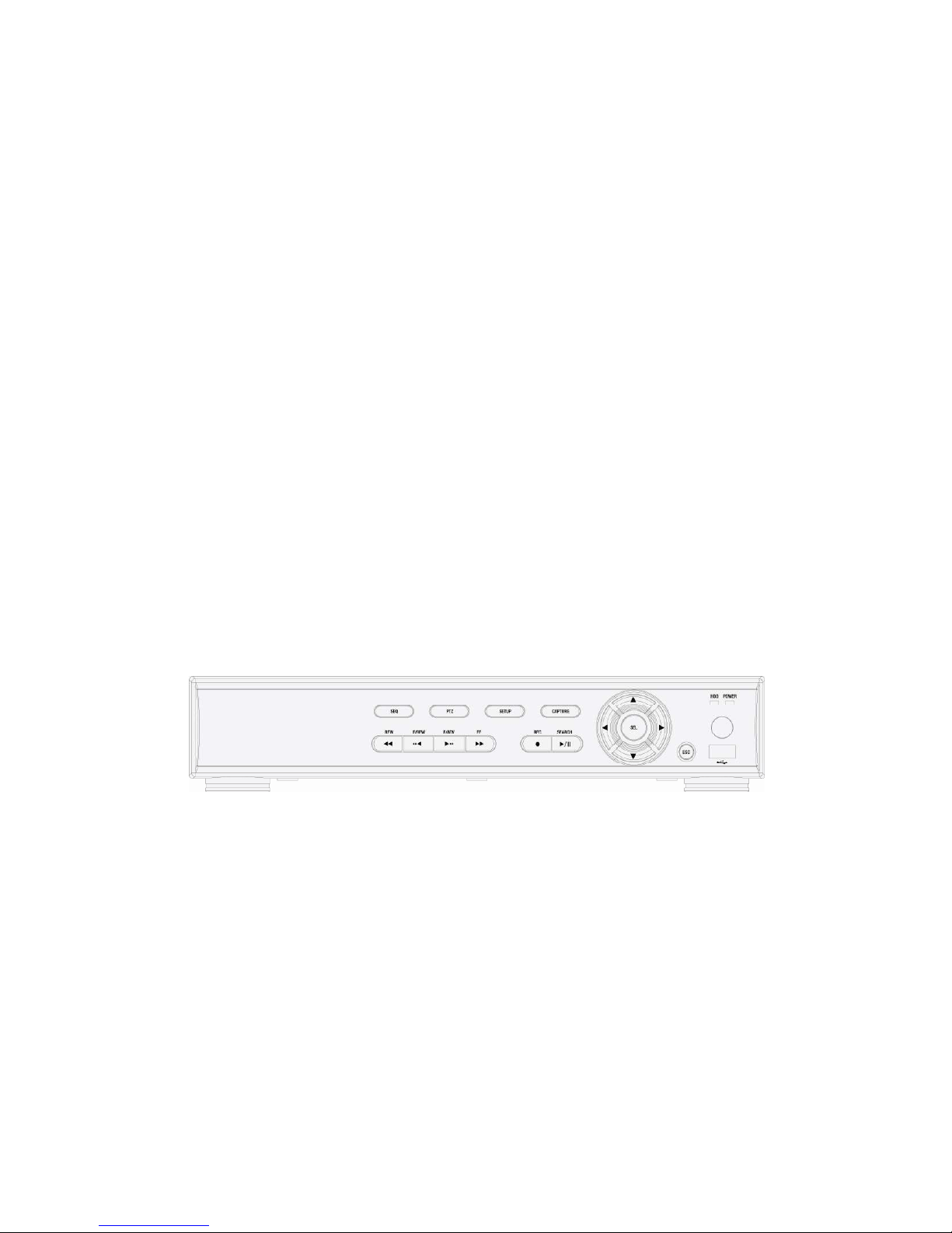
1-1. Front panel .................................................................................................................................................9
1-2. Remote controller.................................................................................................................................... 10
1-3. Rear panel an connection..................................................................................................................... 11
2. PREPARATION ............................................................................................................. 14
2-1. Selecting the type of monitor (TV monitor an VGA monitor)............................................................14
2-2. Live screen...............................................................................................................................................15
2-3. Time setting .............................................................................................................................................16
2-4. DLS (Day Light Saving) time setting: Summer time setting ...............................................................17
3. OPERATION - RECORD ............................................................................................... 18
3-1. MOTION DETECTION recor ing.............................................................................................................19
3-2. CONTINOUS recor ing ...........................................................................................................................20
3-3. SENSOR recor ing..................................................................................................................................20
3-4. Manual recor ing..................................................................................................................................... 21
3-5. SCHEDULE recor ing .............................................................................................................................21
4. OPERATION - PLAYBACK ........................................................................................... 24
4-1. EVENT SEARCH ......................................................................................................................................25
4-2. TIMELINE SEARCH..................................................................................................................................26
4-3. GO TO .......................................................................................................................................................27
4-4. GO FIRST..................................................................................................................................................27
4-5. GO LAST...................................................................................................................................................27
4-6. LOG...........................................................................................................................................................27

8
4-7. ARCHIVE................................................................................................................................................... 28
5. OPERATION - BACKUP TO USB THUMB DRIVE ....................................................... 29
5-1. Archiving an backup Still image in Live mo e................................................................................... 30
5-2. Archiving an backup Still image or Vi eo in Playback mo e...........................................................31
5-3. Backup Still image or Vi eo from ARCHIVE menu ..............................................................................32
5-4. Playback of AVI or DVR (Exclusive vi eo format) vi eo backup ata ............................................... 34
6. SETUP........................................................................................................................... 35
6-1. LIVE...........................................................................................................................................................36
6-2. RECORD ...................................................................................................................................................38
6-3. SYSTEM....................................................................................................................................................40
6-4. NETWORK ................................................................................................................................................42
6-5. STORAGE................................................................................................................................................. 45
6. NETWORK ACCESS USING THE EXCLUSIVE NETWORK VIEWER ........................ 47
6-1. PC requirements...................................................................................................................................... 47
6-2. Installing the network viewer .................................................................................................................47
6-3. Live monitoring mo e an functions. ................................................................................................... 48
6-4. Remote search mo e an functions ..................................................................................................... 51
6-5. PC System configuration........................................................................................................................54
7. NETWORK ACCESS USING WEB-BROWSER NETWORK VIEWER......................... 58
APPENDIX: HOW TO CONNECT NETWORK.................................................................. 60
A. How to set IP address of the DVR and open T P port of the router?...................................................... 60
B. How to access DVR from Remote P ?.................................................................................................... 62

9
1. NAME & FUNCTION
1-1. Front panel
① SEQ: To start auto sequencing of the screen in full screen mode. (Toggle)
② PTZ: To control PTZ operation (not working in this model.)
③ SETUP: To launch SETUP menu.
④ CAPTURE: To start operations of backup in live or playback mode.
⑤ SEARCH: To go to the search menu.
⑥ REC: To start and stop manual recording.
⑦ PLAY/PAUSE: To play or to pause the footage in playback mode.
⑧ REW: To rewind the footage at 1x, 2x, 4x, and 8x speed during playback.
⑨ F/REW : During playback - To move the playback position 60 seconds backward.
During pause - To move the playback position 1 frame backward.
⑩ F/ADV: During playback - To move the playback position 60 seconds forward.
During pause - To move the playback position moves 1 frame forward.
⑪ FF: To fast forward the footage at 1x, 2x, 4x, and 8x speeds during playback.
⑫ USB port: To connect USB Thumb drive to backup data.
⑬ HDD: The indicator blinks during recording and playback.
⑭ POWER: The indicator blinks when the A adaptor is connected.
Direction button
During setting
ⓐ To move the cursor Upward.
ⓑ To move the cursor to the Right or to change the setting values.
ⓒ To move the cursor Down.
ⓓ To move the cursor to the Left or to change the setting values.
During Live/playback & Entering passwor
ⓐ To select camera 1 or To enter No. 1
ⓑ To select camera 2 or To enter No. 2.
ⓒ To select camera 3 or To enter No. 3.
ⓓ To select camera 4 or To enter No. 4.
ⓔ To select full screen or quad screen view in live/playback or To select desired menu item or to store the setup value.
ⓕ To return to previous menu screen or To exit from playback.

10
1-2. Remote controller
① ID: When a remote control ID number is set in DVR, press it before number.
② REC: To start and stop manual recording.
③ Number: To select channel (1, 2, 3, & 4) or to enter DVR ID number.
④ F/REW: During playback - To move the playback position 60 seconds backward.
During pause - To move the playback position 1 frame backward.
⑤ F/ADV: During playback - To move the playback position 60 seconds forward.
During pause - To move the playback position moves 1 frame forward.
⑥ REW: To rewind the footage at 1x, 2x, 4x, and 8x speed during playback.
⑦ PLAY/PAUSE: To play or to pause the footage in playback mode.
⑧ FF: To fast forward the footage at 1x, 2x, 4x, and 8x speeds during playback.
⑨ Control button: Press to move the menu items or select channel.
⑩ SETUP: To launch SETUP menu.
⑪ SEARCH: To go to the search menu.
⑫ ESC: During setting - To return to previous menu screen.
During playback - To exit from playback.
⑬ BACKUP: To start operations of backup in live or playback mode. (The same function button as APTURE on the
front panel of DVR.)
⑭ SEQ: To start auto sequencing of the screen in full screen mode. (Toggle)
Operation range

11
1-3. Rear panel an connection
1-3-1. Basic connections
① ooling fan
② REMOTE IR: External IR receiver terminal
③ VIDEO IN: Video input terminal
④ VIDEO OUT: Video output terminal
⑤ VGA: VGA (Video Graphics Array) output terminal. onnects to the P VGA monitor.
⑥ ETHERNET: Network terminal
⑦ SENSOR IN: External sensor terminal
⑧ ALARM OUT: External alarm out terminal
⑨ VBS/VGA: System video output format switch
⑩ POWER: D 12V input terminal
Do not power this system on before all the connections are complete .
Make sure all the connections are properly. Faulty connection may result in the system being amage .
The DC plug of the AC a aptor is easy to be unplugge . Please make sure that the plug is remove .

12
1-3-2. Network connections
LAN Connection – Using the cross cable, without a switching hub
Connect to the system directly, using a cross type network cable
LAN Connection – Using a switching hub
Connect to the system, using a hub ( witching hub) and an Ethernet cable (10BA E-
T/100BA E-TX CAT 5 LAN cable)
Internet (ADSL) Connection
Connect to the system, using an Router or AD L modem and an Ethernet cable (10BA E-
T/100BA E-TX CAT 5 LAN cable)
Cross type cable
Switch ub
Router or ADSL modem
Internet

13
1-3-3. Sensor an alarm connections
SENSOR INPUT: onnect two signal lines of sensor (infrared ray sensor, heat perception sensor, magnetic
sensor) to the desired sensor number.
ALARM OUTPUT: Use Maximum current: 0.5A/125VAC, Maximum voltage: 1A/30VDC. When controlling
lamp and A operated equipment, control it using separate outside relay. During normal operation the control
output contact is maintained at “Open” status, and during control output the output contact is changed to
losed(short)” status.
Dried contact
Sensor
Alarm
Power
Source
NOTICE
SENSOR inputs need dried contact only. Do not input any electric signal.
---: Not operational
N/O: Normally open type sensor. When magnetic sensor is close , sensor sen s a signal.
N/C: Normally close type sensor. When magnetic sensor is opene , sensor sen s a signal.

14
2. PREPARATION
2-1. Selecting the type of monitor (TV monitor an VGA monitor)
2-1-1. VBS: Select VBS to connect general TV monitor
VGA: Select VGA to connect computer VGA monitor
The general TV monitor terminal an the computer VGA monitor terminal can not be use simultaneously.

15
2-2. Live screen
During the system is booting, “INITIALIZING” message is displayed. After the system booting is finished, the
video inputs from the cameras are displayed.
Various indicators showing the status of the DVR are shown as OSD symbols. These OSD and video display
can be hidden.
In icator Description
ontinuous recording in progress
Manual recording in progress
Sensor alarm recording in progress
Motion alarm recording in progress
Indicates that remote controller ID is set.
Indicates that motion is detected or sensor alarm input.
Indicates that alarm output is activated.
Indicates that a network client is connected to the DVR.
Indicates that sequencing mode is enabled.
Indicates the HDD is being recycled
Indicates the percentage of recorded data into HDD
If camera is not connecte or the connector is not properly connecte to vi eo input terminal, is
isplaye on the monitor.

16
2-3. Time setting
1. Press the SETUP button. Press Up arrow button four times to enter “1111” (Default password) and press
the SEL button. Then the SETUP screen is displayed. The password change is highly recommended to
avoid unauthorized usage.
2. Press the direction button to select the SYSTEM menu and press the SEL button.
3. Go to DATE FORMAT field using Up/Down arrow button and select the date format using Right/Left arrow
button.
4. Go to SET DATE & TIME field using Up/Down arrow button and press the SEL button.
5. Select the date and time that is be changed using Right/Left arrow button, change a value using Up/Down
arrow button, and press the SEL button. Then UPDATE DATE & TIME screen is displayed.
6. Select ONFIRM and press the SEL button. Then the system will reboot automatically showing
“INITIALIZING…” message.
The summer time is not applie on the factory efault time. When your country an territories is
un er summer time, DLS(SUMMER TIME) is to be applie .
YYYY/MM/DD (Ex. 2008/5/6
)
YYYY-MM-DD (Ex. 2008-05-06)
MM/DD/YYYY
MM-DD-YYYY
DD/MM/YYYY
DD-MM-YYYY

17
Setting in TIME MISMATCH
When the time of DVR is set earlier than the time of the last video data on HDD, the following message is
displayed.
Selecting “YES”: the video data between “SYSTEM TIME” and “HDD LAST TIME” will be deleted.
Selecting “GO TO TEST MODE”: Select only the video data between “SYSTEM TIME” and “HDD
LAST TIME” must not be deleted. Otherwise, do not select “GO TO TEST MODE”.
2-4. DLS (Day Light Saving) time setting: Summer time setting
1. Go to DLS field using Up/Down arrow button and select ON using Right/Left arrow button. Then the
summer time fields are displayed.
2. Select BEGIN field using Up/Down arrow button and press the SEL button. Then DLS BEGIN screen is
displayed.
3. Select the date and time that is be changed using Right/Left arrow button, change a value using
Up/Down arrow button, and press the SEL button.
4. After exit from BEGIN field setting, select END field using Up/Down arrow button and press the SEL
button. Then DLS BEGIN screen is displayed.
5. Select the date and time that is be changed using Right/Left arrow button, change a value using
Up/Down arrow button, and press the SEL button.
CAUTION:
-DLS can’t start from 23:00
-DLS can’t be applied, if the date of BEGIN and END is same.

18
3. OPERATION - RECORD
The system has 5 recoding modes.
MOTION DETE TION recording – Recording when the DVR detects motion form input video.
M icon is displayed on the screen. (Refer to page 19)
ONTINOUS recording – Recording continuously when the DVR is turned on.
icon is displayed on the screen. (Refer to page 20)
SENSOR recording – Recording when the external sensor of DVR is sett off.
S icon is displayed on the screen. (Refer to page 20)
Manual recording by RE button – Recording when the RE button of DVR is pressed.
R icon is displayed on the screen. (Refer to page 21)
S HEDULE recording – Recording according to the schedule setting. (Refer to page 21)

19
3-1. MOTION DETECTION recor ing
A motion detection setting is available for each channel.
① Set the basic record menu using the direction buttons before setting Motion detection.
RESOLUTION
HANNEL:
FRAME RATE
QUALITY
Upon Motion detection, the DVR records input video with these setting.
② To select a channel for motion detection recording, go to HANNEL filed using ▲▼ button and select a
channel from H1, H2, H3, and H4 using ▶◀ button.
③ Go to RE ORDING filed using ▲▼button and select BY MOTION using ▶◀button.
④ Go to MOTION ZONE filed using ▲▼button and select PARTIAL ZONE using ▶◀button.
⑤ Select the grids for motion detection using ▲▼▶◀button and SEL button. Then the selected grids are
displayed in Pink color.
⑥ Go to MOTION SENSITIVITY using ▲▼ button and select the sensitivity using ▶◀button.
⑦ Go to PRE RE ORD using ▲▼ button and select ON or OFF as necessary using ▶◀button.
⑧ Go to POST EVENT RE ORD using ▲▼ button and select the time as necessary using ▶◀button.
⑨ Repeat this step to set the other channel as necessary.
⑩ Go to SAVE SETUP using ES button and save the setting.
When FULL ZONE is selecte , the DVR etects a motion from whole vi eo screen. Set only MOTION
SENSITIVITY.
Sensitivity gra e: 1 –The highest sensitivity against motion
9 – The lowest sensitivity against motion
When PRE RECORD is ON, the DVR recor s 1 fps for 5 secon s before any motion etection.
The available POST EVENT RECORD time: 2 to 30 secon s.

20
3-2. CONTINOUS recor ing
ONTINOUS recoding setting is available for each channel. The DVR records automatically input video in
ONTINOUS recording mode as a factory default, unless RE ODING mode is changed.
① Set the basic record menu using ▲▼ ▶◀ buttons before setting Motion detection.
RESOLUTION
HANNEL
FRAME RATE
QUALITY
Upon connecting cameras, the DVR records input video displaying on the screen.
② To stop ONTINOUS recording of each channel, go to HANNEL filed using ▲▼ button and select a
channel from H1, H2, H3, and H4 using ▶◀ button.
③ Go to RE ORDING filed using ▲▼button and select DISABLE using ▶◀button.
3-3. SENSOR recor ing
Sensor is connected to each channel and be used a recording trigger.
① onnect a sensor to an sensor terminal on the rear of the DVR. (Refer to page 13)
② Set the basic record menu using ▲▼ ▶◀ buttons before setting Sensor recording.
RESOLUTION
HANNEL
FRAME RATE
QUALITY
Upon sensor sends a signal to the DVR, the DVR records input video displaying S on the screen.
③ To select a channel for sensor triggered recording, go to HANNEL filed using ▲▼ button and select a
channel from H1, H2, H3, and H4 using ▶◀ button.
④ Go to RE ORDING filed using ▲▼button and select BY SENSOR using ▶◀button.
⑤ Go to SENSOR TYPE using ▲▼ button and select the type of sensor using ▶◀button.
⑥ Go to PRE RE ORD using ▲▼ button and select ON or OFF as necessary using ▶◀button.
⑦ Go to POST EVENT RE ORD using ▲▼ button and select the time as necessary using ▶◀button.
Repeat this step to set the other channel as necessary.
Go to SAVE SETUP using ES button and save the setting.
Alarm time setting on activation of motion etection or sensor
When motion detection or sensor is activated, a relay signal triggers the external alarm device.
onnect an external alarm device to the alarm out terminal (Refer to page 13)
To select a channel for alarm output upon an activation of motion detection or sensor, go to HANNEL
filed using ▲▼ button and select a channel from H1, H2, H3, and H4 using button.
Go to ALARM filed using ▲▼button and select ON or OFF as necessary using button.
Go to ALARM DURATION using ▲▼ button and select the time as necessary using button.
Repeat this step to set the other channel as necessary.
Go to SAVE SETUP using ES button and save the setting.
Table of contents