Vislink HDT-1000 User manual

KAMELYON Series
HDT-1000
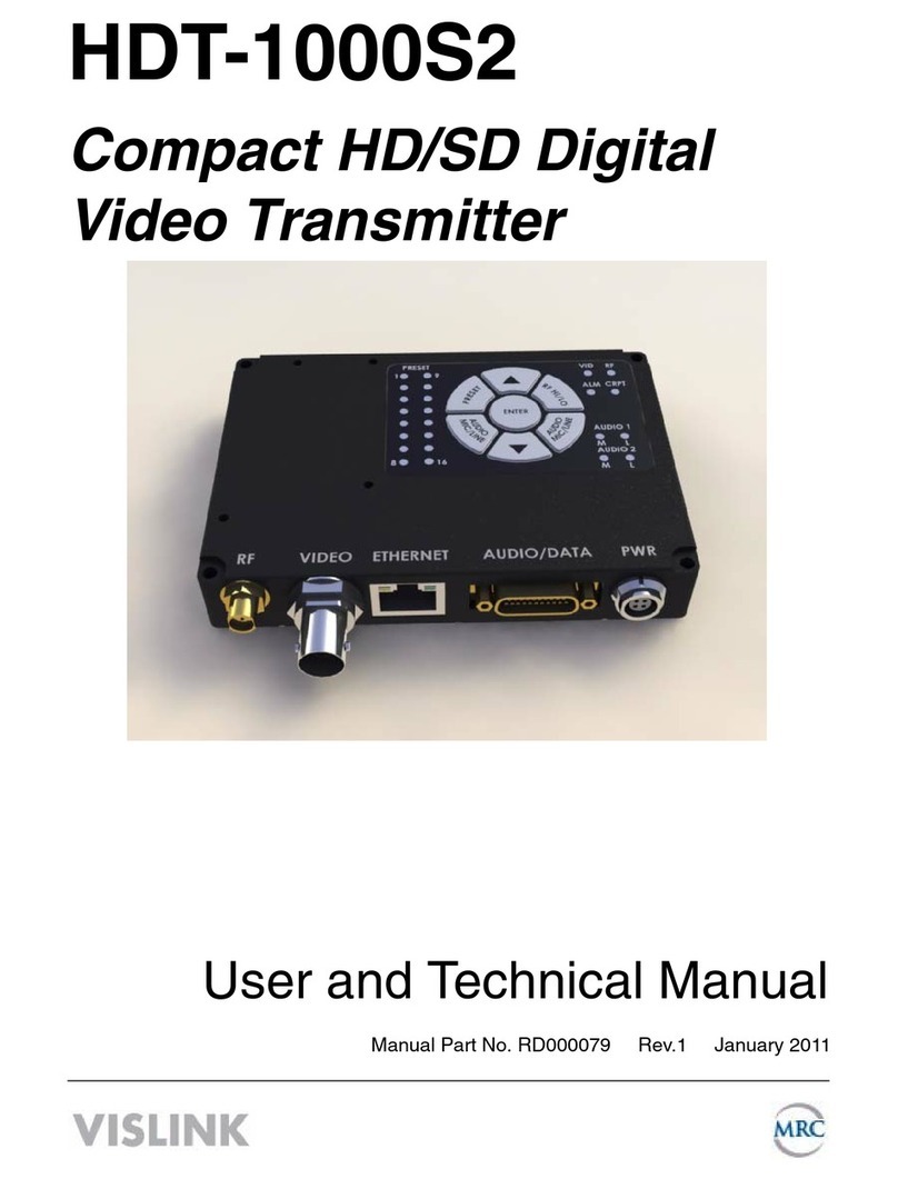
Compact HD/SD Digital
Video Transmitter
User and Technical Manual
Manual Part No. 400599-1 Rev. E March 2015

Page 2
HDT-1000 User and Technical Manual
Copyright © 2012
Part number 400599-1 Rev. E
Printed in U.S.A.
Authorized EU representative: Vislink PLC
Quality Certication Vislink is certied to ISO 9001:2008.
The Vislink trademark and other trademarks are registered trademarks in the United States and/or other countries.
Microsoft®, Windows®, and Internet Explorer® are registered trademarks of Microsoft Corporation in the United
States and/or other countries.
Proprietary Material The information and design contained within this manual was originated by and is the
property of Vislink. Vislink reserves all patent proprietary design, manufacturing, reproduction use, and sales rights
thereto, and to any articles disclosed therein, except to the extent rights are expressly granted to others. The
foregoing does not apply to vendor proprietary parts. Vislink has made every effort to ensure the accuracy of the
material contained in this manual at the time of printing. As specications, equipment, and this manual are subject
to change without notice, Vislink assumes no responsibility or liability whatsoever for any errors or inaccuracies that
may appear in this manual or for any decisions based on its use. This manual is supplied for information purposes
only and should not be construed as a commitment by Vislink. The information in this manual remains the property
of Vislink and may not be used, disclosed, or reproduced in any form whatsoever, without the prior written consent of
Vislink. Vislink reserves the right to make changes to equipment and specications of the product described in this
manual at any time without notice and without obligation to notify any person of such changes.
General Safety Information The following safety requirements, as well as local site requirements and regulations,
must be observed by personnel operating and maintaining the equipment covered by this manual to ensure
awareness of potential hazards. This equipment has been tested and found to comply with the limits for a Class
A digital device, pursuant to Part 15 of the FCC Rules. These limits are designed to provide reasonable protection
against harmful interference when the equipment is operated in a commercial environment. This equipment
generates, uses, and can radiate radio frequency energy. If not installed and used in accordance with the instruction
manual, it may cause harmful interference to radio communications. Operation of this equipment in a residential
area is likely to cause harmful interference in which case the user will be required to correct the interference at his
own expense.
About this Manual This manual is intended for use by qualied operators, installers, and service personnel. Users
of this manual should already be familiar with basic concepts of radio, video, and audio. For information about
terms in this manual, see Glossary of Terms and Abbreviations [Part No. 400576-1]. Pay special attention to Notes,
Cautions, and Warnings.
WARNING: General Warning.
Risk of Danger.
WARNING: Risk of Electric Shock.
CAUTION: Electrostatic Discharge.
Protective Earth Ground: Identies any
terminal intended for connection to an
external conductor for protection against
electric shock in case of a fault, or the
terminal on a protective earth electrode.
Frame or Chassis Ground Identies the frame
or chassis terminal.
Earth Ground: Identies the earth ground
terminal.
Fuse: Identies fuses or their location.
Waste Electrical and Electronic Equipment
(WEEE): The product must not be disposed
of with other waste. You must dispose of
the waste equipment by handing it over to a
designated collection point for recycling.
or
WARNING: RF power is present in the unit. Exposure to RF or microwave power
can cause burns and may be harmful to health. Remove power from the unit before
disconnecting any RF cables and before inspecting damaged cables and/or antennas.
Avoid standing in front of high gain antennas (such as a dish antenna) and never look
into the open end of a waveguide or cable where RF power may be present.
NOTE: Hazardous RF radiation limits and recommended distances may vary by
country. Ensure that all applicable state and federal regulations are observed when
using this transmitter.
The list below shows the Maximum Permissible Exposure [MPE] minimum safe distances from the
antenna. [FCC OET Bulletin 65, August 1997]
Antenna Gain 0 dBi 2 dBi 3 dBi 5 dBi 11 dBi
Safe Distance 4 cm 6 cm 6 cm 8 cm 15 cm
1.57 in 2.36 in 2.36 in 3.15 in 5.9 in

Page 3
HDT-1000 User and Technical Manual
Table of Contents
Quick Start .........................................................................................4
Introduction ........................................................................................5
Optional Accessories ...........................................................................................5
Band and Frequency Options............................................................6
Operation ...........................................................................................6
Antenna [SMA].....................................................................................................6
Video Input 1 [BNC] .............................................................................................6
Ethernet [Network RJ-45] ....................................................................................6
System I/O [Audio/Data 21-Pin]...........................................................................6
Power [Lemo].......................................................................................................6
Main Control Panel ..............................................................................................7
SAVE Button ........................................................................................................7
PRESET Button ...................................................................................................7
Control Operation Table.......................................................................................8
Audio Input Levels ...............................................................................................8
RF Output Power Level .......................................................................................8
Indicator LED Table .............................................................................................9
PC Network Setup ...........................................................................10
Web Browser Control Interface .......................................................12
Menu Bar ...........................................................................................................13
Change Password .............................................................................................13
Factory Settings.................................................................................................14
Streaming over IP ..............................................................................................15
Livestream .........................................................................................................16
Conguring Presets ...........................................................................................17
Presets - Recommended Encoder Settings ......................................................19
RangeMaster™..................................................................................................23
Firmware Upgrade .............................................................................................24
Board Information ..............................................................................................25
Comprehensive List of Web Browser Control Interface Features.....................26
Heatsinks .........................................................................................43
Connector Pin-Outs.........................................................................44
ANT 1 [RF Out SMA] .........................................................................................44
Video IN [BNC]...................................................................................................44
Ethernet [Network RJ-45] ..................................................................................44
Audio/Data [System I/O 21-Pin].........................................................................45
DC Power Input [4-Pin Lemo]............................................................................45
APPENDIX A. Find the IP Address of your Radio...........................46
APPENDIX B. DoubleVision™ ........................................................48
Transmitter Setup ..............................................................................................49
Receiver Setup ..................................................................................................51
Viewing Two Video Streams Simultaneously ....................................................52
Decoding two streams over IP using VLC.........................................................53
Specications...................................................................................54
Electrical ............................................................................................................54
Environmental....................................................................................................54
Mechanical.........................................................................................................54
Glossary...........................................................................................55
Notes ...............................................................................................60
Getting Support for Your Vislink Product .........................................61

Page 4
HDT-1000 User and Technical Manual
Quick Start
1. Connect your resonant antenna to suitable 50 Ohm SMA connector cable and
connect to transmitter ANT [RF Output] connector.
2. Connect your camera or other video signal source to suitable 75 Ohm BNC
connector cable and connect to transmitter Video 1 input connector.
3. Connect an Ethernet cable to the front panel RJ-45 ETHERNET connector and to
an available Ethernet Port on your Windows PC.
4. Connect the AUDIO/DATA System I/O cable Audio or MIC input connectors to
your audio equipment if you are planning to use audio.
5. Connect the RS-232 Data connector [System I/O] to your telemetry controller or
other device if you plan to transmit serial data.
6. Connect the RS-232 Control connector [System I/O] to your PC if you wish to use
serial link control.
7. Connect the DC Power In cable from your +11 - 32 VDC power source to the front
panel DC PWR connector. Allow 60 seconds for the transmitter to fully start-up.
NOTE: There is no ON/OFF Switch. Transmitter is ON when power is supplied.
8. Select your desired channel using the Preset and UP/Down buttons [see Main
Control Panel section]. Press the Save button.
9. If required, refer to Web Browser Control Interface section for Preset conguration
instructions. For special Livestream setup, see page 16.
DC
Power
Ethernet
to PC
Antenna
Video 1 RS-232
Control
RS-232
Data
Mic 1
Mic 2
Audio
1
Audio
2
B Video
System I/O
(Audio/Data)

Page 5
HDT-1000 User and Technical Manual
Introduction
The HDT-1000 compact HD/SD Digital Video Transmitter is designed for short-range,
portable and xed transmission applications. It transmits remote video to a central
receive location or streams video signals over Ethernet, Wi-Fi or cellular networks. It
has built in support to directly stream to various devices, Content Delivery Networks,
and direct setup connection for Livestream™. The HDT-1000 is designed to transmit up
to two NTSC or PAL standard denition [SD] video signals or one high-denition [HD]
video signal [up to 1080i] plus two audio signals and an RS-232 data channel. Common
uses include law enforcement surveillance and video collection.
The HDT-1000 transmits DVB-T COFDM digital signals consisting of either SD NTSC
or PAL or HD video formats. Vislink’s RangeMaster™ technology means narrowband
transmissions can travel up to four times the distance with very little degradation of
quality. The transmitter uses the H.264 MPEG video compression format for high-quality
imagery. DoubleVision™ technology allows for the transmission of two SD composite
video signals over a single link.
Control of the HDT-1000 is through a resilient membrane switch and indicator Main
Control Panel, located on the top of the unit. The control panel contains push buttons
and LEDs that allow the user to select presets and monitor system status. Use the Main
Control Panel to select from up to 16 individual preset congurations, which include
frequency, digital parameters and decryption code.
Optional Accessories
RF Cable
Heatsink
Antennas
Coax Video Cable
Encryption license

Page 6
HDT-1000 User and Technical Manual
Band and Frequency Options
HDT-1000 TX models are available for a variety of bands:
HDT-1000P P band 300—400 MHz
HDT-1000L L band 1.7—1.9 GHz
HDT-1000S S band 2.0—2.5 GHz
HDT-1000C1 C1 band 3.1—3.6 GHz
HDT-1000C2 C2 band 4.4—5.0 GHz
HDT-1000C3 C3 band 6.4-7.1 GHz
Unlicensed operation under FCC Part 15 in S Band is factory limited to 2.414 - 2.458
GHz. Check your model number for the operating band of your HDT-1000.
This device complies with part 15 of the FCC Rules. Operation is subject to the
following two conditions: [1] This device may not cause harmful interference, and [2] this
device must accept any interference received, including interference that may cause
undesired operation
Operation
Antenna [SMA]
Connects to SMA (female) connector cable [50 Ohm].
Provides RF output to antenna.
Video Input 1 [BNC]
Connects to 75 Ohm female BNC connector cable. Carries
video input from the camera/video source.
Ethernet [Network RJ-45]
Connects to RJ-45 connector. Supports web browser
control interface. It is also used for IP streaming data output.
System I/O [Audio/Data 21-Pin]
Connects to 21-pin System I/O connector [female]. Provides
audio in and RS-232 interconnections to [optional] telemetry
unit and/or Windows PC [for conguring channels].
Power [Lemo]
Connects to the 4-pin Lemo DC input cable. There is no
power switch on the unit; it operates when connected to DC
power.
Input Voltage: +10 to +32 VDC
Power Consumption: 10 W [nominal]

Page 7
HDT-1000 User and Technical Manual
Main Control Panel
The Main Control Panel is located on the top of the unit and
provides both controls and indicators. Selection of presets
along with selecting basic operational settings and viewing
alarms are all available on the Control Panel. The panel
contains an LED Dark Timer that turns OFF LEDs after a
10 second delay. All LEDs are momentarily activated when
the unit is rst powered ON.
SAVE Button
To save new settings including Audio Mic/Line and Preset,
you must press the SAVE Key to complete the task.
PRESET Button
The HDT-1000 has up to 16 pre-congured* PRESETS in
memory that include settings such as frequency and power
output mode. To select a Preset [1 - 16], complete the
following steps:
1. Press the PRESET key. The currently selected preset
LED illuminates.
2. Press the Up ▲or Down ▼arrow keys to choose the
new preset you want.
3. The preset LED illuminates to indicate which preset was
selected. Press SAVE to complete.
NOTE: The HDT-1000 recalls the most recently
saved audio input setting when it is powered up.
NOTE: If the SAVE key is not pressed within 5
seconds of the new setting, the audio input level
returns to the most recently used value and the
selection mode is canceled.
*PRESETS are congured using the Web Browser Control Interface.

Page 8
HDT-1000 User and Technical Manual
Audio Input Levels
To set audio input to MIC or LINE level*, complete the
following steps:
1. Press the AUDIO 1 MIC/LINE or AUDIO 2 MIC/LINE key.
The currently selected audio input LED illuminates.
2. Press AUDIO 1 MIC/LINE or AUDIO 2 MIC/LINE key
again to toggle between MIC or LINE input. The AUDIO
LED illuminates to indicate which audio input was
selected.
3. Press SAVE to complete.
NOTE: The HDT-1000 recalls the most recently
saved audio input setting when it is powered up.
NOTE: If the SAVE key is not pressed within 5
seconds of the new setting, the audio input level
returns to the most recently used value and the
selection mode is canceled.
RF Output Power Level
To set the RF Output Power Level, complete the following
steps:
1. Press the RF HI/LOW key to toggle power level.
2. Press SAVE to complete.
Control Operation Table
Button Description
RF HI/LOW Toggle between high and low power output.
▲Move UP through presets/levels.
▼Move DOWN through presets/levels.
AUDIO 1 MIC/LINE Press to select Audio 1 to Mic or Line then press SAVE to set.
AUDIO 2 MIC/LINE Press to select Audio 2 to Mic or Line then press SAVE to set.
PRESET Press to enter Preset mode. The PRESET LED indicates the current preset. Press
the UP ▲ or DOWN ▼ button to select one of the stored Presets [1 - 16]. Press
SAVE to conrm the new setting.
SAVE Conrms the new setting.
* Mic Gain can be increased in the Web Browser Control Interface. Select Presets > Video Settings
from the menu bar to display the Encoder Settings screen.

Page 9
HDT-1000 User and Technical Manual
Indicator LED Table
Indicator Description Suggested Actions
PRESET Displays the selected PRESET
[1 - 16].
Select the desired PRESET.
AUDIO Green when enabled. Dark when
disabled. M=MIC L=LINE
Select the desired AUDIO setting.
RF HI Green when radio power output is
set to high. Dark when set to low
power.
Select the power level required to optimize the
link.
VID Green when a valid video signal
is present. Dark when no valid
video signal is present. Valid
video can be NTSC or PAL analog
composite, as well as ASI or HD-
SDI digital signal.
Check the video camera/source and cabling
to ensure the video signal is reaching the
transmitter. The Signal has to match what preset
is selected and what is congured in that preset.
ALARM Red when an alarm occurs. Dark
when no alarm present.
Connect transmitter to PC via the Ethernet
interface to diagnose the source of the alarm.
CRYPTO Green indicates encryption
is enabled and transmitter is
transmitting the encryption code
associated with the preset. Dark
indicates encryption is disabled.
Verify whether encryption is required for the
selected preset.
Verify that encryption is properly congured.

Page 10
HDT-1000 User and Technical Manual
PC Network Setup
Before connecting to the radio using the Ethernet port on your Windows PC (via the
Web Browser Control Interface described in the next section) you must rst congure
your PC as described in the steps given below.
NOTE: Windows 7 is shown here. Other versions of Windows may vary slightly.
1. From Windows Control Panel, go to Network and Sharing Center.
2. Click on Change Adapter Settings.
3. Right click the Local Area Connection icon and select Properties.
The Network Connections window displays.

Page 11
HDT-1000 User and Technical Manual
4. The Local Area Connection Properties dialog box displays. Select Internet
Protocol Version 4 [TCP/IPv4]to highlight the item, then click the
Properties button.
5. The Internet Protocol Version 4 [TCP/IPv4]Properties dialogue box displays.
Enter the parameters shown below. Next, click the OK button.
This is the proper network setup
for connecting to your radio
via the Web Browser Control
Interface.
IP Address 192.168.1.1
Subnet Mask 255.255.255.0
Proceed to the Web Browser
Control Interface section.
NOTE: Close the Local
Area Connection Properties
dialogue box to complete.

Page 12
HDT-1000 User and Technical Manual
Web Browser Control Interface
The HDT-1000 has on-board rmware that enables web browser control without the
need to install software. To set-up PC control of your transmitter, complete the following
steps:
1. Connect an Ethernet network cable to the RJ-45 Ethernet connector on the front
panel of the HDT-1000 and to your PC.
2. Open a web browser and type [default address] 192.168.1.200 into the URL
address eld and press Enter. A login screen displays.
3. Enter your user name and password then click the Login button.
NOTE: The transmitter is factory programmed with the user name root and
password root. To avoid unauthorized access, the factory assigned password
should be changed by accessing the System > Password Change tab. See
Change Password section.
4. If the password to access the radio has been lost, the radio can be returned to
factory default settings.
WARNING: This will erase all presets, encryption keys, and other setings in
addition to setting the radio back to the default factory login and password.
This reset is done by simultaneously holding down the up, down, and preset keys
for 10 seconds. When the reset is done, the radio will go through its startup cycle,
indiating that the reset has taken place.
root
root
Write down your password information here.
Login
Password
Unit S/N

Page 13
HDT-1000 User and Technical Manual
Menu Bar
Navigating the Web Browser Control Interface is accomplished by clicking on a menu
option in the Menu Bar. For example, to go to the Change Password screen you would
navigate to System >Password Change as shown.
Change Password
The transmitter is factory programmed with the user name root and password root.
To avoid unauthorized access, the factory assigned password should be changed by
selecting System >Password Change from the menu bar.
Enter your new password in the New Password eld. The case sensitive password can
be up to 18 alphanumeric characters in length. Enter the new password in the Conrm
Password eld then click the Change Password button.
NOTE: Be sure to remember your new password.
menu bar

Page 14
HDT-1000 User and Technical Manual
Factory Settings
To access the Factory Settings screen, select System >Factory Settings on the menu
bar.
The Factory Settings screen is where you can read the Factory Settings directly from
your transmitter, as shown in the Device Mode section of the screen [above].
123456789

Page 15
HDT-1000 User and Technical Manual
Streaming over IP
The Factory Settings screen is also where you can set-up the transmitter to stream
over Ethernet. The Client IP Address, Protocol, Port, and Multicast TTL [Time To
Live] are set in the Transport Stream over Ethernet Settings section [bottom portion
of the Factory Settings screen].
You can then view the video stream using a client such as VLC Media Player [available
for free at http://www.videolan.org/vlc/].
NOTE: When streaming over IP, the transmitter does not simultaneously transmit
microwave RF.
192.168.1.1 Client IP Address must
match PC or other
device that you
are sending video to.

Page 16
HDT-1000 User and Technical Manual
Internet
Gateway
192.168.50.1
Transmitter
192.168.50.10
PC
Obtain an IP Address
Automatically (DHCP)
DC Power
To setup your HDT-1000 network for Livestream video broadcasting, complete the
following steps.
1. You must rst setup a Livestream account and have the login information handy.
2. Set your PC to Obtain an IP Address Automatically [DHCP].
3. Determine the IP address of your Gateway using Advanced IP Scanner if
necessary. We will assume the Gateway address is 192.168.50.1 for this example.
4. Set your Transmitter’s IP address to a number inside the same network as the
gateway. We will assume the Transmitter address is set to 192.168.50.10 for this
example.
5. Connect an Ethernet cable to the Transmitter’s front panel RJ-45 ETHERNET
connector and to your router or gateway device.
6. Connect a second Ethernet cable to an available Ethernet Port on your Windows
PC and to your router or gateway device.
7. Connect your camera or video source to the Video IN connector on the Transmitter.
8. Connect the AUDIO/DATA System I/O cable Audio or MIC input connectors to your
audio equipment if you are planning to use audio.
9. Connect the DC Power In cable from your +11 - 32 VDC power source to the front
panel DC PWR connector. Allow 60 seconds for the transmitter to fully start-up.
10. Navigate the Web Browser Control Interface to the Livestream page and congure.
Livestream
Go to www.livestream.com to
setup your free or premium account.
Go to pages 32-35 for Livestream
settings in the Web Browser Control
Interface

Page 17
HDT-1000 User and Technical Manual
Conguring Presets
To congure presets in your transmitter, complete the following steps:
1. To access the Presets screen, select Presets > View/Edit from the menu bar.
2. The Presets screen displays. Select the desired Preset Setting number to be
congured.
3. Click the Load button. The Web Browser Control Interface collects the current data
from the transmitter.

Page 18
HDT-1000 User and Technical Manual
4. To view the current data, select Presets >RF Settings from the menu bar.
5. The RF Band Settings screen displays the current Preset settings in the
transmitter. Make the desired changes to the preset such as RF Channel
Frequency [noting the 250 kHz step size] or Power Output Mode [High/Low].
6. Click the Apply button.
7. Finally, go back to Presets >View/Edit from the menu bar and on the Presets
screen, click the Store button to upload the new settings to your transmitter
NOTE: You MUST Store the data on the Presets screen to upload any changes to
the transmitter.
Decimal
Point
Frequency in MHz

Page 19
HDT-1000 User and Technical Manual
Presets - Recommended Encoder Settings
NOTE: Customizing Encoder Settings requires advanced knowledge of audio and
video systems and electronics. Typical application settings are presented in this
section.
To congure the Encoder Settings for a PRESET complete the following steps:
1. Select Presets >Video Settings from the menu bar near the top of the screen.
The Encoder Settings screen displays.
2. Use recommended settings listed in this section appropriate for your application.
Finally, go back to Presets > View/Edit from the menu bar and on the Presets
screen, click the Store button to upload the new settings to your transmitter
NOTE: You MUST Store the data on the Presets screen to upload any changes to
the transmitter.

Page 20
HDT-1000 User and Technical Manual
Standard Denition – Normal Delay
Video Settings
Input A Composite
Input B Disabled
Resolution 480i
Frame Rate Match Input
Output TS over Radio
Scale Factor No Scaling
H.264 Prole High
Slices 1 Slice per Frame
GOP Length 15
Standard Denition – Low Delay
Video Settings
Input A Composite
Input B Disabled
Resolution 480i
Frame Rate Match Input
Output TS over Radio
Scale Factor No Scaling
H.264 Prole High
Slices 1 Slice per Frame
GOP Length 0
Table of contents
Other Vislink Extender manuals

