ORiNG PET-102GT Plus Plus User manual
PET-102GT++
Quick Installation Guide
Version 1.0
Quick Installation Guide
PRINTED ON RECYCLED PAPER
QIG 1907-2-29-PET102GT++-1.0
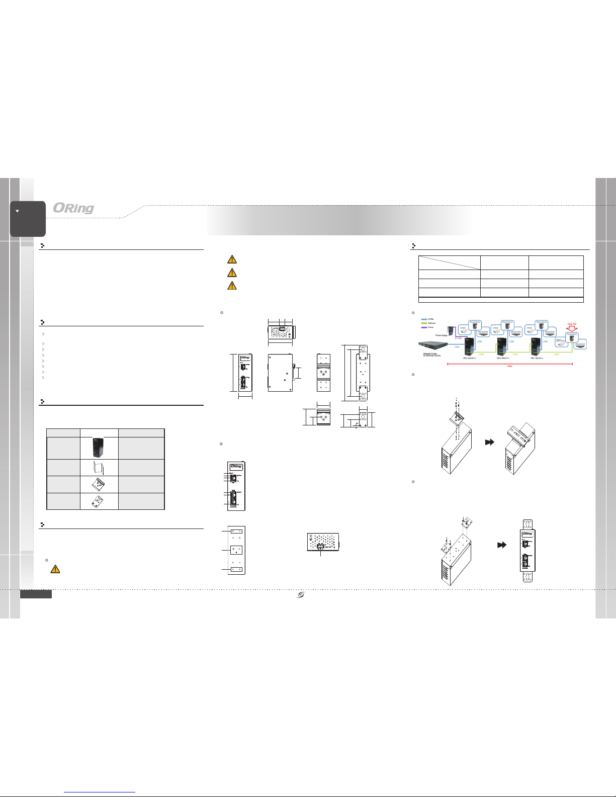
Installation and Distance
DIN-rail
Step 1 :
Step 2 :
Slant the device and screw the Din-rail kit onto the back of the device, right in the
middle of the back panel.
Slide the device onto a DIN-rail from the Din-rail kit and make sure the device clicks into
the rail firmly.
Dimension
Panel Layouts
Front Panel
1. Power LED
2. LNK/ACT indicator for P.D. port
3. P.D. port
4. PoE status LED for P.D port
5. LNK/ACT indicator for P.S.E. port
6. P.S.E. LED
7. PoE status LED for P.S.E port
1. Din-rail screw holes
2. Wall-mount screw holes
PET-102GT++
PET-102GT++
Introduction
The is a high power PoE extender and compatible with
IEEE802.3at/af standard. With one 10/100/1000TxBase-T(X) P.D. input port
and two 10/100/1000TxBase-T(X) P.S.E. output ports, the device can not only
deliver Ethernet data but also forward power from the previous PoE device
to the next device. Furthermore, the can be powered by
external DC power sources. By using external DC power to compensate for
power losses caused by long-haul transmission, users can continue to use
the PoE extender to enlarge the distance unlimitedly. With the ability to
provide 90Watts PoE power per port, the is surely a user-
friendly and high-power PoE extender.
PET-102GT++
PET-102GT++
PET-102GT++
Package Contents
The device is shipped with the following items. If any of these items is
missing or damaged, please contact your customer service representative
for assistance.
Contents
PET-102GT++
Pictures Number
X1
QIG X1
Preparation
Before installation, make sure you have all of the package contents
available and a PC with Microsoft Internet Explorer 6.0 or later, for using
web-based system management tools.
Elevated Operating Ambient: If installed in a closed environment, make sure
the operating ambient temperature is compatible with the maximum
ambient temperature (Tma) specified by the manufacturer.
Safety & Warnings
DIN-rail kit X1
Wall-Mount Kit X2
Rear Panel
1
Top Panel
1
1. Terminal block
Wall-mount
Extender
HIGH POWER POE++
INDUSTRIAL
Industrial High Power Extender
7
1
2
6
25.0
5.0
24.0
40.0
40.0
25.5
50.0
34.7 17.3 23.0
33.6
173.0
145.0
115.0
PET-102GT++
3
4
5
2
2
Step 1:
Step 2:
Step 3:
Screw the two pieces of wall-mount kits to the top and bottom panels of the device. A
total of screws are required, as shown below.
Use the device, with wall mount plates attached, as a guide to mark the correct locations
of the four screws.
Insert a screw head through middle of the keyhole-shaped aperture on the plate, and
then slide the device downwards. Tighten the screw head for added stability.
eight
Reduced Air Flow:
Mechanical Loading:
Circuit Overloading:
Make sure the amount of air flow required for safe operation of the
equipment is not compromised during installation.
Make sure the mounting of the equipment is not in a hazardous
condition due to uneven mechanical loading.
Consideration should be given to the connection of the equipment to
the supply circuit and the effect that overloading of the circuits might have on overcurrent
protection and supply wiring. Appropriate consideration of equipment nameplate ratings
should be used when addressing this concern.
Features
Support 1 port PoE P.D. input to 2 port POE P.S.E output with 10/100/1000Base-T(X)
for power and data extender
Supports P.S.E. based on IEEE 802.3af/at standard
PoE P.D. input support 90watts max.
PoE P.S.E. output support 90watts max. per port
Support auto-negotiation and auto-MDI/MDI-X
Multiple unit , daisy-chain installation support
High reliability and rigid IP-30 housing
DIN-Rail and wall mounting enabled
Power input on the first unit
P.D. attached on the last unit
50V DC 57 VDC
IEEE 80 2.3 at ( 25 .5 W) Extende d 2 un it
Max. Distance up to 300 meters
Extende d 3 un its
Max. Distance up to 400 meters
IEEE802.3af (12.95W) Extende d 4 un its
Max. Distance up to 500 meters
Extende d 5 un its
Max distance u p to 600 meters
NO P.D. on the last unit Extende d 5 un its
Max. Distance up to 600 meters
Extende d 6 un its
Max. Distance up to 700 meters
Note :T he t es t result is with one P.D. device connected to the last unit and on ly for reference.
Example for 57VDC power input and attached IEEE802.3at P.D.
PET-102GT++

QIG Quick Installation Guide
PRINTED ON RECYCLED PAPER
Quick Installation Guide
ORing Industrial Networking Corp.
Copyright© 2017 ORing
All rights reserved.
TEL: +886-2-2218-1066
FAX: +886-2-2218-1014
Website: www.oring-networking.com
E-mail: [email protected]
QIG
Version 1.0
10/100 Base-T(X)
Specifications
ORing Injector Model
RJ-45 Ethernet Port with P.D.
Input 1
Physical Ports
PET-102GT++
RJ-45 Ethernet Port with P.S.E.
Output
Operating Voltage
Input Voltage 50~57VDC
Output Power 90 Watts max per port(*Note)
Short Circuit protection Present
Over Load protection Present
Physical Characteristic
Enclosure IP-30
Dimension(WxDxH) 41(W) x 75 (D) x 115(H) mm (1.61 x 2.95 x 4.52 inch)
Weight (g)
Environmental
-40to80C(-40to176 F)
oo
Storage Temperature
5% to 95% Non-condensing
Operating Humidity
Regulatory Approvals
FCC Part 15, CISPR (EN55022) class A
EMI
EN61000-4-2 (ESD), EN61000-4-3 (RS), EN61000-4-4 (EFT), EN61000-4-5 (Surge),
EN61000-4-6 (CS), EN61000-4-8, EN61000-4-11
EMS
IEC60068-2-27
Shock
IEC60068-2-31
IEC60068-2-6
Vibration
Free Fall
Warranty
5 years
EN60950-1
Safety
-20to70C(-4to158 F)
oo
Operating Temperature
349 g
For pin assignments for different types of cables, please refer to the following tables.
PET-102GT++
PET-102GT++
Extender
HIGH POWER POE++
INDUSTRIAL
Industrial High Power Extender
RJ-45 Input (Data Only) RJ-45 Output (Data and Power)
Pin Sy mb ol Descrip tion Sy mbol Descrip tio n
1Rx+DataReceive
Rx+
(Vdc1+)
Data Re ceiv e an d
Feeding power(+)
2Rx-DataReceive
Rx-
(Vdc1+)
Data Re ceiv e an d
Feeding power(+)
3Tx+DataTransmit
Tx+
(Vdc1-)
Data Transmit an d
Feeding power(-)
4NCNotConnected
NC
(Vd c2+)
Not Connected
Feeding power(+)*
5NCNotConnected
NC
(Vd c2+)
Not Connected
Feeding power(+)*
6Tx-DataTransmit
Tx-
(Vdc1-)
Data Transmit an d
Feeding power(-)
7NCNotConnected
NC
(Vdc2-)
Not Connected
Feeding power(-)*
8NCNotConnected
NC
(Vdc2-)
Not Connected
Feeding power(-)*
RJ- 45 In put (Dat a Onl y) RJ-45 Outp ut (Dat a and Power )
Pin Symbol Description Symbol Description
1 B I_DA + Data BI_DA+ BI_DA+
(Vdc1+)
Data BI_DA+ and
Feeding Power(+)
2 BI_DA- Data BI_ DA- BI_DA-
(Vdc1+)
Data BI _DA- an d
Feeding Power(+)
3 B I_DB + Data BI_DB+ BI_DB+
(Vdc1-)
Data BI_DB+ and Feeding
Power(-)
4BI_DC+DataBI_DC+
BI_DC+
(Vdc2+)
Data BI_DC+
Feeding Power(+)*
5 BI_DC- Data BI_DC- BI_DC-
(Vdc2+)
Data BI _D C-
Feeding Power(+)*
6 BI_DB- Data BI_DB- BI_DB-
(Vdc1-)
Data BI_DB- an d
Feeding Power(-)
7BI_DD+DataBI_DD+
BI_DD+
(Vd c2-)
Data BI_DD +
Feeding Power(-)*
8 BI_DD - Data BI_DD- BI_DD-
(Vd c2-)
Data BI_DD-
Feeding Power(-)*
1000 Base-T
*: Only valid for PoE++ connection
Configurations
After installing the device and connecting cables, the green power LED
should turn on. Please refer to the following tablet for LED indication.
LED
Color
Status
Description
Power Green On DC power module activated
PoE I np ut
Green On Power is received
Amber On PoE input module activated
PoE Ou t pu t
Green O n Power is transmitted
Amber On PoE output module activated
2
Protection
Cable Types and Specifications:
Cable
Type
Max. Length
Connector
10BASE-T Cat. 3, 4, 5 10 0-ohm UTP 100 m (3 28 ft) RJ-45
100B ASE-TX Cat. 5 100-ohm UTP UTP 100 m (328 ft) RJ-45
1000BASE -T Cat. 5/Cat. 5e 1 00-ohm UTP UTP 100 m (328ft) RJ-45
*Note : LTPoE++ PSE technology is applied on this product. Only when an LTPoE++ Powered Device (PD)
is attached can the PSE port deliver up to 90W of output power.
TM TM
Network Connection
The device has three standard Ethernet ports. According to the link type, the device
uses CAT 3,4,5,5e UTP cables to connect to any other network devices (PCs, servers,
switches, routers, or hubs). Please refer to the following table for cable specifications.


