Siemens PAD-4 User manual

SiemensSiemens
SiemensSiemens
Siemens IndustryIndustry
IndustryIndustry
Industry,,
,,
,Inc.Inc.
Inc.Inc.
Inc.
BuildingBuilding
BuildingBuilding
Building
TT
TT
Tecec
ecec
echnologies Dihnologies Di
hnologies Dihnologies Di
hnologies Divisionvision
visionvision
vision
P/N 315-050217-4
Installation,Operation and Maintenance Manual
Model PAD-4
Distributed Power Module NAC Expander

Cyber security disclaimer
Siemens products and solutions provide security functions to ensure the secure operation of building comfort,
fire safety, security management and physical security systems. The security functions on these products and
solutions are important components of a comprehensive security concept.
It is, however, necessary to implement and maintain a comprehensive, state-of-the-art security concept that is
customized to individual security needs. Such a security concept may result in additional site-specific preventive
action to ensure that the building comfort, fire safety, security management or physical security system for your
site are operated in a secure manner. These measures may include, but are not limited to, separating networks,
physically protecting system components, user awareness programs, defense in depth, etc.
For additional information on building technology security and our offerings, contact your Siemens sales or
project department. We strongly recommend customers to follow our security advisories, which provide infor-
mation on the latest security threats, patches and other mitigation measures.
http://www.siemens.com/cert/en/cert-security-advisories.htm

i
Table of Contents
PREFACE................................................................................................................................. ii
1. DESCRIPTIONS.......................................................................................................................1
1.1 General Design Features .....................................................................................................1
1.2 Regulatory Standards ..........................................................................................................2
1.3 General Specifications .........................................................................................................2
2. INSTALLATION ........................................................................................................................5
2.1 Mounting the Enclosure .......................................................................................................5
2.2 Power Supply Mounting .......................................................................................................5
2.3 Control Unit Mounting ..........................................................................................................6
2.4 Wire Routing.........................................................................................................................6
2.5 Terminal Descriptions and Electrical Ratings ......................................................................7
2.6 Wiring The PAD-4 ................................................................................................................8
2.6.1 AC Wiring .............................................................................................................................9
2.6.1.1 Wiring from FP2011-U1/FP2012-U1 to PAD-4-MB............................................................10
2.6.2 Battery Connection.............................................................................................................11
2.6.2.1 Multiple Module Battery Connection ..................................................................................12
2.6.3 Class B (Style Y) Input/Output NAC Wiring .......................................................................13
2.6.4 Class A (Style Z) Input/Output NAC Wiring........................................................................14
2.6.5 Auxiliary Power Supply Output...........................................................................................15
2.6.6 Common Trouble Relay .....................................................................................................15
2.6.7 AC Fail Relay .....................................................................................................................16
2.7 Ground Fault Detection Enable/Disable.............................................................................17
2.8 Input Emulation ..................................................................................................................17
3. CONNECTION TO CONTROL UNITS ...................................................................................19
4. SAMPLE APPLICATIONS......................................................................................................33
4.1 Notification Appliance Power Applications......................................................................... 33
4.2 Door Holder Applications ...................................................................................................38
5. PROGRAMMING....................................................................................................................39
5.1 Dip Switch Settings ............................................................................................................39
5.1.1 Selecting the Input/Output Configuration ...........................................................................40
5.1.2 Setting the Auxiliary Output................................................................................................41
5.1.3 Setting the Input’s NAC Control .........................................................................................41
5.1.4 Setting the AC Power Fault Reporting Delay on the Global Trouble Relay.......................42
5.2 Jumper Settings .................................................................................................................42
6. REFERENCE DATA ...............................................................................................................43
6.1 Wire Selection Guides........................................................................................................43
6.1.1 Resistance of Solid Copper Wire .......................................................................................43
6.2 Battery Size Calculations ...................................................................................................44
7. COMPATIBLE DEVICES........................................................................................................45
8. TROUBLESHOOTING ...........................................................................................................45
8.1 LED Indicators....................................................................................................................45
8.2 Improper Operation ............................................................................................................46
8.3 Trouble Conditions .............................................................................................................46
9. BATTERY MAINTENANCE .................................................................................................... 47
10. GLOSSARY............................................................................................................................47
APPENDIX A: Compatible Legacy Devices For PAD-4 and PAD-4-CLSA ............................49

ii
PREFACE
Along with the use of this Owner’s Manual, the appropriate following standards and the manufacturers’
instructions for initiating and signaling devices should be used to install and maintain a functioning Fire
Alarm Signaling System.
NFPA 70 National Electrical Code
NFPA 72 National Fire Alarm Code
NFPA 101 Life Safety Code
C22.1 Part 1 Canadian Electrical Code
ULC-S524 Installation of Fire Alarm Systems
Other Standards - Contact the authority having jurisdiction for other standards that may apply.
For Publications, contact:
National Fire Protection Association
Batterymarch Park
Quincy, MA 022691

1
PAD-4 Installation, Operation and Maintenance Manual
1. DESCRIPTIONS
The Model PAD-4 from Siemens Industry, Inc. is a
notification and auxiliary power expander that
provides up to 9 amps of 24 volt DC for powering
notification appliances and auxiliary devices. The
PAD-4 provides its own AC power connection,
battery charging circuit, and battery connections.
Used with a fire alarm control unit, this enables
you to connect and distribute power to many more
devices than your control unit may normally allow.
1.1 GENERAL DESIGN FEATURES
Inputs
The PAD-4 has two optically isolated inputs that
provide the connection from the fire alarm control
unit notification appliance circuit to the PAD-4. The
inputs also provide a connection for returning a
trouble condition to the control unit notification
appliance circuit.
The fire alarm control unit supervises its notification
appliance circuit used for communicating with the
PAD-4 the same way it supervises ordinary NACs.
The inputs on the PAD-4 monitor the polarity of the
voltage coming from the fire alarm control unit’s
NACs to determine when to operate the notifica-
tion appliance circuit outputs. The PAD-4 emulates
the trouble behavior of a NAC by opening the EOL
supervision current for trouble conditions. Note
that the PAD-4 will sense the polarity of the fire
alarm control unit’s NACs to drive the outputs
whether or not the supervision connection is intact.
The following situations will open the EOL supervi-
sion at the inputs indicating a trouble condition:
• No or low AC power. For AC Fail reporting, refer to
Section 5.1.4 for configuration and response times.
• No and low battery condition.
• Ground fault to the output wiring.
• Auxiliary power supply output over-current
condition.
• NAC output open, shorted or over-current
condition on outputs associated with its input.
• Failure of the battery charger.
Notes:
If input 1 controls all four outputs, a fault on any output
will cause input 1 to indicate trouble. The fault does not
affect input 2.
If input 1 controls outputs 1 and 2, and input 2 controls
outputs 3 and 4, a fault condition on output 3 or 4 will
cause input 2 to indicate trouble. The fault does not
affect input 1.
Once the PAD-4’s inputs and outputs are activated, the
fire alarm control unit will not be able to sense trouble
conditions through its notification appliance circuit
connected to the PAD-4 input circuits. Use the PAD-4
trouble relay when it is necessary to monitor trouble
conditions and active alarm conditions at the same time.
Notification Appliance Circuit Outputs
The PAD-4 has four dedicated, power-limited, NAC
outputs that can be configured as two Class A
(Style Z) or four Class B (Style Y) circuits. An
additional two Class A (Style Z) circuits are
available when the PAD-4-CLSA module is in-
stalled.
The PAD-4 provides four configuration options
that will set the outputs as slaves that will follow
the input. If the inputs are on constant, they may
be configured as ANSI temporal code, Sync
strobe/horn operation or carbon monoxide (CO)
alarms.
Each of the four outputs is rated at 3 amps,
though a total of 6 amps maximum (or 9 amps
depending on power supply) can be drawn from
the PAD-4 outputs. The yellow Output LEDs
(DS1-DS4) flash to indicate an open, shorted or
over-current condition on its associated NAC
Output. The yellow Output LEDs are on steady to
indicate activation of the associated NAC output.
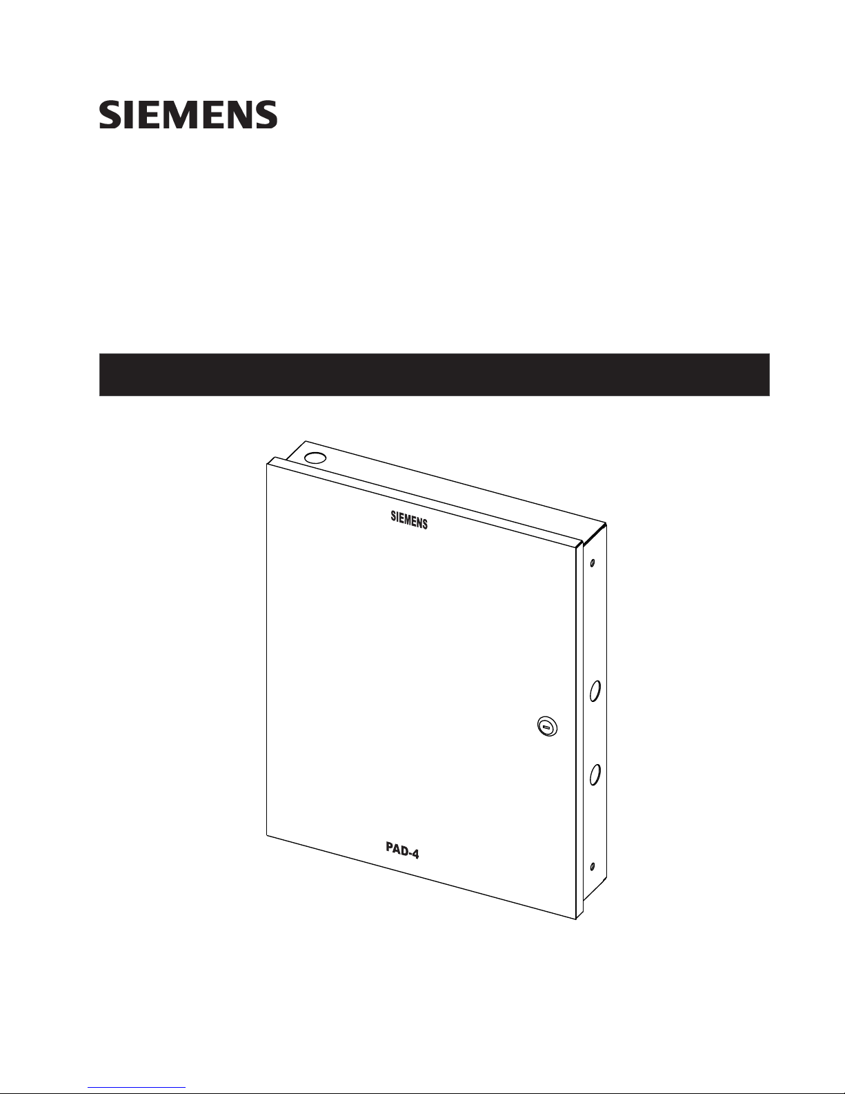
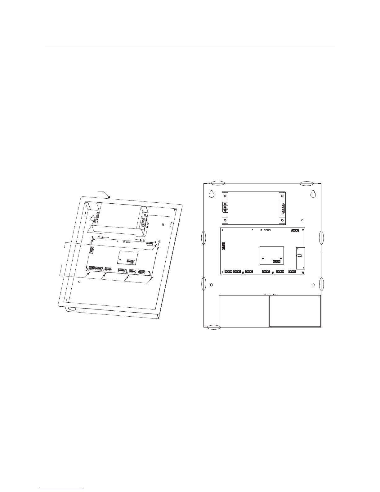
Selection of which input controls which output,
and which inputs are Class A (Style Z) and Class
B (Style Y) is done using the 10 position DIP
switch on the printed circuit board. Refer to
Section 5 for DIP switch settings.
The PAD-4-CLSA module, optional for UL installa-
tions but required for ULC installations, provides an
additional two Class A (Style Z) notification appli-
ance circuits to the PAD-4. When configured for
ULC operation, it also provides a Form A contact for
ground fault detection signaling. One PAD-4-CLSA
module can be mounted on the PAD-4. Refer to
P/N 315-050254 for more information.
Auxiliary Power Output
The PAD-4 has a dedicated, power limited,
auxiliary output that can be configured in two

2
PAD-4Installation, Operation and Maintenance Manual
different ways. The auxiliary output can either be
non-resettable (always on), or configured to
switch off when the AC power goes off to con-
serve the battery standby power. When the
auxiliary power is configured to switch off, there is
a 30-second delay before the auxiliary power is
turned off after the AC power goes off. The
auxiliary power is for supplementary purposes
only if it is configured to switch off when AC is lost.
The Auxiliary Power Output is rated at 3 amps. Only
a total of 6 amps maximum (or 9 amps depending
on power supply) can be drawn from the PAD-4
outputs. The yellow Aux PS LED (DS5) will flash to
indicate an over-current condition on the output.
The LED will go off if the battery conservation
feature is active.
Common Trouble Relay
The PAD-4 includes a Form C trouble relay that will
de-energize for the following trouble conditions:
• No or low AC power (Refer to Section 5.1.4
for delay time settings).
• No and low battery condition.
• Ground fault to the output wiring.
• Auxiliary power supply output over-current
condition.
• NAC output open, shorted and over-current
condition.
• Failure of the battery charger.
AC Fail Relay
A normally energized relay will be de-energized
after no or low AC power without delay. A Form A
contact provides a local signaling (audible and
visual) of an AC fail at the protected premises.
Battery Charging and Supervision
The PAD-4 provides a battery charging circuit for
charging sealed lead-acid batteries. The unit also
supervises for no and low battery conditions.
Battery Cutoff
In order to protect the batteries when AC fails, the
battery voltage is constantly monitored, and if it
drops below 20.4V, all PAD-4 power will be cut
off. Power will be restored when AC is restored.
Ground Fault Detection
The PAD-4 monitors for ground faults to the
output wiring. When detected, the unit lights the
yellow GRND LED (DS6) and de-energizes the
trouble relay and the input supervision relays. In
addition, in ULC configuration, the ground fault
relay on the PAD-4-CLSA module is also ener-
gized. Ground fault indication is common to all
output circuits and all NAC outputs are to be in
the same evacuation zone.
Environmental
All hardware is suitable for use only in an indoor,
dry environment.
Power Limiting
The AC power and battery wiring are not power
limited. All other circuits leaving the control unit
are power limited.
Transient Protection
Transient protection devices are provided where
needed to meet the requirements of UL864.
1.2 REGULATORY STANDARDS
The PAD-4 meets the requirements of industry
and government regulatory agencies as noted.
Federal Communications Commission
The PAD-4 meets the Class A requirements of
the Code of Federal Regulations (CFR 47), Part
15, subpart B, for electromagnetic field emissions.
Underwriters Laboratories
The PAD-4 control unit is listed under UL Standard
864 and UL 1481. It also complies with ULC
S527.
1.3 GENERAL SPECIFICATIONS
Operating specifications for the PAD-4 are as
follows:
Environmental
• Operating temperature
32 - 120°F (0 - 49°C)
• Relative humidity
Up to 93%RH @ 86°F (30°C) non-condensing

3
PAD-4 Installation, Operation and Maintenance Manual
• Installation Environment
Indoor, dry
Primary Supply Using FP2011-U1 External
Power Supply
• Primary Input Voltage: 120VAC/240VAC,
50Hz/60Hz
Primary Supply Using FP2012-U1 External
Power Supply
• Primary Input Voltage: 120VAC/240VAC,
50Hz/60Hz
Secondary and Trouble Power Supply
• 24 volt lead-acid battery set
• Maximum Charge Voltage: 29.0 VDC
• Maximum Charge Current: 1.5A
• Maximum Input Current: 15.3A
• Battery capacity: up to 18 A.H. (See Section
6.2, Battery Size Calculation, when using
batteries over 7 A.H.)
Input Circuits
• Two Input Circuits
• Connected to power limited source
• Supervised
• Voltage Range: 24 VDC nominal
• Maximum Input Current: 7.0mA
Notification Appliance Circuits
• Operating Voltage Range: Special Application
24 VDC
Refer to Siemens Compatible Notification
Appliances (P/N 315-096363) or Faraday
Compatible Notification Appliances (P/N 315-
096363FA), as applicable, for maximum
number per NAC
• Synchronized appliances permitted
• Maximum Alarm Current: 3.0A per circuit
(6.0A, or 9.0A depending on external power
supply, total for NACs and auxiliary power)
• Four Class B (Style Y) circuits or two Class A
(Style Z) circuits. Two additional Class A (Style
Z) circuits are available when the PAD-4-
CLSA module is installed.
• Power limited
• Supervised
• Maximum Standby Current: 1.0mA
• Maximum Ripple: 100mVAC
• Maximum Line Resistance:
3.0 ohms @ 3.0 amps
3.7 ohms @ 2.5 amps
4.7 ohms @ 2.0 amps
6.3 ohms @ 1.5 amps
• Maximum Voltage Drop: 9.0V
• Ground fault impedance: 60K ohms (+), 15K
ohms (-)
Auxiliary Power Output
• Operating Voltage Range: 24 VDC Special
Applications
• Current: 3 amps max (set to shutdown
when AC power fault for battery rating up
to 7.0 A.H.)
• Power limited
• Supervised for ground fault and short
• Maximum Ripple: 100mVAC
• Ground fault impedance: 2K ohms +/-
Note: The auxiliary power is for supple-
mentary purposes only if it is configured to
switch off when AC is lost.
Common Trouble Relay
• Contact Rating:
2.0A, 30VDC maximum, resistive
• Form C Contact
AC Fail Relay
• Contact Rating:
2.0A, 30VDC maximum, resistive
• Form A Contact (Normally closed, open on
fail)
Ground Fault Relay (on the PAD-4-CLSA
module)
• Contact Rating:
2.0A, 30VDC maximum, resistive
• Form A Contact (Normally open, closed on
fail)

4
PAD-4Installation, Operation and Maintenance Manual
This page is left intentionally blank.

5
PAD-4 Installation, Operation and Maintenance Manual
2. INSTALLATION
CAUTION:
It is recommended that the printed circuit
boards be removed for any procedure that
may cause dust, metal shavings, grease or
any such matter that may affect the circuit
boards and/or parts.
There may be several sources of power into
the control unit. Each source must be discon-
nected prior to installing or connecting or
disconnecting wiring.
Each output circuit is rated at 3 amps. DO
NOT OVERLOAD. Overloading a circuit will
cause it to shut down (power limit).
Minimum Configuration:
1. Enclosure, Model ENCL/DOOR PAD-4, P/N
500-050081
2. Power Supply, Model FP2011-U1, P/N 500-
450222 or Model FP2012-U1, P/N S54400-Z60-A1
3. PAD-4-MB, P/N 500-650217
4. 7AH or 18AH Batteries, P/N 175-387141 or
175-387194
5. Class A expansion module - model PAD-4-
CLSA, P/N 500-850254. Required for ULC
installations ONLY.
Optional Configuration:
1. Class A expansion module, Model PAD-4-
CLSA, P/N 500-850254. Optional for UL instal-
lations ONLY.
2. S3 Adaptor Plate, Model S3AP, P/N 500-650257
3. Battery Bracket, Model PAD-4-BATT-BRKT,
P/N S54430-B4-A1
2.1 MOUNTING THE ENCLOSURE
(For indoor use only in dry environments)
The fire alarm control unit must be mounted in a
properly accessible location as required by appli-
cable codes. Any auxiliary battery box or other
accessory not connected through a protective
device or a circuit designed for remote connection
must be within the same room and connected
through electrical conduit. Installation is to be done
only by qualified personnel who have thoroughly
read and understood these instructions.
When mounting the enclosure on interior walls,
use appropriate screw anchors in plaster. When
mounting on concrete, especially when moisture
is expected, first attach a piece of ¾-inch plywood
to the concrete surface. Attach the PAD-4-ENCL
enclosure to the plywood.
Consult the installation instructions, P/N 315-050081,
included with the enclosure for proper mounting.
2.2 POWER SUPPLY MOUNTING
Mount the PAD-4-ENCL enclosure to the wall
before mounting the FP2011-U1 or FP2012-U1
power supply to the enclosure.
1. Make sure that the dedicated circuit breaker
for the FP2011-U1 or FP2012-U1 is turned off
at the mains.
2. Place the housing for the FP2011-U1 or
FP2012-U1 over the four studs provided in
the upper left corner of the PAD-4 enclosure.
3. Secure the FP2011-U1 or FP2012-U1 to the
enclosure by slipping the lock nuts over the
four studs. Tighten them securely.
See Figure 2-1 and the FP2011-U1
Installation Instructions, P/N 315-050222, for
details, or Figure 2-2 and the FP2012-U1
Installation Instructions, P/N A6V10334250,
for details as applicable.
FP2011-U1
PAD-4-ENCL
FP2011-U1 Mounting
Studs (4 places)
FP2012-U1 Mounting
Studs (4 places)
Figure 2-1
Mounting the FP2011-U1
Figure 2-2
Mounting the FP2012-U1

6
PAD-4Installation, Operation and Maintenance Manual
2.3 CONTROL UNIT MOUNTING
PAD-4-MB is configured out of the box for ULC
operation. Remove jumper on J2 for UL installa-
tions. Leave jumper on J2 for ULC installations.
Refer to Figure 2-5 for location of this jumper. To
install the main board, install 4 screws loosely into
the 4 bottom mounting holes for the PAD-4-MB in
the enclosure. Slide the bottom of the board
behind the screws, aligning the screws with the
slots in the board. Install a screw in the top left
and top right corners of the main board. Tighten
all fasteners. All mounting hardware is included
with the PAD-4 main board. See Figure 2-3 below
for details.
PAD-4 Enclosure
PAD-4-MB
Mounting
6/32 x 1/4 screws
(6 places)
PAD-4-MB
TB10
FP2011-U1
FP2011-U1 Mounting
Studs (4 places)
Figure 2-3
Mounting the PAD-4-MB
2.4 WIRE ROUTING
Notes:
All high voltage and non-power limited wiring
must be kept separate from power limited
wiring. A ¼” separation must be maintained,
with high voltage and non-power limited
wiring running in separate conduit openings
from power wiring.
To avoid induced noise (transfer of electrical
energy from one wire to another), keep input
wiring isolated from high current output and
power-limited wiring. Improper wiring installa-
tion may cause improper operation. Avoid
pulling one multi-conductor cable for the
entire system. Instead, separate high current
input/output from low current.
Wiring within the cabinet should be routed
around the perimeter of the cabinet. It should
not cross the printed circuit board where it
could induce noise into the sensitive
microeletronics or pick up unwanted RF noise
from the switching power supply circuit.
A
B
C
D
E
F
G
A. Non-power Limited - High Voltage (AC power) or B
B. Non-power Limited - High Voltage (AC power) or A
C. Non-power Limited - Battery wiring, if separate
enclosure required) or D
D. Non-power Limited - Battery wiring, if separate
enclosure required) or C
E. Power Limited or F or G
F. Power Limited or E or G
G. Power Limited or E or F
Figure 2-4
PAD-4 Wire Routing

7
PAD-4 Installation, Operation and Maintenance Manual
2.5 TERMINAL DESCRIPTIONS AND ELECTRICAL RATINGS
Wire in accordance with the Authority Having Jurisdiction and Article 760 of the NEC NFPA 70 latest
edition and CEC.
To Connect External Wiring:
1. Loosen the screw of the terminal by turning it counterclockwise.
2. Insert the wire into the side of the terminal block.
3. Tighten the screw of the terminal block by turning it clockwise.
1-2ELBAT SNOITPIRCSEDLANIMRET4-DAP
lanimreTnoitpircseDsgnitaR
01BT
TUONRBtuonworB
ISSPtupnIlangiSylppuSrewoP
DNGdnuorGtiucriC.xamA9,lanimonCDV42
V42+NI_CD
11BT
+1)+(1tupnI
.xam
Am7,WFV/CDV42
-1)-(1tupnI *
11tupnI
+2)+(2tupnI
21BT
-2)-(2tupnI *.xamAm7,WFV/CDV42
22tupnI
MOCnommoC evitsiser,CDV03@A0.2 liaFCA
CNtcatnoCdesolCyllamroN
31BT
CNtcatnoCdesolCylla
mroN evitsiser,CDV03@A0.2 elbuorTlabolG
MOCnommoC
ONtcatnoCnepOyllamroN noitcennoCoN
41BT
+B1CAN)+(tuptuO1CAN
.x
amA3,CDV42,noitacilppAlaicepS
tuptuohcaehguohtnevE
eht,spma3rofdetarsi
morfwardtnerruclatot
dnastuptuoCAN
4eht
rewopyrailixuaeht
deecxetontsumtuptuo
1U-1102PFrofspma6
roylppusrewopW071
1U-2102PFrofspma9
ylppusrewo
pW003
-B1CAN)-(tuptuO1CAN
+B2CAN)+(tuptuO2CAN
.xamA3,CDV42,noitacilppAlaicepS
-B2CAN)-(tuptuO2CAN
51BT
+B3CAN)+
(tuptuO3CAN
.xamA3,CDV42,noitacilppAlaicepS
-B3CAN)-(tuptuO3CAN
+B4CAN)+(tuptuO4CAN
.xamA3,CDV42,noitacilpp
AlaicepS
-B4CAN)-(tuptuO4CAN
61BT
RWPXUA +YLPPUS )+(tuptuOrewoPyrailixuA .xamA3,noitacilppAlaicepS,CDV42
-YLP
PUSRWPXUA)-(tuptuOrewoPyrailixuA noitcennoCoN noitcennoCoN
*.lanimretwercsenorednusrotcudnocowtesu)-(2tupnI21BTdna)-(1tupnI11BTroF .egasurotcudnocelpitlumrofGWA22
-61seriuqerlanimretwercssihT
Terminal Blocks TB10 - TB16: 22 AWG Min., 12 AWG Max.

8
PAD-4Installation, Operation and Maintenance Manual
2.6 WIRING THE PAD-4
Remove all system power before installation, first battery and then AC. (To power up, connect the
AC first and then the battery.) Figure 2-5 shows the general layout of the PAD-4 main board. This
section also provides specific wiring details for accessories. Consult your control unit manual for specific
wiring information on the control unit being used. If you are using a Siemens control unit, see Section 3
for connections.
TB11
1+ 1- 2+
1
11
TB12 TB13 TB14 TB15
NAC3B NAC4B (NAC2A)
_
+_
+
NAC1B NAC2B (NAC1A)
_
+_
+
J4
NC COM NO
NC
COM
2- 2
1
J5
1
11
TB16
J8
AUX PWR SUPPLY
_
+
J7
P1
J2**
S2
JP7
DS7
BAT
DS5
AUX/PS
DS8
PWR
DS6 DS1
OUT1
DS2
OUT2
DS3
OUT3
DS4
OUT4
J9
TB10
J10
J12
J14
J13
J11
RESET
10987654321
ON
S1
J3
P2
SERVICE
PORT
J6
J16
NOT
USED
TROUBLE
1
B-
B+
INPUT 1 INPUT 2
DS11
BUSY
BRNOUT PSSI GND +24V
170W 10A
300W 20A
J1*
*J1 - Set Jumper J1 to 2-3 for normal operation
**J2 - Must be installed for Canadian installations. Must be removed for UL installations
Figure 2-5
PAD-4-MB Layout

9
PAD-4 Installation, Operation and Maintenance Manual
2.6.1 AC Wiring
AVANT ENTRETIEN
DESACTIVEZ L'UNITE
REMOVING
TERMINAL
BLOCK PROTECTION
DISCONNECT POWER
PRIOR TO
WARNING
FP2011-U1
AC
MAINS
BLACK (L)
WHITE (N)
GREEN (G)
NOTE: BRANCH CURRENT
MUST BE PROTECTED BY A
15A MINIMUM OVERCURREN
T
DEVICE.
S
UPERVI
S
ED
NON-POWER
LIMITED
12-14 AWG MIN.
USER-SUPPLIED 12-14 AWG
WIRE FROM GROUND
LUG TO FP2011-U1
GROUND LUG
IN PAD-4-ENCL
(TO CONNECT
GROUND WIRE
FROM AC MAINS)
CAUTION: INSTALL PLASTIC GUARD ON
AC MAINS
(
L, N, G
)
Figure 2-6a
AC Wiring to FP2011-U1
FP2012-U1
BLACK (H)
WHITE (N)
GREEN (G)
AC
MAINS
SUPERVISED
NON-POWER
LIMITED
12-14 AWG MIN.
CAUTION: INSTALL PLASTIC GUARDS ON
AC MAINS
(
H, N, G
)
USER-SUPPLIED 12-14 AWG
WIRE FROM GROUND
LUG TO FP2012-U1
GROUND LUG
IN PAD-4-ENCL
(TO CONNECT
GROUND WIRE
FROM AC MAINS)
NOTE: BRANCH CURRENT
MUST BE PROTECTED BY A
15A MINIMUM OVERCURRENT
DEVICE
Figure 2-6b
AC Wiring to FP2012-U1

10
PAD-4Installation, Operation and Maintenance Manual
2.6.1.1 Wiring from FP2011-U1 and
FP2012-U1 toPAD-4-MB
FP2011-U1
TB10
+24V (Red)
(Blk)
Brownout
(Blue)
GND (Blk)
PSSI
PAD-4-MB
SEE FIGURE 2-6a
FOR WIRING
LNG
AVANT ENTRETIEN
DESACTIVEZ L'UNITE
REMOVING
TERMINAL
BLOCK PROTECTION
DISCONNECT POWER
PRIOR TO
WARNING
Brownout PSSI GND +24V
170W
J3
300W 170W
J3
300W
Figure 2-7a
Wiring from FP2011-U1 Power Supply to PAD-4-MB
FP2012-U1
H
N
G
SEE FIGURE 2-6b
FOR WIRING
1234
TB10
PAD-4-MB
Brownout PSSI GND +24V
300W
J3
300W 170W
J3
170W
Figure 2-7b
Wiring from FP2012-U1 Power Supply to PAD-4-MB
NOTE:
1. Power Supply includes a cable
connection that is not
detachable.
2. Select 300W operation using
jumper on J3.
NOTE:
1. Power Supply includes a cable
connection that is detachable.
2. Select 170W operation using
jumper on J3.

11
PAD-4 Installation, Operation and Maintenance Manual
2.6.2 Battery Connection
The PAD-4 requires a 24V sealed lead-acid
battery set. The battery capacity can be from 7 to
18 A.H. For battery sets larger than 7 A.H., an
enclosure with System 3 rails or a separate listed
battery enclosure is required.
The following steps and diagram explain how to
connect the Siemens BT-33, 7 A.H. battery set to
the PAD-4-MB using the battery wires, P/N 600-
150217, included with the PAD-4-MB.
Make sure to connect AC power first
and then the battery.
1. Strip the insulation ¼” from the end of the red
and black battery wires.
2. Connect the red battery wire to B+, the
positive terminal of J6.
3. Connect the black battery wire to B-, the
negative terminal of J6.
4. Attach the quick disconnect end of the red
battery wire to the positive battery terminal.
5. Attach the quick disconnect end of the black
battery wire to the negative battery terminal.
6. Connect jumper wire from the positive (+)
side of battery #1 to the negative side of
battery #2.
When disconnecting the battery,
remove the quick disconnects from
the jumper wire, the black battery wire
and the red battery wire in that order.
The battery set is protected by a 10/20 amp,
32VDC replaceable AUTO-FUSE.
2-2ELBAT SNOITCENNOCYRETTAB4-DAP
lanimreT
6J
noitpircseDsgnitaR
+ByrettaB lanimonCDV42
-BdnuorGtiucriC
CAUTION:
MAKE SURE THAT THE QUICK
DISCONNECT END OF THE
BATTERY CABLE IS ATTACHED
TO THE CORRECT TERMINAL:
RED TO POSITIVE (+)
BLACK TO NEGATIVE
(
-
)
B+
B-
Figure 2-8
Battery Installation
1
JP7
DS8
PWR
J10
J3
P2
SERVICE
PORT
J6
J16
1
2
B-
B+
PAD-4-MB
J1
24V BATTERY SET
(7 TO 18.0 AH)
SUPERVISED
NON-POWER LIMITED
INPUT CURRENT (MAX.) 15.3A
CHARGE VOLTAGE (MAX.): 29 VDC
CHARGE CURRENT (MAX.): 1.5A
12 AWG
Figure 2-9
Battery Wiring to PAD-4-MB
3-2ELBAT SGNITARESUF61J4-DAP
ylppuSrewoPesuF
)W071(1U-1102PFA01
)W003(1U-2102PFA02
SEE
TABLE 2-3
FOR FUSE
RATINGS

12
PAD-4Installation, Operation and Maintenance Manual
2.6.2.1 Multiple Module Battery Connection
For applications where multiple PAD-4 boards are
mounted in an enclosure with System 3 rails, it
may be possible to connect two boards to a
single battery set. When using a single battery set
for two boards, the following rules must be
followed:
a) Both PAD-4 boards must be located within
the same enclosure and mounted adjacent to
each other.
b) The combined battery A.H. rating required for
both boards does not exceed 18 A.H.
c) Each PAD-4 and associated FP2011-U1
must be mounted on S3AP adapters. Refer to
the S3AP manual, P/N 315-050257.
d) One of the PAD-4 boards must have its
charging circuit disabled.
e) Two (2) battery connection splitters (part
number 230-299203) are used on the battery
set for proper connection.
The following steps and diagrams explain how to
connect two PAD-4 boards to a single battery set.
1. Install a battery connection splitter (see
Figure 2-10) to the positive and negative
terminals on the battery set. If the battery set
contains two 12-volt batteries to be wired in
series, install one splitter on the positive
terminal of battery #1 and the other to the
negative terminal of the battery #2.
2. Connect the black wires from both PAD-4
boards to the splitter on the negative terminal
of battery #2.
3. If the battery set contains two 12-volt
batteries, connect the jumper wire from the
remaining single positive terminal of battery
#2 to the negative terminal on battery #1.
4. Connect the red wires from both PAD-4
boards to the splitter on the positive terminal
of battery #1. See Figure 2-11.
5. Disable the battery charger on one of the
units. See Section 5.2 for directions.
Figure 2-10
Battery Connection Splitter
To PAD-4
To PAD-4
Figure 2-11
Dual Module Battery Connection
To each PAD-4
battery connection
terminal
To Battery Terminal

13
PAD-4 Installation, Operation and Maintenance Manual
2.6.3 Class B (Style Y) Input/Output NAC Wiring
Figure 2-12 shows how to wire for Class B (Style Y) input and output supervision. Use in/out wiring
methods for proper supervision.
Class B (Style Y) Output Notification Circuits
Figure 2-12 shows four, 1.5 amp devices wired as Class B (Style Y) circuits.
Place a 24K ohm EOL resistor (provided) at the end of each loop to enable notification output supervi-
sion when using all outputs as Class B (Style Y) notification circuits. The 24K EOLs must be wired to the
terminals whether or not you are using all output terminals.
Class B (Style Y) Supervised Input Circuits
Figure 2-12 shows Class B (Style Y) supervised wiring from a fire alarm control unit to the PAD-4 board.
Use the control unit’s EOL resistor installed as shown to enable notification input supervision. Note:
MIN: 22 AWG, MAX: 12 AWG.
TB11
1+ 1- 2+
1
11
TB12 TB13 TB14 TB15
NAC3B NAC4B (NAC2A)
_
+_
+
NAC1B NAC2B (NAC1A)
_
+_
+
NC COM NO
NC
COM
2- 2
11
11
TB16
AUX PWR SUPPLY
_
+
+
-
24VDC/VFW
7mA MAX.
SUPERVISED BY
FIRE ALARM
CONTROL UNIT,
POWER LIMITED
CLASS B (STYLE Y)
POLARITY SHOWN IN
ACTIVATED CONDITION.
NOTIFICATION OUTPUT
FROM FIRE PANEL
EOL
(SEE CONTROL UNIT
INSTALLATION INSTRUCTIONS)
FOR TB11 INPUT 1(-) AND
TB12 INPUT 2(-) USE TWO
CONDUCTORS UNDER
ONE SCREW TERMINAL.
THIS SCREW TERMINAL
REQUIRES 16-22 AWG
FOR MULTIPLE
CONDUCTOR USAGE.
-
+
+
-
24K, 1/2W
PART NO.
140-820405
NAC RATINGS:
ALARM VOLTAGE: 24VDC
MAX. ALARM CURRENT: 3A
MAX. RIPPLE: 0.1 VAC
MAX. STANDBY CURRENT: 1.0mA
NOTIFICATION APPLIANCE CIRCUIT
CLASS B (
SUPERVISED, POWER LIMITED
SEE SIEMENS P/N 315-096363 OR
FARADAY P/N 315-096363FA FOR
COMPATIBLE DEVICES
POLARITY SHOWN IN
ACTIVATED CONDITION.
STYLE Y)
DO NOT USE
DO NOT USE
DO NOT USE
INPUT 1 INPUT 2
-
+
+
-
-
+
+-
-
+
+
-
24K, 1/2W
PART NO.
140-820405
Figure 2-12
Class B (Style Y) Supervised Input/Output Connections

14
PAD-4Installation, Operation and Maintenance Manual
2.6.4 Class A (Style Z) Input/Output NAC Wiring
Figure 2-13 shows how to wire for Class A (Style Z) input and output supervision. Use in/out wiring
methods for proper supervision. Note: MIN: 22 AWG, MAX: 12 AWG.
Class A (Style Z) Output Notification Circuits
The configuration shown in Figure 2-13 shows two, 3-amp devices wired as Class A (Style Z) circuits.
When you are using the outputs as Class A (Style Z) circuits, loop the wiring back to the corresponding
circuit pair. For Class A (Style Z) wiring, no external EOL is necessary since it is built into the board.
PAD-4-CLSA Module
The PAD-4-CLSA module provides connectivity to two circuits wired as Class A (Style Z). Refer to the
PAD-4-CLSA Installation Instructions, P/N 315-050254, for more information.
Class A (Style Z) Supervised Input Circuits
The configuration shown in Figure 2-13 shows Class A (Style Z) supervised wiring from a fire alarm
control unit to the PAD-4 board. Pay close attention to the polarities when wiring the unit and follow
these requirements:
When wiring to terminal 1-, you must use two separate wires. Do not loop a single wire or twist two
conductor wires together.
Do not use notification appliances on Class A (Style Z) circuits connected for input. The PAD-4 will
detect voltage across the input circuits, but is not designed to pass the added current load from notifica-
tion appliances.
TB11
1+ 1- 2+
1
11
TB12 TB13 TB14 TB15
NAC3B NAC4B (NAC2A)
_
+_
+
NAC1B NAC2B (NAC1A)
_
+_
+
NC COM NO
NC
COM
2- 2
11
11
TB16
AUX PWR SUPPLY
_
+
DO NOT USE
DO NOT USE
DO NOT USE
NAC RATINGS:
ALARM VOLTAGE: 24VDC
MAX. ALARM CURRENT: 3A
MAX. RIPPLE: 0.1 VAC
MAX. STANDBY CURRENT: 1.0mA
NOTIFICATION APPLIANCE CIRCUIT
STYLE Z)
SUPERVISED, POWER LIMITED
SEE SIEMENS P/N 315-096363 OR
FARADAY P/N 315-096363FA FOR
COMPATIBLE DEVICES
POLARITY SHOWN IN
ACTIVATED CONDITION.
CLASS A (
+
-
+
-
IN
OUT
24VDC/VFW
7mA MAX.
SUPERVISED BY
FIRE ALARM
CONTROL UNIT,
POWER LIMITED
-
+
+-
NOTE: THIS CLASS USES
2 NAC CIRCUITS
NAC4A
_
+_
+
NAC3A
_
+_
+
TB1 TB2
PAD-4-CLSA
11
INPUT 1 INPUT 2
.
Figure 2-13
Class A (Style Z) Supervised Input/Output Connections

15
PAD-4 Installation, Operation and Maintenance Manual
2.6.5 Auxiliary Power Supply Output
The auxiliary power supply output provides a 24VDC power source. It is supervised for ground fault and
short and is power limited. This output is limited to 3.0 amps maximum.
TB15
NAC3B NAC4B (NAC2A)
_
+_
+
11
TB16
AUX PWR SUPPLY
_
+
DO NOT USE
DO NOT USE
AUXILIARY POWER OUTPUT
3A MAX., 24VDC, SPECIAL APPLICATION
(REFER TO SECTION 1.3
GENERAL SPECIFICATIONS)
SUPERVISED, POWER LIMITED
Figure 2-14
Auxiliary Power Supply Output Connection
2.6.6 Common Trouble Relay
The PAD-4 board has a Form C trouble relay. The relay will de-energize under a trouble condition.
A typical application of the trouble relay is to connect the PAD-4 normally closed (N.C.) contacts in
series with an EOL of a spare IDC or NAC or monitor input from a fire alarm control unit. This will cause
a trouble on the fire alarm control unit when the PAD-4 opens its trouble contacts.
For AC Fail reporting, refer to Section 5.1.4 for configuration and response times.
Note: The N.C. contact is the relay contact that is closed when the PAD-4 has power and there are no
trouble conditions.
TB11
1+ 1- 2+
1
11
TB12 TB13 TB14
NAC1B NAC2B (NAC1A)
_
+_
+
NC COM NO
NC
COM
2- 2
11
+
-
IDC EOL
(SEE CONTROL UNIT
INSTALLATION INSTRUCTIONS)
CONTROL UNIT
IDC CONNECTION
INITIATING CIRCUIT
TROUBLE RELAY CONTACT
(SHOWN IN NORMAL
STANDBY CONDITION)
2A @ 30VDC,
RESISTIVE FOR POWER
LIMITED SOURCE
UNSUPERVISED
DO NOT USE
INPUT 1 INPUT 2
Figure 2-15
Trouble Relay Connection Example

16
PAD-4Installation, Operation and Maintenance Manual
2.6.7 AC Fail Relay
AC Fail Relay provides a normally closed (N.C.)
Form A contact which will be de-energized
without delay if AC is low or lost. It provides a
local signal (audible and visual) of AC fail at the
protected premises. (Refer to Figure 2-16.)
TB11 TB12 TB13
1+ 1- 12+ 2- 2 COM NO
NC
11 1
DO NOT USE
COM NC
PAD-4
HTRI-S
#1
HTRI-S
#2
1+
1-
2+
2-
3+
3-
4+
4-
1+
1-
2+
2-
TB12
FS-250
FS-DLC LOOP
LOOP CKT
TB13
TB3
EOL 24K
1/2W, 5%
P/N 140-034677
EOL
3.6K, 1/4W
P/N 140-830185
OR
470 OHMS, 1/4W
P/N 140-820164,
AS APPLICABLE
EOL
**
NOTES:
1. For U.S. Installations: Program HTRI-S #1 as Status causing,
which will not cause the DACT to signal but will cause a local
visual and audible signal. It provides a local signaling of AC fail at
the protected premises.
3. Program HTRI-S #2 as Trouble causing, which will cause the
DACT to signal for all common troubles (including AC fail with
reporting delay).
2. For Canadian Installations: Program HTRI-S #1 as Trouble
causing, which will cause the DACT to signal and will also cause a
local visual and audible signal at the protected premises. Program
the DACT to send a Primary Power Failure signal to the receiving
unit when this HTRI-S is active.
54321
54321
INPUT 1 INPUT 2
EOL
*
EOL
3.6K, 1/4W
P/N 140-830185
OR
470 OHMS, 1/4W
P/N 140-820164,
AS APPLICABLE
*
Figure 2-16
AC Fail Relay Connection Example
2.6.8 Ground Fault Relay
GND FLT Relay, located on the PAD-4-CLSA
module, provides a Normally Open (N.O.) Form
A contact which will be energized if ground fault
is detected. PAD-4-MB must be configured for
ULC operation for the contact to activate. Refer to
the PAD-4-CLSA installation instructions, P/N
315-050254 for more information.
Table of contents
Other Siemens Extender manuals

Siemens
Siemens SIMATIC User manual

Siemens
Siemens PSX-12 User manual

Siemens
Siemens SPCE450 User manual

Siemens
Siemens PSX-12C User manual

Siemens
Siemens SIMATIC NET SCALANCE XM-400 User manual

Siemens
Siemens SPCW130 User manual

Siemens
Siemens 505-2571 User manual

Siemens
Siemens SPCE120 User manual

Siemens
Siemens SPCE110 User manual

Siemens
Siemens 6ES7 972-4AA02-0XA0 User manual