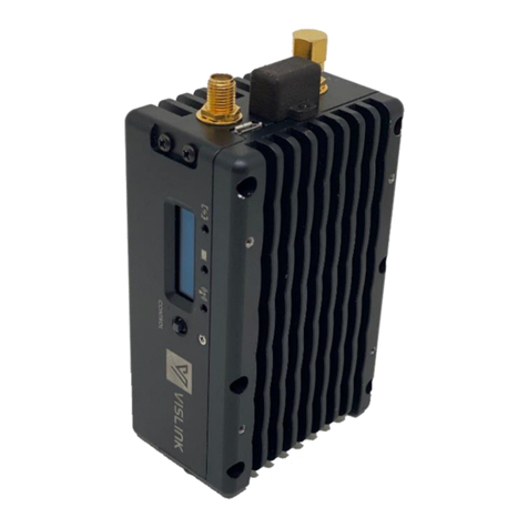
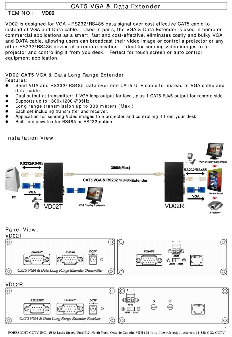
Vislink DragonFly Quick setup guide

Vislink, Waterside House, Earls Colne Business Park, Colchester, Essex, CO6 2NS, UK
Telephone: +44 (0)1442 431300 ●Facsimile: +44 (0) 1494 775356 ●Email: sales@vislink.com ●Website: www.vislink.com
Company Registered in England & Wales no. 10523708 ●VAT registration no. GB 260 012 169
Registered Office: Waterside House, Earls Colne Business Park, Colchester, Essex, CO6 2NS, UK
DragonFly
Transmitter
Installation and Integration Guide

Issue No: A Page: ii
Ref: DragonFly Installation Guide Copyright © 2020 IMT and Vislink are Vislink Technologies Inc. companies
Document Disclaimer
The information contained in this manual remains the property of Vislink and may not be
used, disclosed or reproduced in any other form whatsoever without the prior written
permission of Vislink.
Vislink reserves the right to alter the equipment and specification appertaining to the
equipment described in this manual without notification.
This document is supplied on the express terms that it is to be treated as confidential and
that it may not be copied, used or disclosed to others for any purpose except as authorized
by Vislink.
Trademark Information
Add any additional Trademark content from external companies from their websites
trademark pages etc.
Conventions
NOTE: Notes show to convey additional information.
CAUTION: Cautions show where potential equipment damage could occur.
WARNING: Warnings show where there is potential for personal danger or risk of
death. Read all warnings and understand them before carrying out work
on any equipment. This includes peripherals and any related equipment
in use. The danger is real and not reading and understanding the
warning could lead to injury, harm or potential death.
Service/Support Contacts:
Register for support:
Worldwide: https://support.imt-solutions.com
Call for support:
Worldwide: +44 1442 431410
USA: +1 978 330 9292
When contacting Technical Support, please include the model and serial number of the unit
(located on a label on the bottom of each unit) and the approximate date of purchase.

Issue No: A Page: iii
Ref: DragonFly Installation Guide Copyright © 2020 IMT and Vislink are Vislink Technologies Inc. companies
Document History
Version
Date
Modification
Author
1
09/08/2019
First draft
SMV

Issue No: A Page: iv
Ref: DragonFly Installation Guide Copyright © 2020 IMT and Vislink are Vislink Technologies Inc. companies
Table of Contents
1. General Information..............................................................................................5
1.1. General Safety Information ..................................................................................................5
1.2. Disposal Instructions...............................................................................................................5
1.3. Environmental .........................................................................................................................5
1.4. Health & Safety .......................................................................................................................6
1.5. Maximum RF Power Density Limits.....................................................................................7
2. Introduction ...........................................................................................................8
2.1. DragonFly Description............................................................................................................8
2.2. About This Guide.....................................................................................................................8
3. Product Descriptions and Kits.............................................................................9
3.1. Chassis Model ..........................................................................................................................9
3.2. Chassis Model Installation and Integration Overview ......................................................9
3.3. Outline Drawing ......................................................................................................................9
3.4. Connectors .............................................................................................................................10
3.4.1. Power and Serial Connector............................................................................................11
3.5. Camera Power and Control (SDI Only) .............................................................................11
3.6. Physical Installation..............................................................................................................12
3.7. OEM Board Model Kits..........................................................................................................13
3.7.1. Board Outlines ................................................................................................................. 15
3.7.2. Physical Installation OEM DragonFly Board Model Kit................................................. 18
Table of Figures
Figure 3-1: OEM DragonFly Chassis Model Outline Drawing ................................................... 10
Figure 3-2: Connectors ...................................................................................................................10
Figure 3-3: OEM DF Chase Installation ........................................................................................12
Figure 3-4 - Supplied Battery .........................................................................................................13
Figure 3-5 –Antenna........................................................................................................................ 13
Figure 3-6: Encoder Board Top View...........................................................................................16
Figure 3-7: Encoder Board Bottom View ....................................................................................16
Figure 3-8: RF Board Top View ..................................................................................................... 16
Figure 3-9: RF Board Bottom View - Pink Denotes RF Isolation ............................................17
Figure 3-10: Board Placement Cavity.......................................................................................... 17
Table of Tables
Table 1-1 Minimum Safe Distance Overview Table............................................................... 6

Guide DF Integration
Issue No: A Page: 5
Ref: DragonFly Installation Guide Copyright © 2020 IMT and Vislink are Vislink Technologies Inc. companies
1. General Information
1.1. General Safety Information
To ensure awareness of potential hazards, all personnel concerned with the operation or
maintenance of the equipment must study the information that follows, together with local
site regulations.
WARNING: RF Power Hazard: High levels of RF power are present in the unit.
Exposure to RF or microwave power can cause burns and may be
harmful to health. Switch off supplies before removing covers or
disconnecting any RF cables, and before inspecting damaged cables or
antennas.
WARNING: Avoid standing in front of high gain antennas (such as a dish) and never
look into the open end of a waveguide or cable where RF power may
be present.
CAUTION: We strongly recommended that you return any equipment requiring RF
servicing to Vislink.
WARNING- GaAs / BeO Hazard: Certain components inside the equipment contain
Gallium Arsenide and Beryllium Oxide that are toxic substances. Whilst
safe to handle under normal circumstances, individual components
must not be cut, broken apart, incinerated or chemically processed. In
the case of Beryllium Oxide, a white ceramic material, the principal
hazard is from the dust or fumes, which are carcinogenic if ingested,
inhaled or entering damaged skin.
Please consult your local authority before disposing of these components.
CAUTION: Tantalum Capacitors: When subjected to reverse or excess forward
voltage, ripple current or temperature these components may rupture
and could potentially cause personal injury.
CAUTION: This system contains MOS devices. Electro-Static Discharge (ESD)
precautions should be employed to prevent accidental damage.
1.2. Disposal Instructions
WARNING: DO NOT incinerate batteries. Exposing batteries to naked flames or
extreme heat sources can cause them to rupture or explode.
DO NOT dispose of any of the supplied equipment as household waste. The supplied
equipment is not biodegradable in landfill sites. For safe disposal of the supplied equipment,
take it to your local (council/authority) environmental waste site. For details, contact your
local authority/recycling center.
NOTE: In Europe dispose of all equipment in accordance with the European
Environmental directive.
1.3. Environmental
CAUTION: The unit is IPxx rated and must be protected from dripping or splashing
water/fluids. When used outdoors, protect the unit using a rain cover.

Guide DF Integration
Issue No: A Page: 6
Ref: DragonFly Installation Guide Copyright © 2020 IMT and Vislink are Vislink Technologies Inc. companies
1.4. Health & Safety
Exposure to Non-Ionizing (RF) Radiation/Safe Working Distances
The safe working distance from a transmitting antenna may be calculated from the
relationship:
D =
in which D = safe working distance (meters)
PT = transmitter or combiner power output (watts)
GR = antenna gain ratio = anti log (gain dBi ÷10)
w = Maximum allowed power density (watts/square meter)
The RF power density value is determined by reference to safety guidelines for exposure
of the human body to non-ionizing radiation. It is important to note that the guidelines
adopted differ throughout the world and are from time-to-time re-issued with revised
guidelines. For Vislink use, when calculating minimum safe working distances, apply a
maximum power density limit (w) of 1w/m². Appendix A refers.
WARNING: Any transmitting equipment, radiating power at frequencies of 100 kHz
and higher, has the potential to produce thermal and athermal effects
upon the human body.
To be safe:
a. Operators should not stand or walk in front of any antenna, nor should they
allow anyone else to do so.
b. Operators should not operate any RF transmitter or power amplifier with any of
its covers removed, nor should they allow anyone else to do so.
Worked examples:
Table 1-1 Minimum Safe Distance Overview Table
Antenna
Transmitter Power
Type
Gain (dBi)
Gain Ratio
2W
4W
10W
30W
OMNI
4
2.5
1
1
1.5
2.5
HELIX
20
100
4
5.6
9
15.5
PARABOLIC
DISH
35
3,162
22.5
32
50
87
MINIMUM SAFE DISTANCE (METERS)
PT. GR
4.w

Guide DF Integration
Issue No: A Page: 7
Ref: DragonFly Installation Guide Copyright © 2020 IMT and Vislink are Vislink Technologies Inc. companies
1.5. Maximum RF Power Density Limits
The RF Radiation Power Density limit figure recommended by Vislink is based upon
guideline levels published in:
a. IEEE standard C95.1 1999 - IEEE Standard for Safety Levels with respect to
Human Exposure to Radio Frequency Electromagnetic Fields, 3 kHz to 300 GHz.
b. Guidelines for Limiting Exposure to Time-varying Electric, Magnetic &
Electromagnetic Fields (up to 300 GHz) published in 1998 by the Secretariat of
the International Commission on Non-Ionizing Radiation Protection (ICNIRP).
Both documents define guideline RF power density limits for "Controlled" and
"Uncontrolled" environments. An uncontrolled environment is defined as one in which the
person subjected to the RF radiation may be unaware of and has no control over the
radiation energy received. The uncontrolled environment conditions can arise, even in the
best-regulated operations and for this reason, the limits defined for the uncontrolled
environment have been assumed for the Vislink recommended limit.
Documents a) and b) also show the RF power density guidelines to be frequency-
dependent. Different power density/frequency characteristics are presented in the two
documents. To avoid complexity and to avoid areas of uncertainty, Vislink recommends
the use of a single power density limit across the frequency range of 100 kHz to 300 GHz.
The 1w/m² power density limit we recommend satisfies the most stringent of the guidelines
published to date.
NOTE: The IICNIRP document is freely available for download from the internet at
www.icnirp.de/emfgdl (PDF file) the IEEE standard is available on loan from
Essex County Library on payment of a search fee.

Guide DF Integration
Issue No: A Page: 8
Ref: DragonFly Installation Guide Copyright © 2020 IMT and Vislink are Vislink Technologies Inc. companies
2. Introduction
2.1. DragonFly Description
The DragonFly transmitter is a miniature wireless video transmission system designed to
capture real-time, high-quality video from Point of View Cameras, UAV/UGV/Body
Cams/Concealments and static sports cameras for display on fixed or mobile applications.
The transmitter features HD/SD-SDI or optional HDMI inputs with COFDM transmission in a
small, lightweight chassis. The IMTDragonFly delivers up to 50mW of power in a package
weighing less than 1.2 grams/34 grams, providing long-range, reliable HD video
transmission. Perfect for the most demanding portable and drone-based applications.
The IMTDragonFly is a compelling choice when broadcast quality, exceptional range, and
reliability are required. IMT’s COFDM technology ensures the transmission of uninterrupted,
live TV pictures over long ranges, despite the effects of foliage, challenging terrain,
buildings, and other common non-line-of-sight limitations. This gives it a significant
advantage over uncompressed solutions.
An additional benefit of the IMTDragonFly compared to alternative solutions is the ability
to operate at latency levels as low as 70ms, making it well-suited for remote control
applications.
The DragonFly was designed with a compact size and weight form factor and minimized
power requirements, making it ideal for drone use. IMTDragonFly has an HD-SDI input for
a high-quality camera interface. IMT has also developed a new antenna design customized
specifically for use with micro drones.
The DragonFly may be configured or remotely controlled by the built-in Wi-Fi web server.
An Android or iOS device will see the IMTDragonFly and automatically open the control
browser. Optionally, a 900MHz transceiver enabling processing of in-flight commands
including camera control or gimbal manipulation.
2.2. About This Guide
This guide covers integration and installation of both OEM versions of the DragonFly:
1) Chassis Model –the chassis model is a fully packaged version with simple
integration that includes heatsinking methods.
2) Board Model –This OEM package includes the two mainboards and connectors –
the manufacturer using this version is expected to meet the installation
requirements as set out by the guide.
Throughout this Guide, the product is referred to as the ‘IMTDragonFly”, “IMTDF” or
simply “DF”.
The contents of this manual are as follows:

Guide DF Integration
Issue No: A Page: 9
Ref: DragonFly Installation Guide Copyright © 2020 IMT and Vislink are Vislink Technologies Inc. companies
3. Product Descriptions and Kits
3.1. Chassis Model
The chassis model features a fully integrated chassis with user access to all connectors. It
also includes kits for operational testing.
Table 3-1: OEM DragonFly Chassis Kit
Item No
Component Part
Part Description
Qty
1
TBD
DragonFly Product - 2GHz/5GHz SDI/HDMI Version
1
2
713-E364-01A-R
Antenna, Miniature, WIFI/ZigBee/WLAN, Dual Band,
MMCX MALE
1
3
921-B424-01A-R
Cable, BNC Male to MMCX Plug, RG-316 Coax, 12 inch
1
4
922-B1269-01A-R
Cable, 8-P Power Conn to Bare Tinned Leads, 12",
Dragonfly
1
5
922-B1270-01A-R
Cable, 8-P Power Conn to 2-P Molex, 12", Dragonfly
1
6
922-B1264-01A-R
Cable, 7.4VDC Tenergy Battery to 2-P Molex, 6",
Dragonfly V3
2
7
922-B1265-01A-R
Cable, TLP-2000 7.4VDC Li-ion Charger with 2-P
Molex, 6", Dragonfly V3
1
8
922-B1133-01A-R
Cable,USB2.0 Micro Conn Cable, 0.5 Meter USB B
Micro Male USB A Male
1
9
922-B1253-01A-R
Cable, Encoder Bd to Camera, 20", Dragonfly V2
1
10
940-DF-01-R
Dragonfly Anti-static Foam Insert for S-12739 Box
1
11
863-D0029-000-
RE
ESD CONDUCT SHIP BOX 10-1/8 X 8-1/2 X 2-
1/2";ULine S-12739
1
12
TBD
2-56 screws for chassis mounting
8
13
TBD
Thermal pad for heatsink
3.2. Chassis Model Installation and Integration Overview
This chapter contains steps for installing the DragonFly in typical applications where it may
be used. Due to the small size and power consumption of the DragonFly, it may be used in
various applications.
Note: .stp files will be sent on request for reference.
3.3. Outline Drawing

Guide DF Integration
Issue No: A Page: 10
Ref: DragonFly Installation Guide Copyright © 2020 IMT and Vislink are Vislink Technologies Inc. companies
Figure 3-1: OEM DragonFly Chassis Model Outline Drawing
3.4. Connectors
Figure 3-2: Connectors
1
3
4
5
6
2

Guide DF Integration
Issue No: A Page: 11
Ref: DragonFly Installation Guide Copyright © 2020 IMT and Vislink are Vislink Technologies Inc. companies
Table 3-2 - IMTDragonFly Connectors - SDI Version
Reference
Description
Type on Unit
Mating
1
SDI Input
MMCX - Female
MMCX - Male
2
Wi-Fi Output
Embedded Antenna
n/a
3
RF/900MHz Output
MMCX - Female
MMCX - Male
4
Program
Micro USB
Micro USB
5
Power/Serial Port/Remote
Molex - 501568-0807
Molex 5013300-800
Pins - 501334-0100
6
Camera Control
JST_SM06B-SURS-TF-6PIN
JST_SUHR-06V-S-B
Pins - SSUH-003T-PO.15
3.4.1. Power and Serial Connector
The 8 pin Molex (Reference #5 above) contains both power and serial bus connections. The
connector is as follows:
•DF Part Number –Molex 501568-0807
•Mating Connector –Molex 501330-0800
Table 3-3 - IMTDragonFly Power and Serial Connectors
3.5. Camera Power and Control (SDI Only)
The 8 pin Molex (Reference above #5) contains both power and 3 serial bus connections.
The connector is as follows:
•DF Part Number –JST_SM06B-SURS-TF(LF)(SN)
•Mating Connector –JST_SHR-06V-S-B
Table 3-4 - IMTDragonFly Camera Control Pinout
PIN
Type
Description
1
Power
6.5-16VDC
2
GND
Ground
3
S-Bus
Serial - 0-3VDC
4
Serial - CC with HDMI
RS422/485 - minus (HDMI Version)
5
Serial - CC with HDMI
RS422/485 - plus (HDMI Version)
6
GND
Ground
7
Serial - Remote Control
RS232- RX In
8
Serial - Remote Control
RS232- TX In

Guide DF Integration
Issue No: A Page: 12
Ref: DragonFly Installation Guide Copyright © 2020 IMT and Vislink are Vislink Technologies Inc. companies
3.6. Physical Installation
The OEM DragonFly Chassis model uses the 4 2-56 threaded screw holes on the bottom of
the unit to fasten to the installation location that is conducive to thermal dissipation. A
thermal pad is supplied with the OEM DFC Kit to help in the thermal transfer from the device
to the installation location.
1) Define the installation location
a. Make sure clearances are good.
b. Make 2-56 through holes matching the outline drawing above or using the
.stp files as a reference.
2) Place the thermal pad to align the through-holes with pattern in the DragonFly.
3) Fasten DragonFly in place using 4 2-56 screws supplied in the kit, or chose to fit.
4) Make or purchase cables need to run DragonFly. The following cable is needed to
be made:
a. Power and RS 232 serial cable
b. SDI cable –A SDI to BNC cable is supplied in the kit –however, a custom
one may be bought or made depending on needs.
c. Camera control –A 20-inch cable is supplied with the mating connector of
the CC connector. The other end is bare tinned leads and may be used to
attach directly to the camera or interface connectors that go to the camera.
d. Antenna extension cable –purchased or made.
Figure 3-3: OEM DF Chase Installation

Guide DF Integration
Issue No: A Page: 13
Ref: DragonFly Installation Guide Copyright © 2020 IMT and Vislink are Vislink Technologies Inc. companies
Figure 3-4 - Supplied Battery
Figure 3-5 –Antenna
3.7. OEM Board Model Kits
There are currently 4 OEM DragonFly Board Kits depending on the frequency and video
input type.
DragonFly OEM 2GHz SDI
Line Item
Part Number
Description
QTY
1
902-M096-01C-R
DRAGONFLY MODULATOR 2.0-2.3GHz
1
2
902-M094-01D-R
GEO H.264 VIDEO ENCODER
1
3
922-B1256-01A-R
Cable, Encoder Bd to Fan, Dragonfly V2
1
4
M47-DTX-OEM
DragonFly OEM Installation Guide
1
5
713-E364-01A-R
Antenna, Miniature, WIFI/ZigBee/WLAN, Dual Band, MMCX MALE
1
6
922-B1269-01A-R
Cable, 8-P Power Conn to Bare Tinned Leads, 12", Dragonfly
1
7
922-B1264-01A-R
Cable, 7.4VDC Tenergy Battery to 2-P Molex, 6", Dragonfly V3
2
8
922-B1265-01A-R
Cable, TLP-2000 7.4VDC LI-Ion Charger with 2-P Molex, 6", Dragonfly V3
1
9
922-B1133-01A-R
Cable,USB2.0 Micro Conn Cable, 0.5 Meter USB B Micro Male USB A
Male
1
10
940-DF-01-R
Dragonfly Anti-static Foam Insert for S-12739 Box
1
11
863-D0029-000-RE
ESD CONDUCT SHIP BOX 10-1/8 X 8-1/2 X 2-1/2";ULine S-12739
1
12
922-B1270-01A-R
Cable, 8-P Power Conn to 2-P Molex, 12", Dragonfly
1
13
922-B1253-01A-R
Cable, Encoder Bd to Camera, 20", Dragonfly V2
1
14
922-B1257-01A-R
Cable, JST SUHR-06V-S w/ SSUH-003T-P0.15, 610mm long, 28awg
2
15
514-C4010-S06-R
CONN HOUSING 6POS 1.25MM;MOLEX 51021-0600
10
16
514-C4029-S08-R
Conn, Receptacle, Housing, 8 posn, 1.0mm, Molex Pico-Clasp
2
17
515-F0040-000-R
CONN, TERM FEMALE, TIN, 28-32AWG, MOLEX PICO-CLASP
12
18
816-AB1X2-03M-R
SCREW, PPHS M1 X 0.25 Thread, 3mm long, 304 SS
15
19
839-AE080-N31-R
PFHS 0-80x5/16 100D NYLOK PTCH;PER SPEC 895-S_18-8-000
10
DragonFly OEM 2GHz HDMI
Line Item
Part Number
Description
QTY
1
902-M096-01C-R
DRAGONFLY MODULATOR 2.0-2.3GHz
1

Guide DF Integration
Issue No: A Page: 14
Ref: DragonFly Installation Guide Copyright © 2020 IMT and Vislink are Vislink Technologies Inc. companies
2
902-M095-01B-R
HDMI H.264 VIDEO ENCODER
1
3
922-B1256-01A-R
Cable, Encoder Bd to Fan, Dragonfly V2
1
4
M47-DTX-OEM
DragonFly OEM Installation Guide
1
5
713-E364-01A-R
Antenna, Miniature, WIFI/ZigBee/WLAN, Dual Band, MMCX MALE
1
6
922-B1269-01A-R
Cable, 8-P Power Conn to Bare Tinned Leads, 12", Dragonfly
1
7
922-B1264-01A-R
Cable, 7.4VDC Tenergy Battery to 2-P Molex, 6", Dragonfly V3
2
8
922-B1265-01A-R
Cable, TLP-2000 7.4VDC LI-Ion Charger with 2-P Molex, 6", Dragonfly V3
1
9
922-B1133-01A-R
Cable,USB2.0 Micro Conn Cable, 0.5 Meter USB B Micro Male USB A
Male
1
10
940-DF-01-R
Dragonfly Anti-static Foam Insert for S-12739 Box
1
11
863-D0029-000-RE
ESD CONDUCT SHIP BOX 10-1/8 X 8-1/2 X 2-1/2";ULine S-12739
1
12
922-B1270-01A-R
Cable, 8-P Power Conn to 2-P Molex, 12", Dragonfly
1
13
922-B1253-01A-R
Cable, Encoder Bd to Camera, 20", Dragonfly V2
1
14
922-B1257-01A-R
Cable, JST SUHR-06V-S w/ SSUH-003T-P0.15, 610mm long, 28awg
2
15
514-C4010-S06-R
CONN HOUSING 6POS 1.25MM;MOLEX 51021-0600
10
16
514-C4029-S08-R
Conn, Receptacle, Housing, 8 posn, 1.0mm, Molex Pico-Clasp
2
17
515-F0040-000-R
CONN, TERM FEMALE, TIN, 28-32AWG, MOLEX PICO-CLASP
12
18
816-AB1X2-03M-R
SCREW, PPHS M1 X 0.25 Thread, 3mm long, 304 SS
15
19
839-AE080-N31-R
PFHS 0-80x5/16 100D NYLOK PTCH;PER SPEC 895-S_18-8-000
10
DragonFly OEM 5GHz SDI
Line Item
Part Number
Description
QTY
1
902-M097-01C-R
ASSEMBLY PCB DRAGONFLY 4.9-5.9GHz MODULATOR
1
2
902-M094-01D-R
GEO H.264 VIDEO ENCODER
1
3
922-B1256-01A-R
Cable, Encoder Bd to Fan, Dragonfly V2
1
4
M47-DTX-OEM
DragonFly OEM Installation Guide
1
5
713-E364-01A-R
Antenna, Miniature, WIFI/ZigBee/WLAN, Dual Band, MMCX MALE
1
6
922-B1269-01A-R
Cable, 8-P Power Conn to Bare Tinned Leads, 12", Dragonfly
1
7
922-B1264-01A-R
Cable, 7.4VDC Tenergy Battery to 2-P Molex, 6", Dragonfly V3
2
8
922-B1265-01A-R
Cable, TLP-2000 7.4VDC LI-Ion Charger with 2-P Molex, 6", Dragonfly V3
1
9
922-B1133-01A-R
Cable,USB2.0 Micro Conn Cable, 0.5 Meter USB B Micro Male USB A
Male
1
10
940-DF-01-R
Dragonfly Anti-static Foam Insert for S-12739 Box
1
11
863-D0029-000-RE
ESD CONDUCT SHIP BOX 10-1/8 X 8-1/2 X 2-1/2";ULine S-12739
1
12
922-B1270-01A-R
Cable, 8-P Power Conn to 2-P Molex, 12", Dragonfly
1
13
922-B1253-01A-R
Cable, Encoder Bd to Camera, 20", Dragonfly V2
1
14
922-B1257-01A-R
Cable, JST SUHR-06V-S w/ SSUH-003T-P0.15, 610mm long, 28awg
2
15
514-C4010-S06-R
CONN HOUSING 6POS 1.25MM;MOLEX 51021-0600
10
16
514-C4029-S08-R
Conn, Receptacle, Housing, 8 posn, 1.0mm, Molex Pico-Clasp
2
17
515-F0040-000-R
CONN, TERM FEMALE, TIN, 28-32AWG, MOLEX PICO-CLASP
12
18
816-AB1X2-03M-R
SCREW, PPHS M1 X 0.25 Thread, 3mm long, 304 SS
15
19
839-AE080-N31-R
PFHS 0-80x5/16 100D NYLOK PTCH;PER SPEC 895-S_18-8-000
10
DragonFly OEM 5GHz HDMI
Line Item
Part Number
Description
QTY

Guide DF Integration
Issue No: A Page: 15
Ref: DragonFly Installation Guide Copyright © 2020 IMT and Vislink are Vislink Technologies Inc. companies
1
902-M097-01C-R
ASSEMBLY PCB DRAGONFLY 4.9-5.9GHz MODULATOR
1
2
902-M095-01B-R
HDMI H.264 VIDEO ENCODER
1
3
922-B1256-01A-R
Cable, Encoder Bd to Fan, Dragonfly V2
1
4
M47-DTX-OEM
DragonFly OEM Installation Guide
1
5
713-E364-01A-R
Antenna, Miniature, WIFI/ZigBee/WLAN, Dual Band, MMCX MALE
1
6
922-B1269-01A-R
Cable, 8-P Power Conn to Bare Tinned Leads, 12", Dragonfly
1
7
922-B1264-01A-R
Cable, 7.4VDC Tenergy Battery to 2-P Molex, 6", Dragonfly V3
2
8
922-B1265-01A-R
Cable, TLP-2000 7.4VDC LI-Ion Charger with 2-P Molex, 6", Dragonfly V3
1
9
922-B1133-01A-R
Cable,USB2.0 Micro Conn Cable, 0.5 Meter USB B Micro Male USB A
Male
1
10
940-DF-01-R
Dragonfly Anti-static Foam Insert for S-12739 Box
1
11
863-D0029-000-RE
ESD CONDUCT SHIP BOX 10-1/8 X 8-1/2 X 2-1/2";ULine S-12739
1
12
922-B1270-01A-R
Cable, 8-P Power Conn to 2-P Molex, 12", Dragonfly
1
13
922-B1253-01A-R
Cable, Encoder Bd to Camera, 20", Dragonfly V2
1
14
922-B1257-01A-R
Cable, JST SUHR-06V-S w/ SSUH-003T-P0.15, 610mm long, 28awg
2
15
514-C4010-S06-R
CONN HOUSING 6POS 1.25MM;MOLEX 51021-0600
10
16
514-C4029-S08-R
Conn, Receptacle, Housing, 8 posn, 1.0mm, Molex Pico-Clasp
2
17
515-F0040-000-R
CONN, TERM FEMALE, TIN, 28-32AWG, MOLEX PICO-CLASP
12
18
816-AB1X2-03M-R
SCREW, PPHS M1 X 0.25 Thread, 3mm long, 304 SS
15
19
839-AE080-N31-R
PFHS 0-80x5/16 100D NYLOK PTCH;PER SPEC 895-S_18-8-000
10
3.7.1. Board Outlines

Guide DF Integration
Issue No: A Page: 16
Ref: DragonFly Installation Guide Copyright © 2020 IMT and Vislink are Vislink Technologies Inc. companies
Figure 3-6: Encoder Board Top View
Figure 3-7: Encoder Board Bottom View
Figure 3-8: RF Board Top View

Guide DF Integration
Issue No: A Page: 17
Ref: DragonFly Installation Guide Copyright © 2020 IMT and Vislink are Vislink Technologies Inc. companies
Figure 3-9: RF Board Bottom View - Pink Denotes RF Isolation
Figure 3-10: Board Placement Cavity

Guide DF Integration
Issue No: A Page: 18
Ref: DragonFly Installation Guide Copyright © 2020 IMT and Vislink are Vislink Technologies Inc. companies
3.7.2. Physical Installation OEM DragonFly Board Model Kit
The OEM DragonFly Board Kit differs from the chassis model tremendously. The chassis
model is modular and is recommended for most applications. The Board model should be
used only when the DragonFly needed to be embedded in the system because of space or
when there is no other choice. There are two main reasons for this:
1) The RF sections must be isolated from each other for the unit to work correctly.
2) The high density of the part placement and the size constraints of the boards do
not make it conducive to easy design implementation.
Installation and Design Instructions
NOTES: Refer to the .stp files for exact measurements.
1) Design installation locations
a. The boards are stacked upon one another using a specifically design ledge
and a board to board connector.
b. The DF cavity design should follow the .stp files with regards to the RF
isolation, RF Board screw placements, the ledge and screw placements for
the encoder board, and the cover.
c. Using CAD design tools –design the chassis or the cavity placement for the
DF according to the .stp files.
d. The Wi-Fi antenna must not be covered by metal if you are using this
method for configuration
2) Install the RF Board
a. Install the heatsink pad on Analog Devices IC as shown in the figure below.
b. Place the RF board in the cavity with the RF isolation on the bottom
c. Fasten to cavity using the 11 M1 screws provided in the kit.
3) Install the Encoder board.
a. Stack the encoder board on top of the RF board to align the board-to-board
connectors
b. Gently push the boards together so the edges push to the ledge and the
board-to-board connector fully engages.
c. The Encoder board is held in place by the lid.
4) Lid Placement
a. Gently place the lid on top, compressing the encoder board down.
b. Fasten the lid in place using the 8 0-80 screws provided.
5) Place the thermal pad to align the through-holes with pattern in the DragonFly.
6) Make or purchase cables need to run DragonFly. Cable that may need to be made:
a. Power and RS 232 serial cable

Guide DF Integration
Issue No: A Page: 19
Ref: DragonFly Installation Guide Copyright © 2020 IMT and Vislink are Vislink Technologies Inc. companies
b. SDI cable –A SDI to BNC cable is supplied in the kit –however, a custom
one may be bought or made depending on needs.
c. Camera control –A 20-inch cable is supplied with the mating connector of
the CC connector. The other end is bare tinned leads and may be used to
attach directly to the camera or interface connectors that go to the camera.
d. Antenna extension cable –purchased or made.

Guide DF Integration
Issue No: A Page: 20
Ref: DragonFly Installation Guide Copyright © 2020 IMT and Vislink are Vislink Technologies Inc. companies
Figure 3-11: DF Installation Diagram
Other manuals for DragonFly
1
Table of contents
Other Vislink Extender manuals
