Viso Systems LabRail User manual
VISO SYSTEMS LabRail
User Manual
Revision: 29 March 2021

2
Congratulations on purchasing your new Viso Systems LabRail. Before using this
product, please read the Safety Information.
This manual contains descriptions and troubleshooting necessary to install and
operate your new Viso Systems product. Please review this manual thoroughly to
ensure proper installation and operation.
For news, Q&A and support at Viso Systems, visit our website at
www.visosystems.com

3
Contents
Safety Information........................................................................................................4
Disposing of this Product ..............................................................................................4
Introduction..................................................................................................................4
Product Dimensions......................................................................................................5
Rail installation .............................................................................................................7
Distance calibration ......................................................................................................8
Specifications..............................................................................................................14
4
Safety Information
Warning! This product is not for household use.
Read this manual before installing and operating the LabRail, follow the safety
warnings listed below, and study all the cautions in the manual.
Preventing electric shocks
Make sure the power supply is always grounded.
Use a source of AC power that complies with the local building and electrical codes,
that has both overload and ground-fault protection.
If the controller or the power supply are in any way damaged, defective, wet, or
show signs of overheating, disconnect the power supply from the AC power and
contact Viso Service for assistance.
Do not install or use the device outdoors. Do not spray with or immerse in water or
any other liquid.
Do not remove any covers or attempt to repair the controller or the power supply.
Refer any service to Viso.
Disposing of this Product
Viso Systems products are supplied in compliance with Directive 2012/19/EU on
waste - electrical and electronic equipment (WEEE) together with the RoHS Directive
2011/65/EU with amendments 2015/863. Help preserve the environment! Ensure
that this product is recycled at the end of its lifetime. Your supplier can give details of
local arrangements for the disposal of Viso Systems products.
Introduction
About this document
These guidelines describe the installation process of the LabRail and distance
calibratio procedure.
About the LabRail
The LabRail is a revolutionary new automatic sensor positioning system, which
includes fully motorized sensor positioning include data over power elliminating all
cables.
© 2007 Viso Systems ApS, Denmark
All rights reserved. No part of this manual may be reproduced, in any form or by any means,
without permission in writing from Viso Systems ApS, Denmark. Information subject to change
without notice. Viso Systems ApS and all affiliated companies disclaim liability for any injury,
damage, direct or indirect loss, consequential or economic loss or any other loss occasioned by
the use of, inability to use or reliance on the information contained in this manual.

5
Product Dimensions
Coming soon

6
More package content and shipping coming soon

7
Rail installation
The rail consist of 8 pieces of rail sections each being 1.5m long. The rail are inter
connected using brackets on top and buttom.
To ensure stability the rail should be mounted as shown below.
Each second wire set is crossed show above in blue preventing the rail from swinging
from side to side.
Aligning rail (Coming soon)
Slide in LabRail (Coming soon)
Mount End-stop (Coming soon)
Connecting power (Coming soon)

8
Distance calibration
Before the rail can be used must the distance between the mounted sensor and the
LabRail be calibrated and stored in the memory of the LabRail.
To make the calibration please make sure you have installed Viso Light Inspector
version 6.05.2 or later.
Go to menu Setup->LabRail and the following dialog will appear
Please ensure that the laser is hitting the centre of the target plate on the injector by
adjusting the screws next to laser measurement device as shown below.
Also make sure that the “Setup laser target plate”is mounted on the LabSpion with
the front being at the center of rotation of the LabSpion.
The reason for the “Setup laser target plate” being extended outwards by 10cm is so
the software can easily ensure that the laser always hits the plate during the setup

9
process, otherwise would a significant error of at least 10cm be detected by the
software. The “Setup laser target plate” is only used during the setup and is not
needed again after the setup procedure is completed.
The sensor must be adjusted in height so that the laser is pointing completely
horizontal to centre of the “Setup laser target plate” as shown below.
Another laser leveller can be used to ensure the sensor laser is in horizontal level
such as the below shown Bosch laser included with the LabSpion.
Aligning the LabCross laser (Coming soon)
After the steps above have been completed please click “Next”.

10
The system will now ask you to move the sensor to the end-
stop. Just use your hand to gently push the sensor until it
touches the end-stop and click “Done”.
Please make sure there are not obstacles in the room as the sensor will now start
moving down the complete range of the rail.
The system will now measure the complete length of rail and ensuring it is hitting the
laser target plate at different positions.
If you get errors saying the laser target plate was not hit, please check you rail is
straight and that there is no direct strong light hitting the target plate. A sensor is
located inside the target plate ensuring the laser always hits the plate, this too
ensure that correct distance is always measured from the end of the rail.
If you have strong light hitting the plate from general lighting in your measurement
room, you can make a plate and place in such a way it blocks the light hitting the
laser target plate.
When the rail distance setup has completed will the system get ready to measure
the sensor laser distance in combination with the rail laser distance to be stored in
the finished calibration. The window below will ask you if you would like make a
manual pre-check that sensor laser is hitting the “Setup laser target plate”as shown

11
below.
If you click the large button on top of the rail image will you be able to move the
sensor manually using the window shown below.

12
While the LabRail is moving are you able to observe that the laser from the sensor is
hitting the centre of the “Setup laser target plate” at all position. If this is not the
case, please adjust the sensor hight and tilt until it does.
When finished close the window and click “Finished checking”, the system will now
start the last part of the calibration.
The LabRail calibration is now finished and have been stored in the flash memory of
the LabRail so no future calibration is necessary.
You can now click finished.
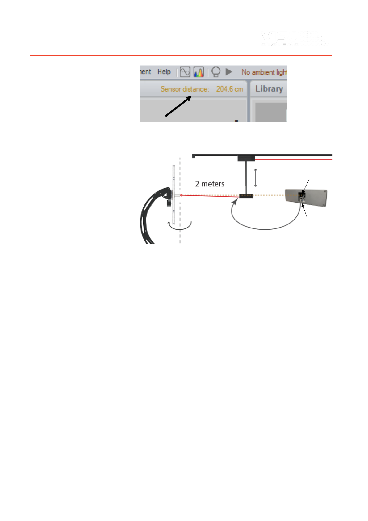
From this point on when ever you want to set a new measurement distance just click
on the distance label in Viso Light Inspector software as shown below.
13
Finally, you should set the sensor distance to 2 meters and re-adjust the sensor
height, so the spectrometer sensor is in the vertical centre of the goniometer as
shown below.
The laser module in the sensor is a bit offset in position in comparison with the
actual spectrometer sensor position. During factory sensor calibration are all
spectrometer sensor aligned to the laser beam at a 2 meter distance. This will give
some sensor positioning errors when measuring above or below 2m distances in
comparison with the laser point, but these error are of low factor and can therefore
without any problems be accepted.
Spectrometer sensor
Laser distance module

14
Specifications
Coming soon
Other manuals for LabRail
1
Table of contents
Other Viso Systems Laboratory Equipment manuals


Popular Laboratory Equipment manuals by other brands


Matrix
Matrix WellMate user manual

Parr Instrument
Parr Instrument 4703 Operating instructions manual

ibidi
ibidi Heating System instructions

Symmetricom
Symmetricom 5071A Operating and programming manual

Radiometer Analytical
Radiometer Analytical TitraLab TIM840 user guide

MELAG
MELAG Vacuklav 24-B/L user manual


