Viso Systems LabAnalyzer User manual

Preliminary User Manual
VISO SYSTEMS
LabAnalyzer
Preliminary User Manual
Revision: 23-05-2023

Preliminary User Manual
2
Congratulations on purchasing your new Viso Systems LabAnalyzer. Before using this
product, please read the Safety Information.
This manual contains descriptions and troubleshooting necessary to install and
operate your new Viso Systems product. Please review this manual thoroughly to
ensure proper installation and operation.
For news, Q&A and support at Viso Systems, visit our website at
www.visosystems.com

Preliminary User Manual
3
Contents
Safety Information ........................................................................................................4
Disposing of this Product ..............................................................................................4
Introduction ..................................................................................................................4
Contents........................................................................................................................5
Shipping dimensions and weight ..................................................................................5
LabAnalyzer Introduction..............................................................................................6
Fitting LabAnalyzer into your light lab ..........................................................................6
Remote sense function .................................................................................................6
Sensor Synchronization for flashing lights ....................................................................7
Product specifications...................................................................................................8

Preliminary User Manual
4
Safety Information
Warning! This product is not for household use.
Read this manual before installing and operating LabAnalyzer, follow the safety
warnings listed below, and study all the cautions in the manual.
Preventing electric shocks
Make sure the power supply is always grounded.
Use a source of AC power that complies with the local building and electrical codes,
that has both overload and ground-fault protection.
If the controller or the power supply are in any way damaged, defective, wet, or
show signs of overheating, disconnect the power supply from the AC power and
contact Viso Service for assistance.
Do not install or use the device outdoors. Do not spray with or immerse in water or
any other liquid.
Do not remove any covers or attempt to repair the controller or the power supply.
Refer any service to Viso.
Disposing of this Product
Viso Systems products are supplied in compliance with Directive 2012/19/EU on
waste - electrical and electronic equipment (WEEE) together with the RoHS Directive
2011/65/EU with amendments 2015/863. Help preserve the environment! Ensure
that this product is recycled at the end of its lifetime. Your supplier can give details of
local arrangements for the disposal of Viso Systems products.
Introduction
About this document
These guidelines describe the installation and use of Viso LabAnalyzer.
About the LabAnalyzer
The LabAnalyzer is a Power Analyzer (2-270 V AC/DC max 16.5Amp).
© 2023 Viso Systems ApS, Denmark
All rights reserved. No part of this manual may be reproduced, in any form or by any means,
without permission in writing from Viso Systems ApS, Denmark. Information subject to change
without notice. Viso Systems ApS and all affiliated companies disclaim liability for any injury,
damage, direct or indirect loss, consequential or economic loss or any other loss occasioned by
the use of, inability to use or reliance on the information contained in this manual.

Preliminary User Manual
5
Contents
LabAnalyzer
2 m Power Cable (standard Schuko)
2 m Power Cable (US)
2 m Power Cable (UK)
USB Cable, 3 m
Light Source Power Cable (DUT power)
Remote Sensing Cable (grey)
Calibration Certificate
Ethernet cable for sesnor sync
Input Power Supply Cable
Shipping dimensions and weight
Shipping Packages
Shipping
Dimensions
Shipping
Volume
Weight
1. LabAnalyzer + cables 400x300x150 mm 0,0324 m33,0 kg
Total shipping weight: 3,0 kg.

Preliminary User Manual
6
Total shipping CBM: 0,0324 m3
The shipment is done in a total of 1 package.
LabAnalyzer Introduction
The LabAnalyzer is n AC / DC Power Analyzer (10A peak 800VDC peak or 280VAC).
LabAnalyzer is dedicated to working with all Viso Light Measurement Systems
(LightSpion, LabAnalyzer, LabSpion) and Viso Light Inspector software, but may also
work as a stand-alone unit.
To comply with light measurement standards (such as IES LM-79 and CIE S 025), your
devices must be tested under rated conditions with specific tolerances.
Every Viso light measurement system includes a basic built-in power analyzer. The
LabAnalyzer bypasses the built-in analyzer and adds more accuracy and specific
features that makes the test circuit and analyzer uncertainties comply IES LM-79 and
CIE S 025 requirements.
An external integrated power analyzer provides several advantages:
Because of the optional remote sensing option, you may secure stable feed
right on the light source/driver terminals.
The combined instrument is compact and will fit right next to your Viso
gonio without the need of a rack
LabAnalyzer just needs one communication cable to your PC with the Light
Inspector software.
Real-time readout of both on Voltage and Current curves.
Optional remote voltage sensing for optimal accuracy.
Sensor Synchronization for flashing lights
Fitting LabAnalyzer into your light lab
Because of the remote sensing option, it is an advantage to keep the LabAnalyzer
close to the DUT (device under test) and not in a rack. Just place the rugged
LabAnalyzer case close to your goniometer.
Remote sense function
Requirements in standards:
Some light measurement standards require a remote sensing function applied for
correct voltage measurements:
LM 79-19: “Test Circuit Requirements. To Avoid effects of voltage drops in cables or
sockets, voltage measurements shall use separate sense leads connected at the
point where the supply leads attach to the DUT (…)”
CIE S 025/E2015: Electrical Test Conditions: “(…) The test voltage shall be measured
at the supply terminals of the DUT, not at the output terminals of power supply, to
avoid errors due to voltage drop by the cables and connectors.”

Preliminary User Manual
7
Connecting the remote sense cable to the DUT
Use the cage clamp terminal blocks of the remote sense cable.
Tip: It is not dangerous to accidentally swap source and external voltage sense
polarity though the voltage curve will be inverted on the display.
Sensor Synchronization for flashing lights
The LabAnalyzer can synchronise power pulses with the LabSensor this makes it
possible to make accurate measurement of lamp which are continuously flashing.
More information to come............

Preliminary User Manual
8
Product specifications
Physical dimensions
Dimensions (L x W x H)
Weight
270 x 220 x 105 mm
2 kg
Power input specifications
Maximum Input voltage
Maximum input Current
AC: 270 VAC 50/60 Hz
DC: 380V
14A peak and 7A RMS
Prerequisites for power analyzer accuracy
Device Under Test Voltage
Device Under Test Current
Ambient Temperature
5 – 270 VAC /5 – 380 V DC
<14A peak and 1mA – 7A RMS
25 ± 1.2 C
Power Analyzer Specifications
Basic Power Accuracy (50/60 Hz)
Analyzer Frequency Range
Calibration uncertainty, voltmeter/ammeter
Calibration uncertainty, power meter
Voltage Accuracy
Current Accuracy
Voltage AC peak ranges (Crest factor = 3 dB)
Current AC peak ranges (Crest factor = 3 dB)
Voltage range
Power range AC
Power range DC
Measurement Bandwidth
Sample rate
Output curve sample rate
Measurement Parameters
Current sense series resistance
Voltage internal sense parallel impedance
Voltage external sense parallel impedance
Remote sensing function
0.5%
up to 100 kHz
<0,2%
<0,5%
0.2% of reading + 0.2% of range
0.3% of reading + 0.3% of range
6V / 12V / 25V / 51V / 103V / 206V / 413V / 826V
3mA / 7mA / 15mA / 30mA / 60mA / 128mA / 257mA / 515mA / 1A / 2A / 4.1A / 8.2A
/ 16.5A
2-270V AC/DC
0.05W to 1700W @ 240VAC / 850W @ 120 VAC
0.05W to 1700W @ 240VDC / 850W @ 120 VDC / 170W @ 24VDC / 85W @ 12VDC
Higher power values available open request (with cost of higher minimum power)
200 kHz
2 MS/s
125 KS/s
Voltage, current, active power, apparent power, power factor, displacement factor.
0.1 Ω
3 MΩ
3 MΩ
Included (Max. test circuit resistance <0.5 Ω, Max. test circuit capacitance <1.5 nF)
Software
Connection
USB connection to Viso Light Inspector software

Preliminary User Manual
9
At Viso Systems we design, develop and manufacture OEM and customer-specific
light measurement solutions. Our mission is to support customers with powerful, yet
easy-to-use control and test solutions. Products are developed, manufactured, test
and calibrated in Copenhagen, Denmark.
Table of contents
Other Viso Systems Laboratory Equipment manuals
Popular Laboratory Equipment manuals by other brands

FARMALABOR
FARMALABOR TOP BLISTER Use and maintenance manual
Thermo Scientific
Thermo Scientific Barnstead EASYpure RODI 1332 Series Operation manual and parts list

Nikon
Nikon TIRF2 instructions

Koehler
Koehler K44100 Operation and instruction manual

Thermo Scientific
Thermo Scientific 180 Series Operating and maintenance manual

USA Scientific
USA Scientific ErgoOne user manual
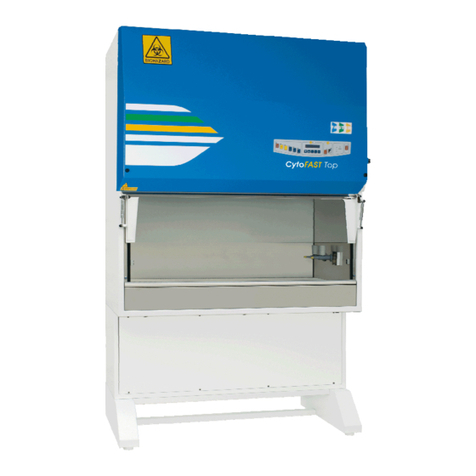
D
D FASTER CytoFAST Top Operating and maintenance manual

SATA
SATA 03081 user manual

Luxtron
Luxtron 710 user manual

Promega
Promega Maxwell 16 MDx Technical manual
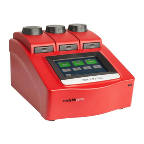
Endress+Hauser
Endress+Hauser Analytik Jena Biometra TRIO Series operating manual
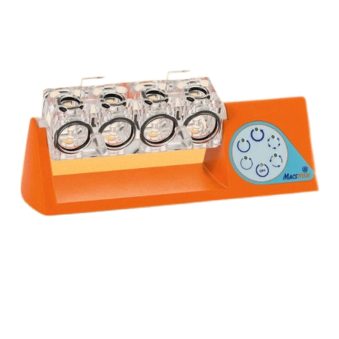
Miltenyi Biotec
Miltenyi Biotec MACSmix Tube Rotator user manual
