ABS ABT-FRP-04 User manual

OWNER’S GUIDE
Flammable Material Storage Refrigerator and
Freezer with D-100 Alarm System & Microprocessor
Temp Control V5.2
Table of Contents
RECEIVING AND SHIPPING DAMAGE HANDLING .............................................2
SAFETY ...........................................................................................................3
RELEASE OF LIABILITY .....................................................................................3
ELECTRICAL INFORMATION ............................................................................4
INSTALLATION................................................................................................5
OPERATION....................................................................................................7
Quick Troubleshooting Guide .......................................................................16
Maintenance and Cleaning ...........................................................................19
Hydrocarbon Service Notes ..........................................................................21
Factory Warranty Policy ...............................................................................22
PN: 21638
Rev. 6-27-2016

P a g e | 2
RECEIVING AND SHIPPING DAMAGE HANDLING
Each refrigerator or freezer is carefully inspected to meet our high standard quality
assurance policy, before it ships to you. Unfortunately, shipping damage can happen
during transportation to you. There are two general types of shipping damage. The
first is visible damage. This type of damage includes visible loss, damage, shortage or
any external evidence of loss or damage that is visible at time of delivery. This type of
damage must be noted in detail on your delivery receipt. Make sure the driver signs
and dates the delivery receipt, acknowledging the damages. We also recommend to
take many pictures to demonstrate and document the damaged area(s). This has to
happen at the time of delivery or it won’t happen at all. Keep a copy for your records
and send another to the carrier’s damage claims department along with a formal
request for an inspection report. Follow up with a phone call. Their contact information
can be found on the carrier’s web site.
The second type of shipping damage is concealed damage. This type of damage will
probably not be apparent at time of delivery and may not be discovered until
unpacking and inspecting the unit. Remember, time is of the essence here. You should
unpack and inspect the unit as soon as possible. Each day that passes reduces the
likelihood that the carrier will pay the claim. As soon as the concealed damage is
discovered, stop unpacking and retain all packing materials. Take many pictures to
demonstrate and document the concealed damage area(s). Contact the carrier by
phone to report the claim. Note the date and time and person you spoke with. Get a
claim number. Follow up with a written letter referencing the claim number and
including a formal request for an inspection. Again, consult the carrier’s website for
specific claim instructions and follow them precisely.
AS STATED ABOVE, THE CARRIER IS YOUR SOLE SOURCE FOR SATISFACTION OF
A DAMAGE CLAIM. UNDER NO CIRCUMSTANCES SHOULD THE MERCHANDISE BE
RETURNED TO THE MANUFACTURER. NO RETURNS WILL BE ACCEPTED WITHOUT
PRIOR AUTHORIZATION.

P a g e | 3
SAFETY
For your safety
DO NOT store any unsealed chemical material in this refrigerator or freezer.
Corrosive fumes from chemical material can linger inside of the chamber,
and cause serious damage to the refrigeration coils. Storing unsealed
chemical material in this equipment will void the factory product warranty.
DO NOT operate this equipment in the presence of explosive fumes. This
equipment is not rated to be a hazardous locations refrigerator or freezer.
Keep all flame sources or heat objects away from this refrigerator or freezer.
Disconnect power before servicing this refrigerator or freezer.
This is a flammable material storage refrigerator or freezer. All laboratory safety
rules must be followed during the operation of this refrigerator or freezer.
RELEASE OF LIABILITY
Before you start to use this refrigerator, please take a moment to:
Connect your remote alarm contacts system, or auto dialer, to the
refrigerator’s alarm system (if any).
If your refrigerator model does not have an alarm system, you can
install your 3rd party alarm into our refrigerator via the 3/8” access
porthole. Please see “Field Monitor Probe Installation” Section.
Develop an emergency backup plan, and designate a different
refrigerator or freezer to store the contents, if this refrigerator has an
unforeseen issue.
IF YOU PLAN TO STORE IRREPLACEABLE AND/OR HIGH VALUE PRODUCTS IN
THIS UNIT TAKE THE PROPER PRECAUTIONS NOW.

P a g e | 4
The manufacturer’s sole obligation under this warranty is limited to either repair or
replacement of parts, subject to the additional limitations below. This warranty
neither assumes, nor authorizes any person to assume obligations other than those
expressly covered by this warranty.
NO CONSEQUENTIAL DAMAGES. The manufacturer is not responsible for economic
loss, profit loss, or special indirect or consequential damages, including without
limitation, losses, or damages arising from contents spoilage claims whether or not
on account of refrigeration or mechanical failure.
ELECTRICAL INFORMATION
The supply circuit to this cabinet must
conform to NEC (National Electrical Code).
Consult the cabinet Serial-Data plate for
voltage, cycle, phase, and amp
requirements before making connection.
SUPPLY VOLTAGE SHOULD NOT VARY
MORE THAN 5% FROM SERIAL PLATE
RATINGS.
DO NOT connect this equipment to a GFI
(Ground Fault Interrupt) circuit.
Do not use an extension cord or any multi-
outlet strip or plug. Using such devices can lead to insufficient power, and lead
to component failure, such as the compressor or starting components.
If the power cord is damaged, it should be replaced immediately by an
authorized service technician.
Be sure your unit is properly grounded. Use the 3-prong plug provided into a 3-prong
grounded outlet. Unless the above grounding method is followed, you are not
protected against severe or lethal shock in the event of a short circuit of an electrical
component or wiring of the unit.

P a g e | 5
INSTALLATION
Please take a moment to follow the steps below, before using this equipment.
1. Find a suitable location to install this refrigerator (or freezer)
2. Level this refrigerator (or freezer)
3. Set up the shelves inside (if applicable)
4. Install the optional monitor probe for field installation
5. Ready to use
1. SUITABLE LOCATION
Ambient Temperature –Unlike a household refrigerator, this equipment is designed
for scientific / medical application. Many components are heavy duty and extra
sized, in order to meet the ultimate temperature performance. Therefore, the
sounds generated from its operation may not be accepted by everyone in the room.
Please take the operation sound factor into consideration, and locate this refrigerator
accordingly.
Please ensure the ambient temperature is climate-controlled, between 65°F to 85°F,
in order to achieve the ultimate temperature performance.
Clearance Space –We require 2 to 3 inches of clearance space around the refrigerator.
So it would be easier to remove the refrigerator for annual maintenance, or service.

P a g e | 6
2. LEVELING
Once this refrigerator or freezer is at its final location, please level your refrigerator,
because it is critical to equipment operation. Here are a few benefits to a good leveled
refrigerator (or freezer):
1. Moving mechanical parts, such as fan or compressor, would have less chances
to fail, since it is in the designed upright position.
2. Reduce noise.
3. Door(s) would close properly.
4. Condensate water would flow out the refrigerator properly.
To level this equipment, set a leveler in each corner on the top. If the equipment is not
level, adjust either the leveling legs or casters.
We recommend to slightly tilt the refrigerator (or freezer) toward to the back,
about 5 degrees. So the non-self-closing door can be shut properly, and condensate
water would flow out easier.
3. (OPTIONAL) MONITOR PROBE FOR FIELD INSTALLATION
Each refrigerator or freezer is equipped with a 3/8” probe access port hole for your
independent probe installation. The port hole is generally located in the back of your
refrigerator (or freezer). Simply remove the white caps, run your probe through, and
seal the hole with electrical putty to prevent air from getting into the chamber.
DO NOT run your probe through the door gasket, as it may cause serious
condensation or a frozen evaporator issue. The port hole is specifically designed to
allow you to install the monitor probe.
4. READY TO USE
Once you ensure the electrical service is adequate and Steps 1 to 3 are followed, you
are ready to use this refrigerator (or freezer). Simply plug in the power cord into the
wall outlet.
This refrigerator (or freezer) is factory set to run at its ultimate temperature
performance. There should not be a need to adjust the temp settings. If you feel the
temp settings must be adjusted, please refer to “TEMPERATURE ADJUSTMENT” section
in this manual for more details.

P a g e | 7
OPERATION
INTRODUCTION
Upon receiving the refrigerator or freezer, please take a moment to activate the
battery to D-100 alarm system. The battery supports D-100’s alarm operation during
a power failure event. This is an important step. See the following information on the
battery backup alarm function.
D-100 temp display and alarm system is specifically designed to display the
refrigerator’s interior sample temperature, and give out alarms if an error occurs.
FEATURES
Sample temperature display
Visual Alarm
Decimal temperature readout
Audible Alarm
Battery backup for power failure
Remote Alarm
One point HI and LO temp history
High temp alarm
Temperature calibration (offset)
Low temp alarm
°C/°F readout switch
Power failure alarm
Bi-color background readout
Sensor error alarm

P a g e | 8
MAIN SCREEN
During the normal operation, the display shows the interior temperature. The
background color will be green.
During an alarm condition, the display toggles between the current interior
temperature, and error code. The background color would be flashing red.
ALARM CODE
CODE
DESCRIPTION
HA
High Temperature Alarm
LA
Low Temperature Alarm
SA
Temperature Sensor Failure Alarm
dA
Door Ajar Alarm
PF
Main Power Failure Alarm
BATTERY BACKUP & POWER FAILURE ALARM
The D-100 battery backup system uses 4 each AA rechargeable batteries. During the
power failure, the batteries will support the alarm system and the temperature display
for 8 hours. When the power resumes, the batteries will be automatically recharged.
During a power failure event, the visual display will turn into flashing red background
with “PF” (power failure) message. Audible alarm & remote alarm contact would be
activated to alert users. The D-100 will still display and monitor the refrigerator
temperature during a power failure event until the battery power is depleted.
Once the power resumes, the display will still be flashing red, and showing “PF”
message, even if the refrigerator’s temperature is normal. It is a feature to alert
users that a power failure event has occurred. Users should check the temperature
history on the display. To clear the “PF” message, press any button.

P a g e | 9
CHECK TEMPERATURE HISTORY
Press [UP] button. The display will show the maximum temperature ever reached since
the last reset.
Press [DOWN] button. The display will show the minimum temperature ever reached
since the last reset.
Press [UP] and [DOWN] button together simultaneously for 4 seconds to clear out the
history. The maximum and minimum record will be erased, and record the next
maximum and minimum temp point.
MENU
Press [MENU] button to enter the user adjustable settings. Press [UP] or [DOWN] to
select which setting you would like to make an adjustment.
CODE
DESCRIPTION
FACTORY DEFAULT
ALU
High temp alarm point
10°C or 50°F (refrigerator)
0°C or °F (freezer)
ALL
Low temp alarm point
0°C or 32°F (refrigerator)
-30°C or °F (freezer)
Ad
Visual & audible alarm delay (minute)
0 (minute)
CF
Celsius & Fahrenheit unit change
°C or °F
dA
Door ajar alarm (minutes)
NO (disable)
Door alarm is for selected
models only.
rD
Remote alarm delay (minute)
20 (minute)
Snd
Mute duration (minute)
120 (minute)
OFF
Temp readout calibration / offset
Current readout

P a g e | 10
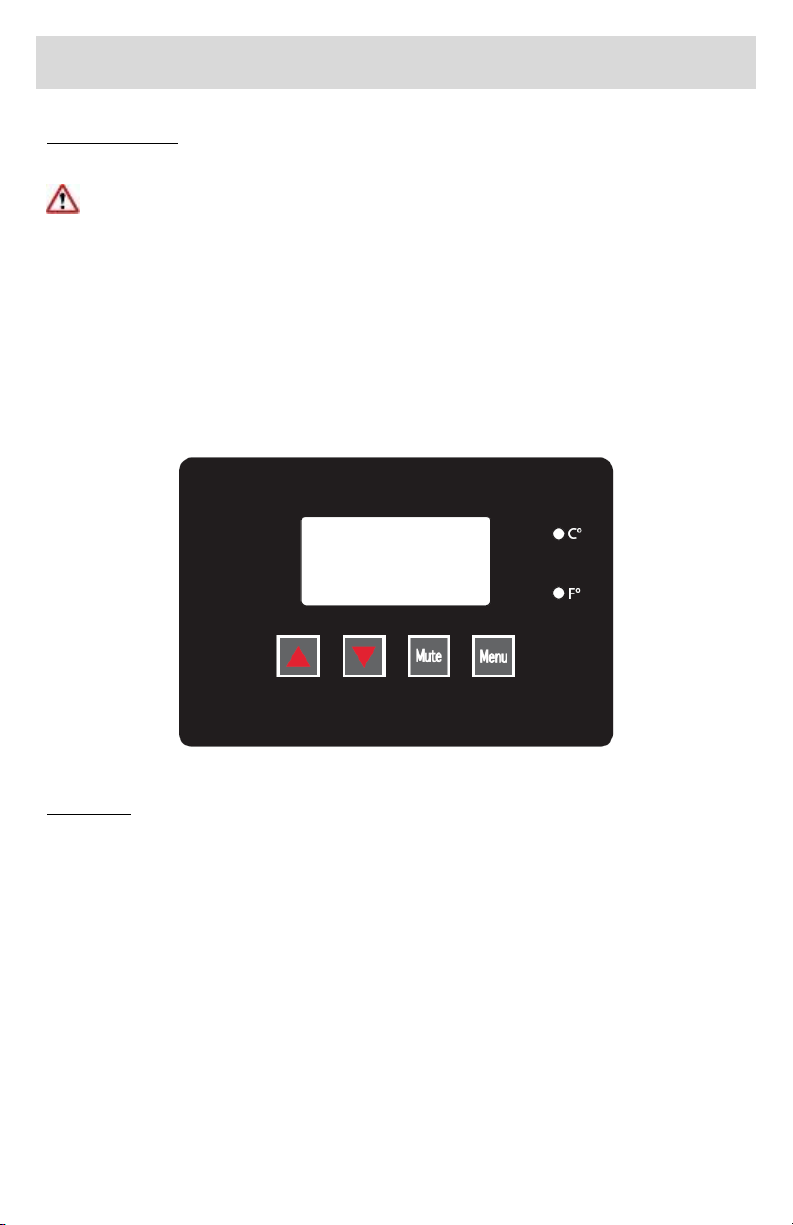
At each setting, press [UP] or [DOWN] to make a change. Then press [MENU] to
confirm the new change, and move to the next setting.
For example, to change the low temp alarm point: press [MENU] till the display
shows [ALL]. Press [UP] to change the factory setting 0C to 1C. Press [MENU] to
confirm the setting. And the display will show “Ad” next.
To return to the main display, either cycle through the entire menu from “ALU” to
“OFF”, or simply take no action for 30 seconds. The display will return to the
temperature display mode.
HIGH TEMP ALARM POINT (ALU)
Under this function, you are able to change the high temperature alarm point. Once
the refrigerator temperature reaches the set point, D-100 will display “HA” message,
and send out the audible alarm.
LOW TEMP ALARM POINT (ALL)
Under this function, you are able to change the low temperature alarm point. Once
the refrigerator temperature reaches the set point, D-100 will display “LA” message,
and send out the audible alarm.
VISUAL & AUDIBLE ALARM DELAY (Ad)
This function allows users to adjust the time delay between the occurrence of an error
and the visual & audible alarm’s activation. For example, if the setting is 1 (minute),
when the temp warms above the high temp alarm point, it would take 1 minute before
the visual and audible alarm are activated.
We recommend to keep the setting at 0 (minute).
CHANGE TEMPERATURE READOUT BETWEEN °C AND °F
Press [MENU] 4 times till “CF” displays. Press [UP] or [DOWN] to change between °C
and °F. The right side °C / °F indicator will toggle according to your selection. Press
[MENU] again to confirm your change.
DOOR AJAR ALARM (dA)
This feature is disable on most models (Setting: NO). Only selected models have the
door alarm switch installed, and feature unlocked. If your refrigerator model does not
have the door alarm switch installed, and dA setting is turned on to 0 to 5 (minutes),
the display will give out dA (door ajar) alarm even when the door(s) is closed.
If your refrigerator has the door alarm switch(s) installed, you can change the door ajar
alarm duration from 0 minute to 5 minutes. If one or more doors is opened out of
duration time period, the display will activate “dA” message. Once the door is closed,
the alarm will be turned off.

P a g e | 11
MUTE DURATION “RINGBACK” (Snd)
This feature can be considered as a “nudge” alarm. If a user mutes the audible alarm,
but an alarm condition persists, the audible alarm will ring back after 120 minutes later
(factory setting). This is to prevent a serious alarm condition to be ignored.
CALIBRATION / OFFSET (OFF)
Before making an OFFSET change, please note that this procedure should only be
carried out by a certified technician with a NIST traceable calibrated thermometer.
This feature allows a user to change the temperature reading with +/- 10 degree
differences.
For example, if a technician’s NIST traceable calibrated thermometer is reading 5C,
while D-100 reads 3C, make a +2C change in OFF setting.
REMOTE ALARM DELAY (rD)
It is a time delay after the visual and audible alarm being activated. It gives users some
time to correct an error, before sending the alarm to the remote monitor system.
For example, rD is set to be 20 (minutes). A user forgets to close the refrigerator’s
door, and the temperature warms up to 10C. The High Temp (HA) visual and audible
alarm will be activated. If the temperature continues to stay above High Temp, 20
minutes later the remote alarm will be activated.
Please note, Remote Alarm will be immediately activated during a power failure event.
It would be deactivated when the power resumes and the temperature returns to
normal.
REMOTE ALARM SYSTEM (SPST RELAY)
It is recommended to contact your facility manager, or a local technician to assist you
in connecting the remote alarm system.
D-100’s remote alarm system is wired to be gray and white leads. It is located at either
1) underneath of top sign canopy, or 2) behind the unit, next to the compressor.
During non-alarm state, the remote alarm system is at CLOSED position (NC). During
an alarm state, the system is at OPEN position.
Rating: 3 amps.

P a g e | 12
Temperature Controller System
Product Description
The digital microprocessor temperature controller is designed to provide temperature
control of refrigerators or freezers. The controller also provides a constant readout of
the sample temperature inside of the unit. A touch keypad allows the user to easily
select the display units, set point, and differential set point.
Please Note: The digital temperature controller has been factory
set and tested to allow your unit to operate at its desired
temperature cycle.
Adjusting the settings on the controller will alter these factory
settings. WE STRONGLY RECOMMEND YOU CONTACT THE
MANUFACTURER’S TECHNICAL SUPPORT DEPARTMENT BEFORE
MAKING ANY ADJUSTMENTS TO THIS CONTROLLER. TECH SUPPORT
PHONE NUMBER IS (800) 648 4041 Option 4

P a g e | 13
CHECK TEMPERATURE HISTORY
Press and release [UP] button. The display will show the maximum temperature ever
reached since the last reset.
Press and release [DOWN] button. The display will show the minimum temperature
ever reached since the last reset.
Press and hold [SET] for more than 3 seconds, while the maximum or minimum temp
is displayed. (rSt message will be displayed).
CHECK THE SET POINT
Press and release [SET] button. The display will show the current set point value.
Operation
During the normal operation, the refrigerator’s (or freezer’s) compressor would turn
on and off, in order to maintain the cold temperature in the storage chamber.
In this controller, the point where the compressor is cut off is called “SET POINT”.
The point where the compressor is turned on is calculated by adding the value of
“SET POINT” and “Hy” (temp differential).
For example, if you wish to maintain the operation temperature between 3°C and
7°C, you would set “SET” = 3°C, and “Hy” = 4°C.
“ALU” is the high temp alarm point, and “ALL” is the low temp alarm point. Both
alarm settings will alert users when the refrigerator’s (or freezer’s) temp is out of
range, via visual & audible alarm, and remote alarm contact.
“US” is the upper setting limit, and “LS” is the lower setting limit. Both limit settings
will prevent users accidentally adjust “SET”, “ALU”, or “ALL” outside the range.

P a g e | 14
CODE
DESCRIPTION
FACTORY SETTING
SET
Temp set point (compressor off point)
3°C or 38°F (refrigerator)
-24°C or -12°F (freezer)
Hy
Temp differential between compressor
start and off point
3°C or 5°F (NOT
RECOMMENDED TO
CHANGE)
ALL
Low temp alarm point
1°C or 34°F (refrigerator)
-28°C or -18°F (freezer)
ALU
High temp alarm point
10°C or 50°F (refrigerator)
-15°C or 5°F (freezer)
Lod
Screen display choice (air or sample probe)
P3
CF
Celsius & Fahrenheit unit change
O3
Sample (display) probe calibration / offset
0
OT
Air (control) probe calibration / offset
0
US
The maximum limit that SET or ALU could
reach
10°C or 50°F (refrigerator)
-10°C or 14°F (freezer)
LS
The minimum limit that SET or ALL could
reach
1°C or 34°F (refrigerator)
-30°C or -22°F (freezer)
Change the set point (compressor turn-off point)
Press and hold [SET] until °C or °F icon blinking. Press [UP] or [DOWN] to change the
setting value. Then, press [SET] once to confirm the new setting.
Change the other settings
Press and hold both [SET] and [DOWN] at the same time until “Hy” appears on the
display.
Press [UP] or [DOWN] to scroll different settings. Press [SET] to enter the setting.
Press [UP] or [DOWN] to change value. Press [SET] once to confirm the new setting.
The display will show the next setting.
At any setting, press and hold both [SET] and [UP] to exit out the setting mode, or
simply leave the display alone for 10 seconds.
Change the readout from °C to °F, or °F to °C
Press and hold the [LIGHT] icon button for 5 seconds. The controller will restart and
change the display scale from °C to °F, or °F to °C.

P a g e | 15
Advanced Settings –for service technician only
ATTENTION: This section is for service technicians or experienced users
only. Altering the following settings can result in malfunction or inaccurate
temperature readout.
Air and Sample Temperature Display
The controller has the capability to display either the air or sample temperature
readout. For the normal operation, the sample-simulated temperature (P3) is
displayed in order to provide users the content temperature. For the actual
operation, the air temperature (P1) is used to control the compressor’s cycle.
This is a useful tool for you to make a precise adjustment, or temperature validation
process.
“Lod” setting allows you to display either air (P1) or sample (P3). Press and hold both
[SET] and [DOWN] at the same time until “Hy” appears on the display.
Press [UP] or [DOWN] until “Lod” shows up. Press [SET] to enter the setting. Press
[UP] or [DOWN] to toggle between the air temp “P1”, or the sample temp “P3”.
Press [SET] once to confirm the new setting. The display will now show the temp you
have selected.
We strongly recommend you to change the “Lod” setting back to “P3”
before you complete the service. This will allow users to see the sample-
simulated temperature, and the controller will be able to alert when the
sample temp is out of range.
Calibration / offset
“OT” setting allows you to change the air probe’s calibration. “O3” setting allows you
to change the sample probe’s calibration.
Please be sure you have a NIST traceable and calibrated thermometer. Place your
thermometer’s probe next to our sensor accordingly, air vs. air, or sample vs. sample,
before making an adjustment on either “OT” or “O3”.
For more advanced settings, please contact our Technical Service Department for
assistance. (800) 648 4041 Option 4

P a g e | 16
Quick Troubleshooting Guide
Check these items before calling for service
PROBLEM:
POSSIBLE CAUSE / SOULTIONS:
Unit does not run
Electrical circuit is not 110-120V 60Hz.
The power cord is not plugged in.
No power at electrical outlet. Check to make
sure breaker is not tripped or fuse is not
blown. Additionally, make sure unit is not
plugged into a Ground Fault Circuit Interrupter
(GFCI) type of outlet.
Unit does not
maintain at the
proper
temperature
Check the room temperature. We recommend
the refrigerator or freezer should be placed in
an air conditioned room between 65°F to 85°F.
If the room temp is too warm, the refrigerator
or freezer may not be able to maintain the
interior temp at proper range.
Door is not closed properly.
Amount of stored product is overloaded.
Product replacements are pushed against rear
wall or interrupted the proper refrigerator air
circulation. For the proper air circulation,
place the products evenly on each shelf. Do
not push against the refrigerator’s rear or side
walls.
Evaporator is blocked by frost or ice. Remove
the products, unplug the refrigerator or
freezer power, and allow the unit to defrost. If
the problem still exists, call for service.
3rd party thermometer is placed incorrectly.
For proper temperature monitoring, the
thermometer should be place in the middle of
refrigerator.
PLEASE NOTE! Prior to shipment, each refrigerator and
freezer has been calibrated and tested at proper
temperature range.

P a g e | 17
Appliance runs too
long
Prolong door openings.
Control set too cold.
Room temperature is high which will make the
unit work harder to keep cool.
Temperature of
external wall
surface is warm
The exterior walls can be as much as 30
degrees warmer than room temperature due
to the embedded condenser coils. This is
normal when the unit is operating.
Compressor noises
Compressor may be overheated. Please check
the room temp and ensure the range is within
65°F to 85°F. If the problem still exists, call for
service.
Moisture collects
inside
Door gasket is not sealing properly. Check for
debris, cracks, and items passing through door
at the gasket.
The refrigerator or freezer is facing a doorway
or is underneath of air conditioning vent.
Relocate the unit or redirect air vent.
Too many door openings. Minimize time door
is open.
Hot, humid weather increases condensation.
Make sure there is a water trap (U-shaped
loop) in the drain tube near the compressor.
This will “trap” a small amount of water in the
loop and prevent air from entering the
chamber through the tube.
Moisture collects
on outside surface
Hot, humid weather increases condensation.
As humidity decreases, moisture will
disappear.
Odor inside the
unit
Interior needs to be cleaned. See section on
maintenance and cleaning in this manual.
Make sure product containers are tightly
sealed to prevent leakage
Door will not close
The unit is not level. Refer to the Leveling
section at the beginning of this manual
Check for dirt and debris or items passing
through the door seal.
MOISTURE DURING THE SUMMER SEASON
The amount of moisture, condensation, or high humidity related issues increase
during the summer and, in most cases, will self-resolve when the weather cools
down. Please note a refrigeration system will NOT generate moisture or water but
simply condenses the moisture that is already in the chamber. Keeping the unit in an

P a g e | 18
air conditioned, low humidity space will resolve many issues. Other things you should
check
1. Location of the refrigerator (See Quick Troubleshooting Guide above)
2. Door sealing and frequency of door opening event (See Quick
Troubleshooting Guide above)
3. Make sure there is a water trap (U-shaped loop) in the drain tube near the
end. This will “trap” a small amount of water in the loop and prevent air
from entering the chamber through the tube.
BEFORE CALLING THE MANUFACTURER’S TECHNICAL SUPPORT DEPARTMENT,
please have the unit’s model and serial number ready as well as the problem
description. The model and serial number is located on the serial tag which can be
found on the interior left upper wall of the unit.

P a g e | 19
Maintenance and Cleaning
CLEANING
PART
CLEANING
AGENTS
TIPS AND PRECAUTIONS
Interior
and Door
Liners
Soap and water
Baking soda and
water
Use 2 tablespoons of baking
soda in 1 quart of warm water
Be sure to wring excess water
out of sponge or cloth before
cleaning around controls, light
bulb or any electrical parts.
Door
Gaskets
Soap and water
Wipe gaskets and their seating
surfaces with a clean soft cloth
Shelves
Soap and water
Do not wash removable shelves
in dishwasher
Exterior
and
Handles
Soap and water
Non Abrasive
Glass Cleaner
Do not use commercial
household cleaners, ammonia,
or alcohol to clean handles
Use a soft cloth to clean
smooth handles
Do not use a dry cloth to clean
smooth handles
Clean the glass with a mild detergent and water on a soft cloth or sponge. Rinse
with water and wipe dry.
For Sliding door units, dust and debris can begin to build up in the door track.
To clean the door track the doors should be removed and the track cleaned
with mild detergent and water on a soft cloth or sponge. Rinse with clean
water and wipe dry. Contact technical support if you have difficulty removing
the doors.

P a g e | 20
For Swinging door units, pay particular attention to the gasket and its seating
surfaces. Any debris buildup on these can cause air leaks into the compartment
resulting in condensation as well as reduced efficiency.
CONDENSER MAINTENANCE
IMPORTANT WARRANTY INFORMATION
Air is pulled through the condenser continuously during operation. Along with
this air come impurities like dust, lint, grease, etc.
These impurities accumulate in the condenser. Dirty condensers result in
inefficient operation, compressor failure and potential product loss which are
not covered by warranty.
If you keep the condenser clean, you will minimize your service expense and
lower your electrical costs. The condenser requires scheduled cleaning every
30 day (or more frequently in dirty environments).
Proper cleaning involves removing dust from the condenser. This can be
accomplished using a soft brush, by vacuuming, and by blowing through the
condenser coils with pressurized air, CO2, or nitrogen.
REMEMBER, THE CLEANING OF THE CONDENSER IS NOT COVERED BY
THE WARRANTY AND IS YOUR RESPONSIBILITY. ANY DAMAGE CAUSED
BY FAILURE TO KEEP THE CONDENSER CLEAN IS ALSO NOT COVERED BY
THE WARRANTY.
CLEANING THE CONDENSER
1. Disconnect the electrical power to the unit
2. Removed the louvered grill at the base of the unit. Locate the condensing
unit.
3. CAUTION: Use eye protection while performing the steps 4-6 to avoid eye
injury.
This manual suits for next models
1
Table of contents
Other ABS Laboratory Equipment manuals