2 MCT-350 Installation Instructions
5. BATTERY REPLACEMENT
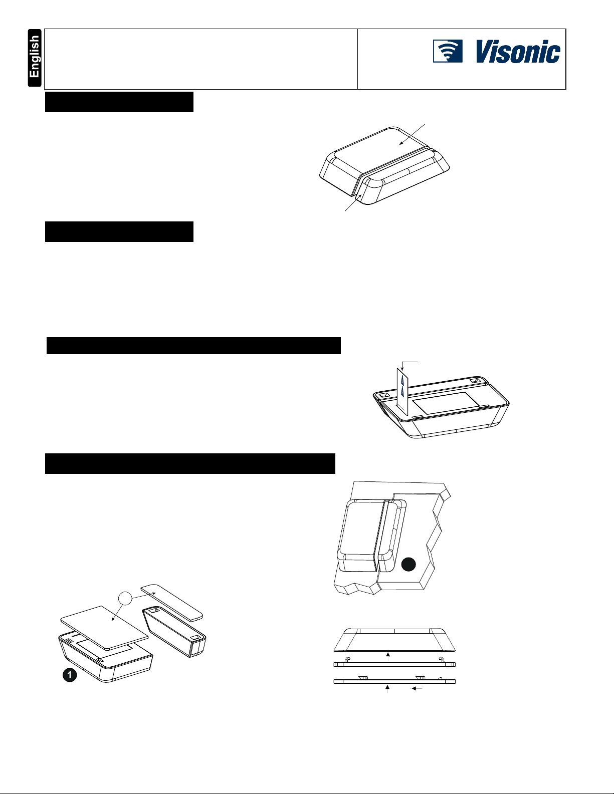
Fig. 4a – Opening Battery Cover
Fig. 4b –Replacing Battery
1. Press down on the battery cover and slide in the direction shown to
open it (see Figure 4a).
2. Push against the clip and lift the battery from the slot below it.
3. Insert the new battery into the sensor while observing battery polarity
(see Figure 4b).
4. Close the battery cover.
Note: The required battery is CR2450 Lithium 3V, manufactured by
Panasonic.
Caution! Keep the battery away from small children.
Caution! There is risk of explosion if battery is replaced by an
incorrect type. Dispose of used battery according to the
manufacturer's instructions.
6. REBOOTING THE SENSOR
You can reboot the sensor, as follows:
1. Remove the battery cover. 2. Press and release the tamper switch for 1 to 2 seconds.
3. Close the battery cover.
7. DEFAULTING THE SENSOR
CAUTION! The defaulting process removes the device from the network
and enables re-pairing.
Open the battery cover and pull back the clip to remove the battery (see
Figure 4).
1. Press and hold down the sensor’s tamper switch (see Figure 4b).
2. Insert the battery into the sensor while observing battery polarity (see
Figure 4b).
3. Release the tamper switch within 4 seconds. The LED will blink 3
times every 5 seconds to indicate successful default.
4. To re-pair the sensor, follow the instructions in section 3.
8. TROUBLESHOOTING
If you encounter one of the following problems with the MCT-350, do the
suggested remedy:
Problem Remedy
Attempt to pair the sensor
is unsuccessful. Make sure that the sensor has been defaulted
and is set to pairing mode (see section 7).
Make sure the security panel supports the
MCT-350.
The sensor and the panel
do not communicate. Perform the signal strength testing procedure
described in the security panel installation
manual. Make sure that the signal is sufficient.
If necessar
, replace the sensor’s batter
.
Problem Remedy
The sensor sends a Low
Battery indication. To ensure continuous proper operation, replace
the battery within two weeks of the first Low
Batter
indication
see section 5
.
Panel does not arm
because of an
unrecognized sensor
malfunction
Consult with your installer or system
provider before you disable a zone.
Disable the detector zone (see the security panel
user manual). Note that disabling a sensor zone
lowers the overall securit
level of
our s
stem.
9. COMPLIANCE WITH STANDARDS
USA/CANADA
FCC USA: CFR 47 part 15, Canada: RSS 247.
This device complies with Part 15 of the FCC Rules and RSS-247 of Industry and
Science Canada. Operation is subject to the following two conditions: (1) This device
may not cause harmful interference, and (2) this device must accept any interference
received, including interference that may cause undesired operation.
This device complies with IndustryCanada license-exempt RSS standard(s). Operation is
subject to the following two conditions: (1) this device maynot cause interference, and (2)
this device must accept any interference, including interference that may cause undesired
operation of the device.
Le présent appareil est conforme aux CNR d'Industrie Canada applicables aux
appareils radio exempts de licence. L'exploitation est autorisée aux deux conditions
suivantes : (1) l'appareil ne doit pas produire de brouillage, et (2) l'utilisateur de
l'appareil doit accepter tout brouillage radioélectrique subi, même si le brouillage est
susceptible d'en compromettre le fonctionnement.
FCC ID: WP3MCT350SMA5
IC: 1467C-MCT350SMA
USA/CANADA
Complies with:
ANSI/UL 634, ULC/ORD – C634
FCC Compliance Statement
This device has been tested and found to comply with the limits for a Class B digital
device, pursuant to Part 15 of the FCC Rules. These limits are designed to provide
reasonable protection against harmful interference in residential installations. This
equipment generates uses and can radiate radio frequency energy and, if not
installed and used in accordance with the instructions, may cause harmful
interference to radio and television reception.
However, there is no guarantee that interference will not occur in a particular
installation. If this device does cause such interference, which can be verified by
turning the device off and on, the user is encouraged to eliminate the interference by
one or more of the following measures:
– Re-orient or re-locate the receiving antenna.
– Increase the distance between the device and the receiver.
– Connect the device to an outlet on a circuit different from the one that supplies
power to the receiver.
– Consult the dealer or an experienced radio/TV technician.
WARNING! Changes or modifications to this unit not expressly approved by the party
responsible for compliance couldvoid the user’s authority to operate the equipment.
10. PRODUCT LIMITATIONS
Visonic Ltd. wireless systems are very reliable and are tested to high
standards. However, due to low transmitting power and limited range
(required by FCC and other regulatory authorities), there are some
limitations to be considered:
A. Receivers may be blocked by radio signals occurring on or near their
operating frequencies, regardless of the digital code used.
B. A receiver responds only to one transmitted signal at a time.
C. Wireless devices should be tested regularly to determine whether
there are sources of interference and to protect against faults.
The user is cautioned that changes or modifications to the unit, not
expressly approved by Visonic Ltd., could void the user’s FCC or
other authority to operate the equipment.
W.E.E.E. Product Recycling Declaration
For information regarding the recycling of this product you must contact the company from which you orignially purchased it. If you are discarding this product and not returning it for
repair then you must ensure that it is returned as identified by your supplier. This product is not to be thrown away with everyday waste.
Directive 2002/96/EC Waste Electrical and Electronic Equipment.
This device complies with the essential requirements and provisions of Directive 1999/5/EC of the European Parliament and of the Council of 9 March 1999 on radio and telecommunications
terminal equipment.
INTERNET: www.visonic.com
©VISONIC LTD. 2016 MCT-350
Rev 2, 3/16
Please refer to the se
arate Warrant
statement.
29009602R002