vissonic VIS-CRS02-A User manual

VIS-CRS02-A/CRS03-A/ CRS05-A
P
Pr
ro
of
fe
es
ss
si
io
on
na
al
l
C
Co
on
nf
fe
er
re
en
nc
ce
e
r
re
ec
co
or
rd
de
er
r
U
Us
se
er
r
M
Ma
an
nu
ua
al
l
V
Ve
er
rs
si
io
on
n
1
1.
.0
0

About the Manual
Type
No.
Product Versions
V1.0
Edited by
Jackson Huang
Updated Date
2019.4

Content
1.OVERVIEW ................................................................................................................................................................... 3
2.PRODUCT INTERFACE DESCRIPTION.................................................................................................................. 5
3. RECORDER DEBUGGING........................................................................................................................................ 5
4. FUNCTION AND OPERATION INSTRUCTIONS ................................................................................................................ 7
4.1 MAIN SCREEN............................................................................................................................................................... 8
4.1.1 Power on............................................................................................................................................................ 8
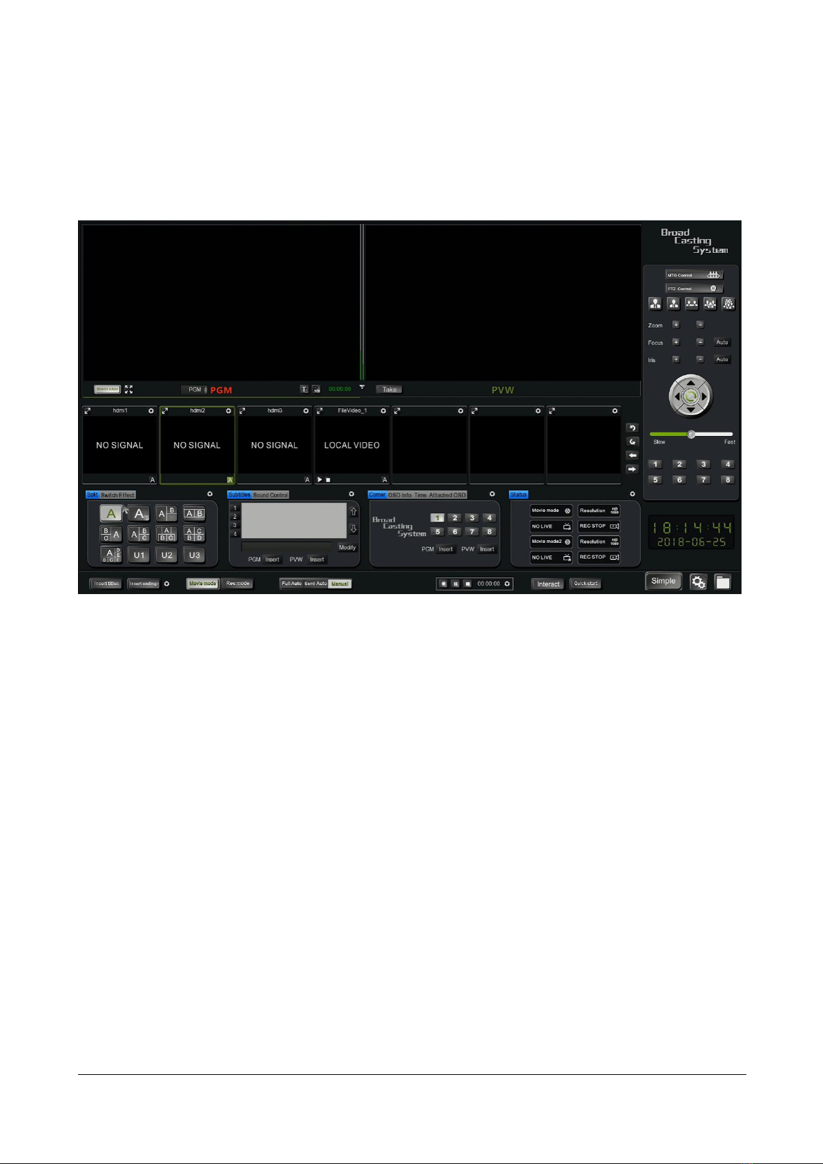
4.1.2 System Interface................................................................................................................................................ 9
4.2 MONITOR INTERFACE...................................................................................................................................................... 9
4.3 INPUT CHANNELS......................................................................................................................................................... 11
4.3.1 Input channels interface introduction............................................................................................................. 12
4.3.2 Input Channel setting ...................................................................................................................................... 13
4.4 CAMERA CONTROL ....................................................................................................................................................... 17
4.5 MEETING GROUP CONTROL(MGT CONTROL)................................................................................................................... 18
4.6 DIRECTOR FUNCTION .................................................................................................................................................... 21
4.6.1 Interface .......................................................................................................................................................... 21
4.6.2 Split-screen Processing.................................................................................................................................... 22
4.6.3 Subtitle and sound........................................................................................................................................... 23
4.6.4 logo/OSD information/time setting/additional OSD ....................................................................................... 24
4.6.5 Insert titles/Insert endings .............................................................................................................................. 25
4.6.6 Full Auto/Semi Auto/Manual direction ........................................................................................................... 26
4.7 SYSTEM FUNCTION ....................................................................................................................................................... 26
4.7.1 Recording control ............................................................................................................................................ 27
4.7.2 Interact button ................................................................................................................................................ 28
4.7.3 Quick Start....................................................................................................................................................... 28
4.7.4 Simple.............................................................................................................................................................. 29
4.7.5 System Setting; ................................................................................................................................................ 29
4.7.6 System Setting................................................................................................................................................. 39
4.7.7 File management............................................................................................................................................. 48
5 NETWORK GROUP.......................................................................................................................................................... 50

1.Overview
VIS-CRS03-A
VIS-CRS02-A
VIS-CRS05-A
Overview
VIS-CRS03-A/VIS-CRS02-A conference recorder is the latest generation of recording and
broadcasting equipment independently developed for the needs of small and medium-sized
enterprise conference rooms, training rooms and mobile recording and broadcasting.
Features
⚫Recorder is integrated, based on the embedded hardware architecture design with highly
stable.
⚫H.264 encoding, 3 HDMI/2HDMI video input interfaces and 1 HDMI video out or direction
interface out
⚫Supports simultaneous recording and live broadcast of the movie mode + resource mode.
⚫The picture supports picture-in-picture, 1/2/3/4//6 split-screen mode display and recording.
⚫The user can connect the mouse and display for operating the built-in recording software
⚫Web recording interface is supported
⚫The video supports max.4K@30fps resolution for input,recording and output.

Specification
Model
Specification
VIS-CRS02-A/VIS-CRS03-A/ VIS-CRS05-A
System structure
Embedded Linux operating system
Operation interface
Graphical menu operation interface
Language
English and Chinese
Input interface
3 HDMI for VIS-CRS03-A, 2 HDMI for VIS-CRS02-A
Output interface
1 HDMI for live or broadcast and recording operation interface
Video display mode
Full screen,PIP,1/2/3/4/6 split screen
Max. input frame
4K@30 frame
Input Resolution
HDMI:1024*768p@60fps,1280*720p@50/60fps,
1920*1080i@60/50fps,1920*1080p@30/25fps,1920*1080p@60/50f
ps,4K@30fps(for VIS-CRS05-A)
Output Resolution
Max. 4K@30fps for VIS-CRS05-A
Max. 1920*1080p@60/50fps for VIS-CRS02-A, VIS-CRS03-A
Audio Input
2x line-in
Audio Output2
2x line-out,1x 3.5mm earphone
Audio encoding
AAC
Audio Recording way
Audio is recorded along with video
Video encoding
H.264 High Profile
Recording file format
MP4
Video coding frame rate
1~30fps
Video code rate
50kbps~40Mbps adjustable
Audio code rate
8KB~420KB adjustable
Storage
Built-in 1TB hard disk,support extensions
RS485 interface
4 ports,RJ45
RS232 interface
2 ports,RJ45
RJ45 network port
1 Network port support 802.3ab 1000Base-T Gigabit Ethernet
network interface
Console port
Standard console port for testing
USB
1 USB2.0 and 1USB3.0(For mouse,U disk and directed video switcher)
Control and Management
Front Panel
WEB
HDMI output + USB Mouse
RS232/RS485 for console or central controller
LAN
Video-live-broadcast and video-on-deman
d
RTSP standard data stream live
RTMP standard data stream live
TS multicast stream data push
Local decoding preview playback
Network protocol
Support RTMP、RTSP、UDP、TCP、FTP、DHCP、HTTP
Update
By TCP/IP or RS232
Size
440mm × 270mm × 44mm
Weight
2kg
Operating temperature
-20ºC ~ 60ºC
Relative humidity
5% to 95%
Storage and transport temperature
-40ºC ~ 80ºC

Operating voltage
DC 12V
Operating Current
9.2A
Power
70W
2.Product interface description
Figure 1 Rear panel interface diagram
The rear panel interface is defined as follows:
SN
Interface
Instruction
1
DC-12V
Device power interface
2
USB3.0
Connect USB mouse, USB flash drive, mobile hard drive, etc.
3
NET
1000M network port for device networking
4
USB2.0
Connect USB mouse, USB flash drive, etc.
5
HDMI-OUT-2
HDMI signal output, output screen is the guide interface or PGM
(software can be set)
6
HDMI-OUT-1
HDMI signal output, output screen is the guide interface or PGM
(software can be set)
7
HDMI-IN-1-3
HDMI signal input, support 2/3 channels(depend on model) of 4K
video signals simultaneously input
8
LINE IN/OUT
Audio input and output interface, IN means input, OUT means output
9
Monitor
3.5mm headphone monitor interface, monitor PGM channel sound
10
COM/Console
RS232/RS485 control serial port
3. Recorder debugging
1)Preparation before debugging
Before installing and debugging the recorder, please prepare the following:
1) The network cable and switch can also be connected to the Hub. It is recommended to use the switch

to keep the network flowing.
2) Power cable*1, HDMI cable*4, audio input and output cable (LINE-IN,MIC-IN, LINE-OUT, monitor
headphones, etc.)
3) External HD display, one HDMI interface, resolution is 1920×1080.
4) Prepare a laptop and several HDMI camera cameras as input sources.
2)Debugged wire connection
1) Please connect the HDMI video signal cable, audio signal cable, network cable, RS232/RS485 control
cable, power cable, USB mouse, etc. to the corresponding interfaces, and make the corresponding audio and
video input and output connections.
2) After confirming that the recording host is properly connected to the power supply, then press the
power switch of the navigation panel to start the recording host. After the device is powered on, it can wait
for about 30 seconds to enter the navigation interface to manage the system.
Notice
The HDMI-OUT-2 interface outputs the system interface (guide interface) of the recorder. The user can
connect the USB mouse and the keyboard to the recorder to perform corresponding operations. Live video
(PGM1 or PGM2) output from the HDMI-OUT-1 interface. The recorder is a static IP and the IP address is
192.168.100.66.

4. Function and operation instructions
Main Screen
Main screen is including 5 modules: Monitor interface, Video channel, Camera control, Program,
System configuration
(1)Monitor Interface:program in film mode, preview or broadcasting (PGM、PGM2、PVW)
(2)Video Channel:display the input video
(3)Camera control:to control the camera manually
(4)Program panel:functions for effects/scripts/logo/OSD information/Program mode
(5)System configuration:All settings for recording, system and file management

The detailed function structure tree is shown in Figure 3 below.
Figure 3 Function Structure
4.1 Main Screen
4.1.1 Power on
Press the power button on front panel to power on the system. The display connecting to HDMI OUT 1 and
monitor on controller will show the booting logo. (The logo can be change by entering system setting - system

information - project setting)
4.1.2 System Interface
After around 20 seconds, you will see the main system interface.
Figure 9 Main Screen
4.2 Monitor Interface
Including:
1.PGM and PVW in Movie mode
2. PGM and PGM2 in Res mode
3.Audio Bar
PGM and PVW on Movie mode:

Figure10 PGM and PVW
PGM and PGM2 on Res mode:
Figure11 PGM and PGM2
Description:
1. Both the Single-director mode and the Dual-director mode are movie modes. Both modes support
the main picture overlay and combination:
Picture-in-picture, dialogue mode, 2/3/4/6 split screen. In the Single-director mode, the live picture PGM and
the preview monitor PVM are included. In the dual-director mode, two live broadcasting video PGM and PGM2
are included.
2. when the Single-director and Dual-director is in the Full Auto mode, only supports PGM channel
image automatically switch. When directing under Dual-director mode and Manual mode,it could manually
switch the output (device HDMI-OUT-1 output), HDMI-OUT-1 output video can be changed from PGM channel
picture or PGM2 channel picture, you need to manually select the button ‘Director output’ on the lower left
window.
3. In Single-director mode can select the video display by PGM or PGM2
4. The Audio Bar is located between the PGM channel and the PVW channel in the single-director
mode, and between the PGM channel and the PGM2 channel in the dual-director mode, there are two small

audio bars. Audio bar is mainly reflected the volume of the audio input; the green wave will vary with the
volume of the sound. Click the Menu ‘Sound Control’ can adjust the volume of input for recording and output to
speaker system or HDMI out, also click on or mute the sound.
5. In the PGM and PGM2 mode, you can click the button to perform the following quick operation: TS
multicast push, RTMP push, and start, pause, and end of recording. (Streaming Media Server IP or TS
broadcasting address must be set in the setup before pushing the stream). TS multicast push button,
RTMP push button, start local video record, pause button, stop record button.
6. When working under Semi Auto or Manual mode, you double-click the preview PVW image, the
image jumps to PGM and overwrites the previous one. For example, PVW preview is a 2-screen image, PGM is a
6-screen image, double-click the PVW channel, 2-screen image cut to PGM, the original 6-screen image is
replaced. PVW and PGM, PGM2 are all support multi-screen combination. If working under Full Auto, you
double-click the PVM screen, only make you get the full screen image..
Procedure: After selecting the PGM ,PGM2 or PVW channel, select the type of screen division, and then select
the combined position of each channel in the video input channel.
7. In the single-director mode, PVW window has a 'Take' button, it’s hardware switch function, click
the button 'Take', the PVW channel image directly switch to the PGM channel. The system, provide 3 kinds of
action mode for options. You can select from system setting menu. and last sub-menu. You get three
options: 1, Default: the mouse activates the PVW or PGM channel, then double-click the channel to the
corresponding resource channel; 2, PGM: double-click the resource channel to switch the video image directly to
the PGM channel; 3, PVW: double-click the resource channel to switch the video image directly to the PVW
channel, and then click the [take] button to switch the PVW channel image to PGM.
4.3 Input Channels
Video input channels,as following picture indicates

Figure12 Video input channel
Video input channel is divided into three parts: the local video display channel,local playback
channel and remote video display channel.
Each recording and playback host can display video locally, such as PGM, PVW, PGM2, and Input
channels, and can add remote recording image from Conference Control menu and display it in Input
Channels, PGM and PVW channel.
The first channel (display name:HDMI1 on the channel)and second channel(hdmi2) is corresponding to
the HDMI port 1 and port 2 of local recorder.(If model VIS-CRS03 and VIS-CRS05,then more HDMI
inputs are available and so forth..) For example, We use the VIS-CRS02 as the conference recorder, its
HDMI1 connect to the camera and HDMI2 connect to a PC of speaker. The third input channel display
the local replay video. If you connect the remote conference recorder(like VIS-CRS02),the remote video
will display at the fourth input channel. Each conference recorder can connect to several remote video
channels. The remote image and sound can be transmitted together and also can be switch to
PVM,PGM and PGM2 to push stream and recording etc. Multi-conference room communication ,two or
more conference recorder need to be connected to the network
4.3.1 Input channels interface introduction
1. Full Screen---Each input channel display a full screen item ,click the item and get maximum image
on the main screen.
2. Channel Name---The default channel name are hdmi1,hdmi2,hdmi3...(according to
model),"FileVideo_1".The channel name can be changed from the channel setting on each channel
interface.
3.Camera Control---If the input channel is connected with PTZ camera. You need to enable the PTZ
function from the channel setting . Select the option 'Enable' and you can control the camera from
camera control interface under channel setting menu.

4.Local replay video---The input channel 3 names 'FileVideo_1' and is for replay the local video. Click
and into its channel setting. Click the 'Select File' to browse the hard disk or USB storage devices to
select the video file "*.mp4",click 'apply' and 'OK'. Back to the input channel interface, click the to
play the video and to stop playing. The local replay image also can be switch to the PGM channel to
live broadcast.
4.3.2 Input Channel setting
There are a channel setting item on each channel. By the channel setting, we can set the video
parameter for current channel. The setting is included sub-menu, 'Channel', 'PTZ', 'Picture' and 'Codec'.
as the bellowing,

4.3.2 channel setting interface
4.3.2.1 Channel
1. Monitor—the default channel number
2.Video Format—Display the current video format and it can be changed under Codec submenu.
3.Channel—The name of current channel and can be changed the name according to the source for
easily identification.
4.Auto Switch---Select the Auto Switch ID for the current channel and it work with the switch strategy.
5.Disp Mode---Provide the ratio and full screen. If the video from the current input channel can't display
full screen on PGM. You can change the display mode setting.
6.Source—Corresponding to the hardware input number.

4.3.2.1 PTZ
1.Enable PTZ---to enable the camera control function
2.Protocol--Support VISCA,PELCO-P,PELCO-D protocol
3.COM--The interface for PTZ camera or camera tracking controller connect to conference recorder,
support RS485 and RS232,corresponding the RJ45 port.
4.Baud Rate---support 2400/4800/9600 and set it according to the specification of the camera.
5.Address Code-- The address code should be the same as the camera setting.
6.Speed---Set the speed of camera turning.
7.Preset-You can select the 1 to 8 preset and extreme closeup, closeup, close-range, mid-range,
perspective. The preset of extreme closeup is 11, closeup is 12, close-range 13, mid-range

13,perspective is 14. The user just select the preset, adjust the camera to the needed position and save
the preset. When operating, we just select the preset.
8.PTZ operation--Click the button , , ,to turn the cameras. Zoom + ,- to change the zoom
big and zoom small. Focus +,- to focus the close or remote items.
Iris +,- to adjust the Iris size.
Note: 1.The connection of camera to recorder or camera tracking controller to recorder must be
corrective.
2.The setting of camera protocol, baud rate, address code input channel under channel input need to be
the same as camera.
3.Only under the Manual mode, the setting of PTZ on channel PTZ setting or main screen PTZ setting
are valid.
4. Selecting the 'Enable PTZ' on setting of input channel is a must to operate the PTZ setting on main
screen
4.3.2.3 Picture
The setting include the brightness, contract, chroma, Satura ,noise reduction. The video quality is mainly
dependent on the specification of camera. Normally, it is no need to adjust the parameters.

4.3.2.4 Codec
1.Resolution:Major Code:1920*1080、1600*900、1280*720、960*540 etc; Sub stream:960*540、
640*360、480*270、720*576、352*288.
Note :
Under rersouce mode,the multi stream and multi screen,the channel recording are setted as these resol
ution and code rate.
2.code format:H.264
3.Code Rate:adjustable range 50Kbps~40Mbps, default main stream rate is 4000Kbps,sub stream c
ode rate:400Kbps
4.Picture quality level:0 to 5 ,0 level is the best.
5.Frame rate:10 to 60 frame, default set is 25 frame.
6.GOP: time settable ,default is 30s.
4.4 Camera control
PTZ control function is the same as channel settings . The ,,,is to control the direction, "+" And
"-" are zoom in and zoom out function keys, and the focus "+" and "-" buttons are Focusing on distant objects
or close objects. [Aperture] "+", "-" is adjust large aperture or the small aperture.
In the channel PTZ setting, you can set the preset position of 1-8, then you can recall the position and
switching them.

Figure 17 Camera control
4.5 Meeting Group Control(MGT Control)
Tne local conference recorder connect to the remote recorder and get the remote audio/video to add to the
local input channel .and display on the local screen.
Application example, 1 conference room as the main conference room and other conference room connect
to the main conference room and get the audio/video from main conference room.
NOTE: All the recorders should be under the same local area network.

Click the MTG Control
Get the interface as
This manual suits for next models
2
Table of contents