Vista 5275 User manual
INSTALLATION INSTRUCTIONS In-Ground and Well Lights
1625 Surveyor Avenue • Simi Valley, CA 93063 • (805) 527-0987 • (800) 766-VISTA (8478)
FAX: (888) 670-VISTA (8478) • [email protected] • www.vistapro.com
12V SERIES
FOR USE ONLY WITH LOW VOLTAGE LANDSCAPE POWER UNITS THAT DO NOT EXCEED 25 AMPS, 15 VOLT MAXIMUM.
WARNING: Luminaires must be installed in accordance with the National Electrical Code (NEC) and local codes.
Failure to do so will void the warranty and may result in serious injury and/or damage to the luminaire.
SAFETY WARNING: Luminaire can become very hot depending on lamp wattage used. Lens and metal around
lamp can become hot enough to blister hands. Particular care should be taken not to locate luminaires where
small children can reach them if high wattage lamps are used.
LUMINAIRES ARE NOT TO BE INSTALLED WITHIN 10 FT. (3.05M) OF A POOL OR SPA. SECONDARY CABLE IS NOT TO
BE BURIED MORE THAN 6”. WHEN USING MULTIPLE LUMINAIRES, LOAD IS NOT TO EXCEED THE TOTAL WATTS OF
TRANSFORMER RATING. DO NOT USE EXTENSION CORDS ON POWER UNITS.
NOTE: Always use UL recognized wire connectors for connections.
NOTE: Save these instructions for future reference.
LUMINAIRE IS UL LISTED FOR BELOW GRADE INSTALLATION ONLY.
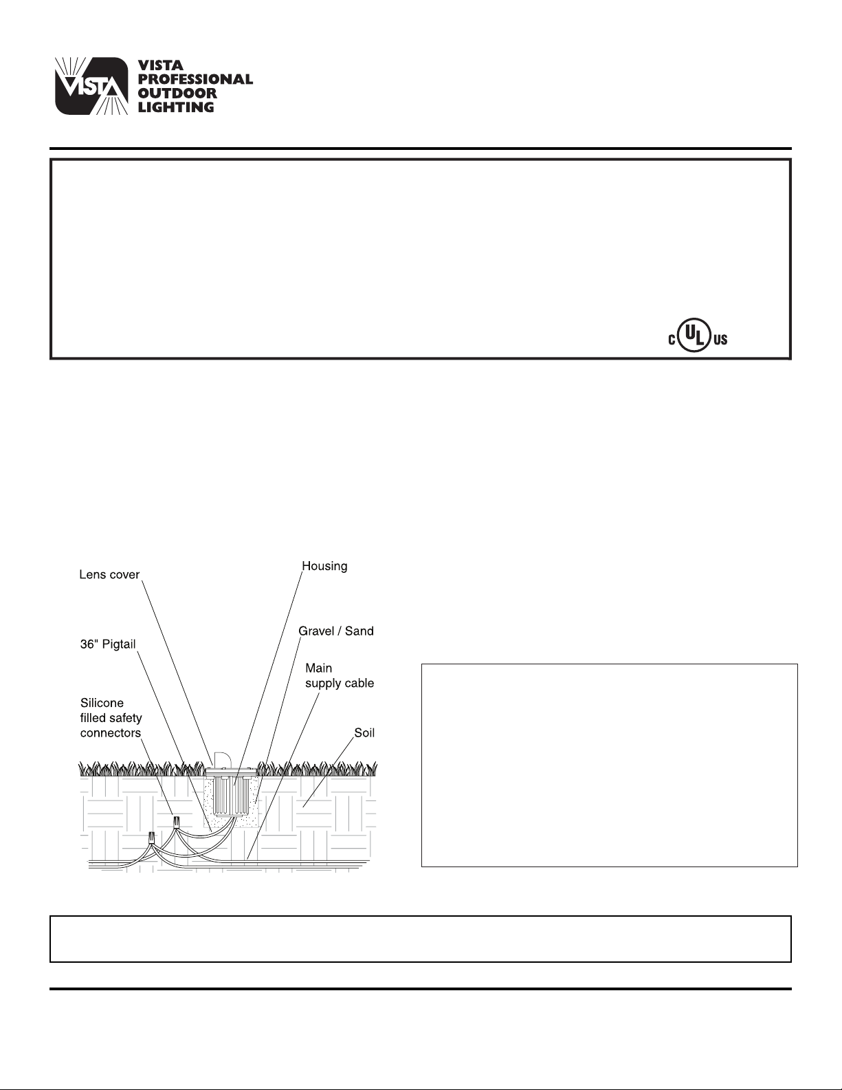
LUMINAIRE MOUNTING:
PRECAUTION: Luminaire is not submersible and adequate
drainage must be provided during installation. It is
recommended that the luminaire be surrounded by 3” to
4” of pea gravel or sand to assure proper drainage. Top of
luminaire must be above grade so rain and irrigation water
can not accumulate for long periods of time.
1. To prevent electrical shock, disconnect transformer from
electrical supply before installation or service.
2. Dig hole approximately 10” diameter by 8” deep. This
allows approximately 3” of pea gravel or sand to surround
the luminaire housing.
3. Strip the (2) leads from the luminaire pigtail wire. Using
the two (2) silicone lled safety connectors (provided),
connect the leads from the luminaire to the electrical
supply wire leads.
NOTE: Luminaires are supplied with 36” of 18-2 cable pigtail
for secure connection to the electrical supply cable. The
wire is to be protected by routing in close proximity to the
luminaire. The wiring shall be buried a maximum of 6
inches (15.2 cm) in order to connect to the electrical
supply wire.
4. Install luminaire in hole and backfill hole after installation
with pea gravel or sand.
5. Provide power to luminaire and check for proper
operation.
In-Grade Soil Installation:
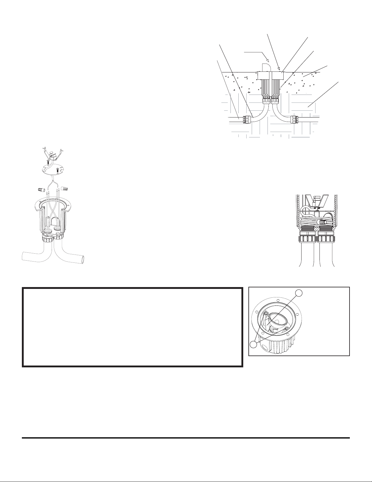
Concrete Pour Installation:
NOTE: Due to the temperature requirements in the wiring compartment, UL listed THHN stranded copper electical wire is recomended for
electrical supply wires.
LED FIXTURE INTALLATIONS:
For each low-voltage LED luminaire, the Vista-designed
electronic driver ensures the LED operates at the intended
Lumen output while receiving voltage as low as 6, and
as high as 15 VAC for balanced lumen output from the
first fixture to the last, with no voltage drop issues to affect
your installation. Also, instant-start functionality with full
color, 100% light, and cold-start capability down to -40
degrees Celsius.
NOTE: The operating voltage range for LED fixtures is
6-15V AC. Exceeding the maximum voltage (15V) could
result in damage to internal components and void the
manufacturer warranty.
continued on next page...
5275
stranded copper electical wire is recomended for
electrical supply wires.
8. Make wire connections to luminaire as required using the
safety connectors provided.
9. Coil wire leads along bottom of fixture and close wiring
compartment as shown in fig. 4.
10. Pour concrete at least 2” thick.
11. Install lamp with correct
wattage and type marked
on the fixture label and set
lamp at desired aiming
angle.
12. Replace silicone rubber
gasket, lens, and cover,
and tighten screws evenly.
NOTE: Failure to remove all dirt
and debris from gasket
sealing surface
may cause leakage and
1625 Surveyor Avenue • Simi Valley, CA 93063 • (805) 527-0987 • (800) 766-VISTA (8478)
FAX: (888) 670-VISTA (8478) • [email protected] • www.vistapro.com
LUMINAIRE MOUNTING:
1. To prevent electrical shock, disconnect transformer from
electrical supply before installation or service.
2. Dig hole approximately 10” diameter to a depth suitable
to make top of fixture flush to 1/8” above grade. Pea
gravel or sand is recommended for seating the luminaire
housing to aid positioning.
3. Install JBCP-150 concrete mounting guard making sure
the top edge of the ring lines up with the top edge of the
lens cover. Secure side bands to the bottom of fixture with
#10 screws provided. (Side bands of JBCP-150 may be
bent outward to adjust the fit of the top ring.)
4. Remove lamp assembly and wiring compartment cover,
exposing conduit entry holes.
5. Install conduit through 3/4” NPT holes in bottom of
luminaire using Teflon tape or other thread sealant. Using
plug (provided), seal unused conduit entry if required.
NOTE: UL listed flexible conduit is recommended for in and
out connections to ease fixture position and adjustment
during installation.
6. Support luminaire in selected
position using standard masonry
procedures.
NOTE: When installing in concrete,
JBCP-150 must be flush to 1/8”
above grade to promote water
runoff.
7. Pull electrical supply wires (line
in) through conduit and
luminaire. Pull wires long enough
for manual connections with
safety connectors (4” to 6”
above the top rim of luminaire).
See fig. 3.
NOTE: Due to the temperature
requirements in the wiring
compartment, UL listed THHN
CAUTION: Do not exceed maximum wattage marked on
luminaire label.
1. To prevent electrical shock, disconnect transformer from
electrical supply before service.
2. Loosen cover screws and remove cover.
3. Remove gasket.
4. Replace lamp with correct wattage and type marked on
fixture label.
NOTE: DO NOT touch Halogen lamp with bare hands.
Always use soft cloth or the plastic wrapping (if available)
from the lamp to handle the lamp.
5. Clean gasket and channel and re-install gasket.
6. Re-install cover and tighten the cover screws evenly.
IMPORTANT SAFETY INSTRUCTIONS
THE LIGHTED LAMP IS HOT!!
WARNING: TO REDUCE THE RISK OF FIRE, OR INJURY TO
PERSONS:
1. Turn off/unplug and allow to cool before replacing lamp.
2. Lamps get hot quickly! Contact only switch/plug when turning on.
3. Do not touch hot lens, guard or enclosure.
4. Keep lamp away from material that may burn.
5. Do not touch the lamp at any time. Use a soft cloth. Oil from the skin may damage lamp.
6. Do not operate luminaire tting with a missing or damaged cover.
SAVE THESE INSTRUCTIONS
NOTE:
Lamp bracket may
be adjusted for
lamp aiming. Loosen
bracket screws (1),
then manually tilt
bracket (2) to desired
position. Tighten
bracket screws
afterward to secure
lamp position.
1
2
g. 3
LAMP INSTALLATION/REPLACEMENT:
g. 4
5275 (4/06)
Lens
Stainless
steel screw
Rigid conduit
Concrete
pour kit
Flexible conduit
(Recomended)
Fixture housing
Concrete
Soil
Other Vista Lighting Equipment manuals


