VISTEK V1651 User manual

1
VISTEK V165XSERIALDIGITAL
VIDEO ROUTERMODULE
USER GUIDE
www.pro-bel.com

VISTEKV165X serial digital
video routermodule
2Issue1
Contents
1. INTRODUCTION........................................................................................................3
1.1 Description.......................................................................................................3
2. INSTALLATION.........................................................................................................4
2.1 Rear Panel Connections.................................................................................4
2.2 Hardware..........................................................................................................5
2.2.1 Switch and LinkSettings.......................................................................5
3. OPERATION..............................................................................................................9
3.1 Front Panel Indication.....................................................................................9
3.2 Indicators.......................................................................................................11
3.3 Controls..........................................................................................................12

VISTEK V165X serialdigital
video routermodule
HU-V165X 3
1. INTRODUCTION
1.1 Description
The V165XSerial Digital Video RouterModule providesa platformon which several different typesofrouter
maybe built. All the variantscan handle the fourmain video standard frequencies of143, 177, 270 and 360
Mbits/s. The outputs are fullyre-generated.
The range consistsof :-
The V1651 2x1 SDI routerwith automatic signal errordetection and changeover.
The V1652 8x1 SDI router.
The V1653 8x1 SDI routerwith synchronousswitching.
The V1654 8x8 SDI routerwith Output monitoring.
Allthe routerscan be fed with an analogue external reference signal, but thisreducesthe 8x1 routers to
7x1'sdue to the limited rear panel space. Ifthe external reference is not fitted the switching reference will be
taken fromthe currentlyselected output, so vertical interval switching will be maintained between sourcesof
the same relative timings. The switching line used is userselectable and maybe field or frame based.
The routersare allprovided with front panel controls and indicators. Allthe modulesare provided with the
required interface logicforthe Dart remote control systemand also a simple remote panel interface. (See
V1650 Remote Control Manual).
The V1651, 2 & 3 modules are 3U high cardsand are designed to fit in the V1601 orthe V1603 racking
systems. The V1654 isalso 3U high modules, but isdouble width, so will onlyfit in the V1603 rack.
The V1651 and V1653 aredesigned to have clean switching between the sources.The routersachieve this
bytiming the newsourceas close to the referenceaspossible, before switching. The reference is obtained
fromeither the External Referenceinput (I/P 8), orif not present the currentlyselected source. (The V1651
mayhave itsclean switching turned offifa reference is not available.)
Due to the sources having differing clockphasesit isonlypossible to synchronise the sourceswithin one
clockcycle, so ifthe reference istaken fromthe sources rather than an external reference the delaythrough
the router can progressively change assources are selected.

VISTEKV165X serial digital
video routermodule
4Issue1
2. INSTALLATION
2.1 Rear Panel Connections
V1651 V1652, V1653 V1654
Power
The power is picked up bythe input connector panel fromthe frame to feed the router. The nominal power
consumption ofeach router is:-
V1651 8.5W
V1652 6W
V1653 10W
V1654 13.5W
Ifthe V1650 Remote Control Panel Interface isconnected the power consumption of the router module is
increased by0.5W.
SD1-8 (IN)
The Serial Digital Inputsare passed straight through the rear module and terminated in 75 Ohms on the main
module. Input 8 on the V1652 and V1653 isshared with the reference input and a zero ohmresistorisfitted
on the module to set the operational mode. (R102 - I/P 8, or R103 - Ref). Inputs 2, 4, 5, 6 & 7 are not used
on the V1651 and input 8 isset on the main module to the reference mode.
SD
(OUT)
SD1
(IN)
SD2
(IN)
SD3
(IN)
SD4
(IN)
SD6
(IN)
SD7
(IN)
SD8
(IN)
/REF
SD1
(IN)
SD2
(IN)
SD3
(IN)
SD4
(IN)
SD5
(IN)
SD6
(IN)
SD7
(IN)
SD8
(IN)
MON
(OUT)
SD1
(OUT)
SD2
(OUT)
SD3
(OUT)
SD4
(OUT)
SD5
(OUT)
SD6
(OUT)
SD7
(OUT)
SD8
(OUT)
REF
SD
(OUT)
SD1
(IN)
REF
SD2
(IN)

VISTEK V165X serialdigital
video routermodule
HU-V165X 5
REF
The referenceinput is an analogue video signal of either1Vp-pvideo or upto 4Vp-pmixed sync pulses.The
signal is passed through the rearmodule and terminated in 75 Ohms on the input router module.
SD (OUT) & SD1-8 (OUT)
The outputsare driven directlythrough the rear module fromthe input or output router module at 75 Ohm
impedance.
MON (OUT)
The monitoring output isdriven directlythrough the rearmodulefromthe input router module at 75 Ohm
impedance. This output monitors the output bussesof the crosspoint ic and not the inputs to the crosspoint.
DARTRemote Control
The DARTcontrol interfaceispicked up bythe input rear module fromthe rackand routed into the input
router module.
2.2 Hardware
The figure below shows diagramaticallythe input module, whichcontainsall the control hardware and link
selectable variations.Not all componentsare fitted in everyvariant, (see text for details). The 8Output
module hasno links and istherefore not shown.
2.2.1 Switch and Link Settings
R102 & R103
These two resistorsare used to control the routing ofthe signal on input eight to determine if the reference is
used orSDI input eight. The modulesare shipped in the following configurations:-
V1651 R103 Reference Input.
V1652 R102 SDI Input eight.
V1653 R103 Reference Input.
V1654 R102 SDI Input eight.
FRONTPANEL
EC2
SW11
a b c a b c
LK
LK2
1
8
SW12
REAR CONNECTOR
R102
R103

VISTEKV165X serial digital
video routermodule
6Issue1
The V1652 and V1653 maybe changed to allowareferenceto be used forswitching timings or input 8. To
change the mode move R102 or R103 to the other position. (A surface mount resistor isused rather than a
linkto reduce the signal degradation ofthe SDI signal).
The V1651 and V1654 do not require changes to be made as the signal pathsare not required for dual
purpose use.
LK1
Link1 controlsthe switching frequencyof the router between Frame rate and field rate.
LK2
Link2 isused to tell the control systemwhich signalsare used to obtain the switching reference timing. Ifthe
linkisset to INT. (Internal) the switching reference timing will be taken offthe currentlyselected video output,
or in the absentsofa signal the free running clock. When the linkisselected to EXT(External) the switching
reference timing is taken fromthe REF. input, but in itsabsentsthe router reverts to using the currently
selected output or the free running clock.
The linkisalsoused on the V1652 and V1653 to instruct the control systemas to the numberofavailable
SDI inputs. With the linkset to INTthere are 8 selectable inputs, but with the linkset to EXT there are only7
and the source button eight is ignored bythe control system.
Note: If the V1654 isrunning off internal reference the signal used forswitching timing is the currently
selected monitoring output, selected by the local destination panel.
SW11
Switch 11 is used to assign the line on which the router will switch. (See table below)
625
Lines
525
LinesSW11
LK1 FRM LK1 FLD LK1 FRM LK1 FLD
0621 621 & 309 525 525 & 263
1622 622 & 310 11 & 264
2623 623 & 311 22 & 265
3624 624 & 312 33 & 266
4625 625 & 313 44 & 267
511 & 314 55 & 268
622 & 315 66 & 269
733 & 316 77 & 270
844 & 317 88 & 271
955 & 318 99 & 272
A66 & 319 10 10 & 273
B77 & 320 11 11 & 274
C88 & 321 12 12 & 275
D99 & 322 13 13 & 276
E10 10 & 323 14 14 & 277
F11 11 & 324 15 15 & 278

VISTEK V165X serialdigital
video routermodule
HU-V165X 7
SW12
Switch 12 is onlyfitted on the V1651 and the V1653 and can be divided into two halves. The switches 1-4
control the synchroniserdelayforboth routersand the switches 5-8 are used bythe V6151 to determine the
conditionsfor an automaticchange over of sources.
Switch 1 (V1651 only)
This switch turns offthe synchronising function and reduces the delayof eachchannel to aminimum. This is
the recommended mode ofoperation if an external reference is never provided.
Switches 2-4
Theseswitchescontrol the amount ofdelayadded to the signal path with respect to the referencesignal
being used. This will allow the synchronising mechanismto timesignalsearlyon the referenceupto 4000
clockcyclesminusthe selected delay, or late on the reference upto the selected delay. (See table).
Approximate selected delays. (wrt selected reference).
SW12 Approx.Delay(us)
2 3 4 143Mbits/s
177Mbits/s270Mbits/s360Mbits/s
0n 0n 0n -179, +0.7 -225, +0.5 -147, +0.5 -109, +0.3
0n 0n 0ff-177, +3 -224, +2 -146, +1.5 -109, +1
0n 0ff 0n -173, +7 -220, +6 -144, +3.5 -107, +3
0n 0ff 0ff-264, +16 -213, +13 -139, + 9 -104, +6
0ff 0n 0n -245, +35 -197, +28 -130, +18 -97, +13
0ff 0n 0ff-210, +70 -169, +56 -111, + 37 -83,+27
0ff 0ff 0n -175, +105 -142, +84 -93, +55 -69, +41
0ff 0ff 0ff+140 +113 +74 +55
* WARNING * Careshould be taken when setting the delay,aspicturedisturbanceswill occurif the
FIFO minimumor maximumlengthsare reached.
Switch 5 (V1651 only)
Thisswitch allowsthe unit to selectbetween synchronous and Non-synchronous switching modes according
to whether an external reference ispresent and being used. Ifthe unitslink2is in EXT and areference is
provided the router will operate with synchronous switching. If link2isset to INTor the referenceisnot
present the unit will change to non-synchronousmode automatically.

VISTEKV165X serial digital
video routermodule
8Issue1
Switches 6-8
These switches are onlyused on the V1651 to set up the operation of the automaticmode.
Switch 6 on Lock Fail
Sets the fail condition to occurwhen the currentlyselected source doesnot
lock up the re-clockeric.
Switch 7 on EDH Fail
Sets the failcondition to occurwhen multiple EDH errors are detected. An
errorcondition will be set if3 fieldscontaining EDH errorsare detected
within 32 fields and cleared once 32 consecutive errorfree fields are
present.
Switch 8 on HOLD
Sets the router to change sourceswhen the current source fails,providing
the othersource isgood, when in AUTO mode.
off FLIP/FLOP
Sets the router to alwaysselect input 1ifsource 1is good, when in AUTO
mode.
VISTEK V165X serialdigital
video routermodule
HU-V165X 9
3. OPERATION
3.1 Front Panel Indication
The REM lamp indicatesthat the DARTcontrol systemcommunications
linkis active.
The +V lamp indicates that powerisapplied to the module.
The 270 lamp indicates that a 270Mbit/sITU-R Rec.601 serial component
video source is selected.
The 360 lamp indicates that a 360Mbit/sITU-R Rec.601 serial component
video source is selected.
The 143 lamp indicates that a 143Mbit/sITU-R Rec.601 serial composite
video source is selected.
The 177 lamp indicates that a 177Mbit/sITU-R Rec.601 serial composite
video source is selected.
The EDA lampindicates an error in the Serial Video Signal whichwas
detected prior to thisunit. (Errordetected already).
The EDH lampindicatesan error in the Serial Video Signal whichwas
detected bythisunit. (Errordetected here).
The Ref.Select button is recessed behind the front panel and isused to
re-time the output on the V1651 and V1653 only.
Source 1-8 Local selection ofinput source.
Rem Remote control via the Dart control Interface.
+All router source selection controls are inhibited.
Loc. Local control fromthe front panel and the V1650 Remote Control
Panel Interface.
REM
+V
270
360
143
177
EDA
E
DH
Ref.
Select
Source
1
2
4
6
8
7
5
3
-
+
Local
REM
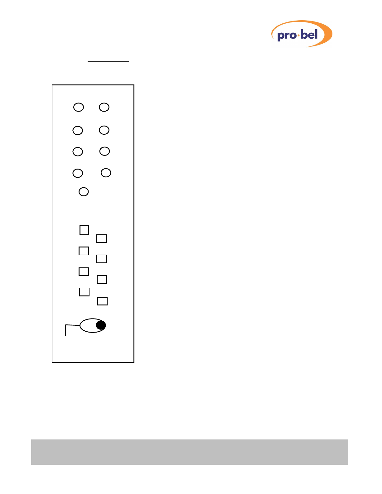
V1653

VISTEKV165X serial digital
video routermodule
10 Issue1
REM +V
270 360
143177
EDAEDH
Rem
Local
+
Auto
Ref.
Select
V1651
REM +V
270360
143 177
EDA EDH
Rem
Local
+
Source
1
2
3
4
5
6
7
8
V1652
REM +V
270360
143 177
EDA
EDH
Rem
Local
+
Source
1
2
3
4
5
6
7
8
V1654
Destination
1
2
3
4
5
6
7
8
Fail
Fail
-

VISTEK V165X serialdigital
video routermodule
HU-V165X 11
3.2 Indicators
REM
The REM (Remote)indicator illuminateswheneverthe module is accessed bythe DARTcontrol system.This
will occur even if the module is underlocal control.
+V
Thisindicates that the module ispowered and producing itsinternalvoltage rail.
270, 360, 143, 177
When a source is routed through the unit the indicators will show the video frequencystandard ofthe locally
selected output, provided the signal islocked in the reclocking ic. Ifno indicators are on then the signal has
not locked up in the reclocker.
EDA, EDH
These indicators are used to displayErrorsthat are detected within certain checksumsembedded in the
Video data stream. Theyshow Full Field errorsincluding ancillarydata. The EDA (Error Detected Already)
indicatorshows that a unit prior to the routerhas found an errorand set the appropriate flag in the video data
stream. The EDH (Error Detected Here) indicator shows that the data hasgot errorsbetween its
contents and the inserted checksums. If the video has no checksumsinserted the indicatorswill not
illuminate even ifthere are errorsin the path.

VISTEKV165X serial digital
video routermodule
12 Issue1
3.3 Controls
Ref. Select
Thiscontrol isa push button recessed behind the front panel on the V1651 and V1653 and is used to reset
the video timing delaythrough these synchronousrouters. If the external reference is being used the button,
upon release will re-synchronise the video selected to the output. (When a newsource is selected this re-
timing isdone automatically). Ifthe reference is taken fromthe internal signals, the release of the button will
set the output timing to the selected delayfromthe currentlyselected output signal. (When a new source is
being selected it will automaticallytime to the current source).
Source 1-8
These are illuminated push buttons and allow selection ofthe source to the currentlyselected destination
when the unit is being used in local mode. The buttons illuminate when theyare pressed and displaythe
correct source selection when all are released. In Remote (Rem) or + mode the buttons have no effect on
the selection. When the routerisinternallyselected to External Reference or it detects an external reference
on input eight the selection ofthis source to the output is prohibited automatically.
Destination 1-8
These are illuminated push buttons and allow selection ofthe destination busfor the local control panel on
the V1654 only. These button remain active in all modes ofremote and local control. The destination
selection controls the output monitoring bus ofthe router and thus the source for the front panel indications. It
monitors the output bussesof the crosspoint icratherthan selecting the source routed to that destination.
Fail
These indicators onlyappearon the V1651 2x1 routerand are used to indicate that the input signalhas failed
eitherbecause ofEDH errorsor loss ofa locked input, according to the settingsof the failure mode switches
on the board.
Auto
The button onlyappearson the V1651 2x1 routerand hasa toggle action. When illuminated the router will
self switch undersource failure conditions, as set bythe SW12 switches.
Rem, +, Local
Thistoggle switch is used to assign which control systemisbeing used to control the router.
Rem (Remote) mode inhibits the V1650 Remote Control and the local source control
panel fromoperation and onlyaccepts changesmade bythe DARTRemote
Control system.
+Mode The Local Control systemand the DARTControl are disabled.
Local Allows the V1650 Router Remote Control systemand the localpanel to control
source selection, but inhibits the DARTRemote systems.
This manual suits for next models
3
Table of contents
Popular Network Router manuals by other brands

Weidmüller
Weidmüller IE-SW-EL16-16TX Hardware installation guide

Asus
Asus RT-N65U quick start guide

Huawei
Huawei EchoLife HG8245A Product description

TP-Link
TP-Link Archer C8 Quick installation guide

NetComm
NetComm NB604 user guide

Linksys
Linksys BEFSX41 - Instant Broadband EtherFast Cable/DSL Firewall... Specifications


HPE
HPE FlexNetwork 5510 HI Series Layer 3 - ip routing configuration guide

Draytek
Draytek Vigor3900 Series user guide

THOMSON
THOMSON SpeedTouch Configuration guide

iBall Baton
iBall Baton iB-WRA300N user guide

Enable Networks
Enable Networks CR3000 Quick install guide

Linksys
Linksys SPA2100 User configuration guide