Visual Productions CUECORE2 User manual

CUECORE2
MANUAL
© VISUAL PRODUCTIONS BV WWW.VISUALPRODUCTIONS.NL

Revision History
Revision Date Author(s) Description
1 05.12.2016 ME Initial version.
2 17.10.2017 ME Added: Rackmount accessory, MSC
API, GPI wiring examples & password
protection feature. Improved quick-
start system diagrams. Replaced Vi-
sualTouch info by Kiosc. Updated
timecode functionality.
3 07.06.2018 ME Updated vManager chapter to reflect
app-store distribution. Moved major-
ity of Kiosc information to a dedicated
Kiosc manual. Added timespan set-
tings and API feedback.
2

c
2018 Visual Productions BV. All rights reserved.
No parts of this work may be reproduced in any form or by any means - graphic,
electronic, or mechanical, including photocopying, recording, taping, or infor-
mation storage and retrieval systems - without the written permission of the
publisher.
While every precaution has been taken in the preparation of this document,
the publisher and the author assume no responsibility for errors or omissions,
or for damages resulting from the use of information contained in this docu-
ment or from the use of programs and source code that may accompany it. In
no event shall the publisher and the author be liable for any loss of profit or
any other commercial damage caused or alleged to have been caused directly or
indirectly by this document.
Due to the dynamic nature of product design, the information contained in
this document is subject to change without notice. Revisions of this informa-
tion or new editions may be issued to incorporate such changes.
Products that are referred to in this document may be either trademarks and/or
registered trademarks of the respective owners. The publisher and the author
make no claim to these trademarks.
4

VISUAL PRODUCTIONS BV
IZAAK ENSCHEDEWEG 38A
NL-2031CR HAARLEM
THE NETHERLANDS
TEL +31 (0)23 551 20 30
WWW.VISUALPRODUCTIONS.NL
ABN-AMRO BANK 53.22.22.261
BIC ABNANL2A
IBAN NL18ABNA0532222261
VAT NL851328477B01
COC 54497795
Declaration of Conformity
We, manufacturer Visual Productions BV, herby declare under sole responsibility,
that the following device:
CueCore2
Is in conformity with the following EC Directives, including all amendments:
EMC Directive 2004/108/EG
And the following harmonized standards have been applied:
NEN-EN-IEC 61000-6-1:2007
NEN-EN-IEC 61000-6-3:2007
Full name and identication of the person responsible for product quality and
accordance with standards on behalf of the manufacturer
Date: Place:
November 18th, 2016 Haarlem, The Netherlands
ing. Maarten Engels
Managing Director
Visual Productions BV

Chapter 1
Introduction
Thank you for choosing the CueCore2; a lighting controller designed for (semi-
)permanent installations. The engineering team at Visual Productions is proud
to present to you the latest development in solid-state lighting control.
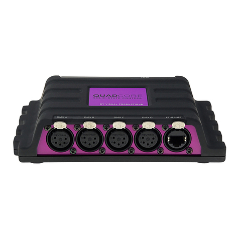
Figure 1.1: CueCore2
At the time of writing this manual the CueCore2’s firmware was at version
1.26.
1.1 Design Goals
After successfully developing and marketing the original CueCore1 , the team
at Visual Productions set out to design a new generation stand-alone lighting
controller. We took our experience in developing solid-state controllers and
combined it with the feedback received from CueCore1 users all over the world.
We added our lessons learnt from supporting year’s worth of projects and in-
stalls, all in order to design the best lighting controller for (semi-)permanent
installations. During the design process we focused on a set of priorities that
we valued the most:
6

1.1.1 Solid-State
The solid-state aspect was perhaps the most important trait that made the
CueCore1 a default choice for many system designers. The CueCore2 continues
this design without any moving part, without forced cooling, and its data safely
stored in flash memory. The resulted reliability outperforms any PC based
lighting system.
1.1.2 Multi-zone Replay Unit
One of the principle functions of the CueCore2 is to playback DMX shows. We
took a lot of consideration into making this feature as powerful as possible with
the given hardware platform. The playback mechanism we developed can control
six different zones. Each zone will be controlled by a completely independent
playback. This playback features many options that provides the freedom to
the users to employ very smart programming. These options include intensity,
rate, precedence, release-time, repeating, fading and inter-cue conditions.
1.1.3 Networking
Our world is one big connected network and the CueCore2 will blend in nicely.
This Ethernet-based device is setup via DHCP or static address, hosts a modern
web-interface for programming and is of course also powered by PoE.
1.1.4 Protocol Conversion
One of the strongest Unique Selling Points of the products designed at Vi-
sual Productions is the number of communication protocols supported. The
CueCore2 further raises this bar. It contains protocols familiar to the CueCore1
(DMX, Art-Net, UDP, OSC) and introduces a fresh set of new protocols: sACN,
KiNet, TCP and NTP. This vast collection of protocols can be used for record-
ing, sending, triggering and converting.
1.1.5 Scalability
One CueCore2 can do a lot, multiple CueCore2 units can do even more. Through
using CueluxPro it is possible to control up to 32 universes by connecting mul-
tiple CueCore2 units. For stand-alone scenarios we even developed a brand new
Master/Slave protocol that, once set up with just a few mouse clicks, allows 25
CueCore2 to work together and keep 50universes synchronised at 40 frames per
second.
We hope that you enjoy integrating the CueCore2 into your lighting designs.
The CueCore2 engineering team.
1.2 Features
The feature set of the CueCore2 includes:
7

•2 x DMX-512 optically isolated port (bi-directional)
•4x GPI
•MIDI, MSC & MMC
•SMPTE, MTC & Art-Net timecode
•Art-Net, sACN & KiNet
•TCP, UDP & OSC
•Master-slave protocol for synchronising multiple CueCore2 units
•Scheduling with Real-Time clock1, weekdays and sunrise/sunset
•NTP time synchronisation
•Desktop or DIN Rail mounted
•Kensington lock
•Locked power cable protection
•PoE (Power Over Ethernet) Class I
•Bundled with CueluxPro, vManager and Kiosc software
1.3 Comparison
The following table visualises the difference between the QuadCore, CueCore2
and CueCore1 . This overview might prove to be helpful to CueCore1 users
considering choosing the model for their new designs.
1Please note that there is no battery fitted inside the CueCore2. The Real-Time clock has
a backup charge through means of a super-capacitor.
8

QuadCore CueCore2 CueCore1
CPU Speed 180MHz 180MHz 120MHz
Flash memory 32MB 32MB 8MB
DMX Outputs 4 2 2
DMX Inputs switchable outputs switchable outputs 1
MIDI - input+output in+thru+out
GPI - 4x digital/analog 4x digital
SMPTE - input input
MTC - input+output input
Art-Net input+output input+output input+output
sACN input+output input+output -
KiNet output output -
TCP input input -
UDP input+output input+output input+output
OSC input+output input+output input+output
POE class I class I class I
DHCP yes yes -
NTP yes yes -
Real-time Clock yes yes yes
CueluxPro Licence 4 universes 2 universes 2 universes
1.4 What’s in the box?
The CueCore2 packaging contains the following items (see figure 1.2):
•CueCore2
•6-pin terminal
•Power supply
•4x international plug
•Info card
1.5 Saving data to memory
This manual will describe how to configure the CueCore2 and program tracks,
playbacks, action, etc. The unit’s web-interface is used for editing these kinds
of elements. When changes are made, these changes are directly stored in the
9

Figure 1.2: CueCore2 box contents
RAM memory of the CueCore2 and the programming will directly influence the
behaviour of the unit. RAM memory is, however, volatile and its content will be
lost through a power cycle. For this reason the CueCore2 will copy any changes
in the RAM memory to its onboard flash memory. Flash memory retains its
data even when not powered. The CueCore2 will load all its data back from the
flash memory upon startup.
This memory copy process is conducted automatically by the CueCore2 and
should not be of any concern of the user. One point of consideration is, how-
ever, that after making a change the unit should be given time to perform the
copy to flash. As a rule of thumb, do not disconnect the power from the device
within 30 seconds from making a programming change.
1.6 Document organisation
This manual discusses setting up and programming the unit. Chapter 2 provides
background information on the communication protocols used the CueCore2.
Chapters 4 and 5 cover how to set up the unit and configure the network con-
nection.
Chapter 7 and 8 cover recording, storing and playback of lighting content.
Programming the automation, triggering and converting functionality is
done in the 9 chapter.
When in a hurry, you could skip all chapters and directly follow the quickstart
tutorials in chapter 3.
1.7 Further Help
If, after reading this manual, you have further questions then please consult
the online forum at http://forum.visualproductions.nl for more technical
support.
10

Chapter 2
Protocols
The CueCore2 is fitted with several communication ports and supports various
protocols. This chapter describes these protocols and to which extent they are
implemented in the CueCore2
2.1 DMX-512
DMX-512 is the standard communication protocol for stage lighting. Its official
name is E1.11-2008 USITT DMX512-A. Nowadays the reach of the DMX proto-
col has extended beyond entertainment lighting and is also used for architectural
lighting.
Originally one DMX network contained 512 channels which is called a ’uni-
verse’. With the growing size and complexity of lighting systems it is now very
common for a system to compose of multiple universes, each conveying 512
channels.
It is advised to use a shielded twisted pair cable for DMX cabling. The cable
should be terminated with an 120 Ohm resistor.
DMX-512 is a very successful protocol with, however, a few limitations. The
maximum number of attached devices is limited to 32 and they all have to be
connected in bus-topology having one cable running via each device. Further-
more, a DMX-512 cable should not be longer than 300 meters.
Figure 2.1: Visual Productions’ RdmSplitter
11

The DIN Rail RdmSplitter from Visual Productions (See figure 2.1) helps tackle
those inconvenient limitations. The Splitter takes a DMX signal and sends it
out again on its 6 DMX output ports for scaling group topology. Each output
port is capable of driving 32 more devices. The Splitter can also function as a
signal booster as each port supports another 300 meter long connection.
The CueCore2 has two ports and is therefor able control 1,048 channels.
Each port can also be configured to become a DMX input allowing external
DMX data to be recorded or to use an external DMX source to trigger events
within the CueCore2.
2.2 Art-Net
The Art-Net protocol primarily transfers DMX-512 data over Ethernet. The
high bandwidth of an Ethernet connection allows Art-Net to transfer up to 256
universes.
The data sent out for Art-Net does put a certain load on the network, there-
fore it is recommended to disable Art-Net when not in use.
Additional to transmitting DMX-512 data, Art-Net can also be used for
transferring timecode information for equipment synchronisation.
Each CueCore2 supports sending and receiving of 2 Art-Net universes as
well as receiving Art-Net timecode.
2.3 sACN
The streaming Architecture of Control Networks (sACN) protocol uses a method
of transporting DMX-512 information over TCP/IP networks. The protocol is
specified in the ANSI E1.31-2009 standard.
The sACN protocol supports multi-cast in order to take efficient use of the
network’s bandwidth.
The CueCore2 supports sending and receiving of 2 sACN universes.
2.4 KiNet
KiNet is a proprietary protocol of Philips Color Kinetics to control their LED
fixtures and power supplies. It is a lightweight Ethernet-based protocol that
carries DMX-style data. Within the CueCore2 it can only be used to output
data.
2.5 TCP
The Transmission Control Protocol (TCP) is a core protocol of the Internet
Protocol Suite. It is used for its reliable, ordered and error checked delivery
of a stream of bytes between applications and hosts over IP networks. It is
considered ’reliable’ because the protocol itself checks to see if everything that
was transmitted was delivered at the receiving end. TCP allows for the retrans-
mission of lost packets, thereby making sure that all data transmitted is received.
12

The CueCore2 supports reception of TCP message.
2.6 UDP
User Datagram Protocol (UDP) is a simple protocol for sending messages across
the network. It is supported by various media devices like video projectors and
Show Controllers. It does not incorporate error checking, therefor it is faster
than TCP but less reliable.
There are two ways how to have the CueCore2 respond to incoming UDP
messages. The API (see page 101) makes typical CueCore2 functions available
through UDP. Furthermore, custom messages can be programmed in the Show
Control page (see page 53). This is also the place where to program outgoing
UDP messages.
2.7 OSC
Open Sound Control (OSC) is a protocol for communicating between software
and various multi-media type devices. OSC uses the network to send and receive
messages, it can contain MIDI and custom information.
There are apps available for creating custom-made user interfaces on iOS
(iPod, iPhone, iPad) and Android. These tools allow to program fool-proof
user-interfaces for controlling the device. E.g. Kiosc from Visual Productions.
There are two ways how to have the CueCore2 respond to incoming OSC
messages. Firstly, the API (see page 99) makes typical CueCore2 functions
available through OSC. Secondly, custom messages can be programmed in the
Show Control page (see page 53).
2.8 GPI
The CueCore2 features four General Purpose Inputs (GPI) ports that can be
connected to external equipment, switches and sensors. State changes on these
GPI ports can be used to trigger programmed events inside the CueCore2.
Figure 2.2: GPI Pinout
13

Each GPI port can be switched between ’digital’ and ’analog’. In the digital
mode the signal is held up by an internal pull-up resistor and results in a logic
’0’. The external equipment is intended to short the port’s pin to the provided
ground pin. This short will create a logic ’1’. All four ports share one common
ground pin.
When set to analog the external equipment is supposed to supply a voltage
between 0V and 10V to the port’s pin. For convenience, a 10V supply is available
on one of the pins of the GPI connector. Please refer to figure 2.2 for the pinout
of the GPI connector. Be careful not to supply more than 10V to the GPI port
as that might cause permanent damage.
Figure 2.3 shows examples of how to wire a contact-closure to a GPI port
set to digital. And it shows an example of potentiometer connected to a GPI
port set to analog.
(a) Contact-closure (b) Potentiometer
Figure 2.3: GPI Wiring examples
Please refer to page 72 for more information on configuring the GPI ports.
Programming events based on GPI activity is done in the Show Control page,
which is discussed on page 53.
2.9 MIDI
The MIDI protocol is intended for inter-connecting musical devices such as syn-
thesisers and sequencers. Furthermore, this protocol is also very suitable to
send triggers from one device to another and is often used to synchronise audio,
video and lighting equipment. There is also a large collection of MIDI con-
trol surfaces available; user-interface consoles with knobs, (motorised-)faders,
rotary-encoders, etc.
The CueCore2 is fitted with a MIDI input and MIDI output port. It supports
receiving and sending MIDI messages like NoteOn, NoteOff, ControlChange and
ProgramChange.
2.9.1 MTC
MIDI Timecode (MTC) is the timecode signal which is embedded into MIDI.
The CueCore2 supports receiving and transmitting MTC. It is not recommended
to combine the use of MTC with ordinary MIDI as MTC consumes the band-
width of the MIDI connection.
14

2.9.2 MMC
MIDI Machine Control (MMC) is part of the MIDI protocol. It defines special
messages for controlling audio equipment such as multi-track recorders. The
CueCore2 supports the sending of MMC commands; please refer to page 94.
2.9.3 MSC
MIDI Show Control (MSC) is an extension of the MIDI protocol. It comprises
of commands for synchronising show equipment like lighting, video and audio
devices. The CueCore2 supports receiving MSC commands. This support is
hard coded and does not require any Show Control programming. Please refer
to appendix D.4.
2.10 SMPTE
SMPTE is timecode signal which can be used to synchronise audio, video, light-
ing and other show equipment. The CueCore2 supports receiving SMPTE that
is transferred as an audio signal, also know as LTC timecode.
The CueCore2 only supports receiving timecode. If a timecode generator is
required then the Visual Productions’ TimeCore is recommended as shown in
figure 2.4.
Figure 2.4: TimeCore
2.11 NTP
Network Time Protocol (NTP) is a networking protocol for clock synchronisa-
tion between computer systems over networks.
The real-time clock (RTC) in the CueCore2 can be synchronised to an ex-
ternal time server using the NTP protocol.
2.12 DHCP
The Dynamic Host Configuration Protocol (DHCP) is a standardised network
protocol used on Internet Protocol (IP) networks for dynamically distributing
network configuration parameters, such as IP addresses.
15

The CueCore2 is a DHCP client.
16

Chapter 3
Quickstart
This chapter provides step by step tutorials on how to program your CueCore2
for some typical tasks:
•Playback lighting scenes based on the scheduler
•Choose between different lighting scenes via incoming UDP messages
•Record a show from an external DMX console
3.1 Playback based on scheduler
This tutorial shows how to create a lighting scene and have it activated at a
certain time of the day. The scene will be de-activated at another time. Follow
the steps below:
1. Connect to the network
Connect the CueCore2 with an Ethernet cable to the router. It
is required that the network is managed by a router that fea-
tures a DHCP server. If the network router is not DHCP capa-
ble then read the network chapter on page 30 for alternative setups.
17

2. Install the vManager
To access the web-interface of the CueCore2, the vManager tool is
required. This tool can be downloaded from the Visual Productions
website. Once the installation is complete, run the vManager to discover
the IP address of the CueCore2.
3. Open the web-interface
Choose the CueCore2 from the device list and click on the Browse button
to open the web-interface.
4. Create the scene
Use the browser to go to the CueCore2’s ’Track’ page. Select a track
from the table and press the ’Open Console’ button. Create a scene by
using the command-line syntax. E.g. 1<thru>3 @ <full>
18

5. Create a cue
Go to the Playback page and select Playback 1. Press the Add button to
create a new cue. Once the Cue is added it will automatically refer to
Track 1.
6. Start playback
Press Go+ on the transport area to start the Playback. The playback
now indicated the green ’play’ icon.
19

3.2 Choose scenes via UDP
This example will create two lighting scenes. They will be put into a single
playback. This means only one scene will be active at a time. Furthermore, a
cross-fade will be defined between the scenes and the scenes will be triggered
by receiving simple UDP network messages. Please take the following steps:
1. Connect to the network
Connect the CueCore2 with an Ethernet cable to the router. It
is required that the network is managed by a router that fea-
tures a DHCP server. If the network router is not DHCP capa-
ble then read the network chapter on page 30 for alternative setups.
2. Create the first scene
Use the browser to go to the CueCore2’s ’Track’ page. Select a track from
the table and press the ’Open Console’ button. Create a scene by using
the command-line syntax. E.g. 1 @ <full>or 2+3 @ 50 <enter>
20
Table of contents
Other Visual Productions Controllers manuals
Popular Controllers manuals by other brands
Galletti
Galletti TED2T Installation and use manual
Mitsubishi
Mitsubishi MELSEC-L Series user manual

rauland
rauland 2524 ChronoCom Operation manual
Bosch
Bosch Worcester Digital Twin Channel Programmer Installation & operating instructions
Danfoss
Danfoss VLT AQUA Drive FC 200 Programming guide
Elko
Elko iNels LBC3-02M instruction manual

